


GE Fanuc Automation
Computer Numerical Control Products
Series 15 / 150 – Model B
Connection Manual (Hardware)
GFZ-62073E/04 |
November 1998 |

GFL-001
Warnings, Cautions, and Notes as Used in this Publication
Warning
Warning notices are used in this publication to emphasize that hazardous voltages, currents, temperatures, or other conditions that could cause personal injury exist in this equipment or may be associated with its use.
In situations where inattention could cause either personal injury or damage to equipment, a Warning notice is used.
Caution
Caution notices are used where equipment might be damaged if care is not taken.
Note
Notes merely call attention to information that is especially significant to understanding and operating the equipment.
This document is based on information available at the time of its publication. While efforts have been made to be accurate, the information contained herein does not purport to cover all details or variations in hardware or software, nor to provide for every possible contingency in connection with installation, operation, or maintenance. Features may be described herein which are not present in all hardware and software systems. GE Fanuc Automation assumes no obligation of notice to holders of this document with respect to changes subsequently made.
GE Fanuc Automation makes no representation or warranty, expressed, implied, or statutory with respect to, and assumes no responsibility for the accuracy, completeness, sufficiency, or usefulness of the information contained herein. No warranties of merchantability or fitness for purpose shall apply.
©Copyright 1998 GE Fanuc Automation North America, Inc.
All Rights Reserved.

B±62073E/04 |
DEFINITION OF WARNING, CAUTION, AND NOTE |
|
|
DEFINITION OF WARNING, CAUTION, AND NOTE
This manual includes safety precautions for protecting the user and preventing damage to the machine. Precautions are classified into Warning and Caution according to their bearing on safety. Also, supplementary information is described as a Note. Read the Warning, Caution, and Note thoroughly before attempting to use the machine.
WARNING
Applied when there is a danger of the user being injured or when there is a danger of both the user being injured and the equipment being damaged if the approved procedure is not observed.
CAUTION
Applied when there is a danger of the equipment being damaged, if the approved procedure is not observed.
NOTE
The Note is used to indicate supplementary information other than Warning and Caution.
`Read this manual carefully, and store it in a safe place.
s±1
B±62073E/04 |
Table of Contents |
DEFINITION OF WARNING, CAUTION, AND NOTE . . . . . . . . . . . . . . . . . . . . . . . . . . . . . s±1 1. GENERAL . . . . . . . . . . . . . . . . . . . . . . . . . . . . . . . . . . . . . . . . . . . . . . . . . . . . . . . . . . . . . . . . . . . 1 2. CONFIGURATION . . . . . . . . . . . . . . . . . . . . . . . . . . . . . . . . . . . . . . . . . . . . . . . . . . . . . . . . . . . . 4 3. INSTALLATION . . . . . . . . . . . . . . . . . . . . . . . . . . . . . . . . . . . . . . . . . . . . . . . . . . . . . . . . . . . . . . 6
3.1 |
ENVIRONMENTAL REQUIREMENTS . . . . . . . . . . . . . . . . . . . . . . . . . . . . . . . . . . . . . . . . . . . . . . |
. 7 |
|
|
3.1.1 |
Cabinet Exterior Environmental Requirements . . . . . . . . . . . . . . . . . . . . . . . . . . . . . . . . . . . . . |
. 7 |
|
3.1.2 |
Installation Conditions of the CNC Inside Cabinet and Servo Unit . . . . . . . . . . . . . . . . . . . . . . |
. 8 |
3.2 |
POWER CAPACITY . . . . . . . . . . . . . . . . . . . . . . . . . . . . . . . . . . . . . . . . . . . . . . . . . . . . . . . . . . . . . . |
. 9 |
|
3.3 |
CABINET DESIGN AND INSTALLATION CONDITIONS OF |
|
|
|
THE MACHINE TOOL MAGNETIC . . . . . . . . . . . . . . . . . . . . . . . . . . . . . . . . . . . . . . . . . . . . . . . . . |
10 |
|
3.4 |
THERMAL DESIGN OF THE CABINET . . . . . . . . . . . . . . . . . . . . . . . . . . . . . . . . . . . . . . . . . . . . . |
13 |
|
|
3.4.1 |
Temperature Rise within the Cabinet . . . . . . . . . . . . . . . . . . . . . . . . . . . . . . . . . . . . . . . . . . . . . |
13 |
|
3.4.2 |
Cooling by Heat Exchanger . . . . . . . . . . . . . . . . . . . . . . . . . . . . . . . . . . . . . . . . . . . . . . . . . . . . |
13 |
|
3.4.3 |
Heat Loss of Each Unit . . . . . . . . . . . . . . . . . . . . . . . . . . . . . . . . . . . . . . . . . . . . . . . . . . . . . . . . |
14 |
3.5 |
INSTALLING THE HEAT EXCHANGER . . . . . . . . . . . . . . . . . . . . . . . . . . . . . . . . . . . . . . . . . . . . . |
16 |
|
|
3.5.1 |
Cooling Fin A/B/C . . . . . . . . . . . . . . . . . . . . . . . . . . . . . . . . . . . . . . . . . . . . . . . . . . . . . . . . . . . |
16 |
|
3.5.2 |
Heat Exchanger for CRT/MDI Unit . . . . . . . . . . . . . . . . . . . . . . . . . . . . . . . . . . . . . . . . . . . . . . |
21 |
|
3.5.3 |
The Heat Pipe Type Heat Exchanger . . . . . . . . . . . . . . . . . . . . . . . . . . . . . . . . . . . . . . . . . . . . . |
24 |
|
3.5.3.1 |
Installation . . . . . . . . . . . . . . . . . . . . . . . . . . . . . . . . . . . . . . . . . . . . . . . . . . . . . . . . . . . . . . . . . . |
24 |
|
3.5.3.2 |
Maintenance . . . . . . . . . . . . . . . . . . . . . . . . . . . . . . . . . . . . . . . . . . . . . . . . . . . . . . . . . . . . . . . . |
27 |
3.6 |
ACTION AGAINST NOISE . . . . . . . . . . . . . . . . . . . . . . . . . . . . . . . . . . . . . . . . . . . . . . . . . . . . . . . . |
30 |
|
|
3.6.1 |
Separating Signal Lines . . . . . . . . . . . . . . . . . . . . . . . . . . . . . . . . . . . . . . . . . . . . . . . . . . . . . . . |
30 |
|
3.6.2 |
Ground . . . . . . . . . . . . . . . . . . . . . . . . . . . . . . . . . . . . . . . . . . . . . . . . . . . . . . . . . . . . . . . . . . . . . |
31 |
|
3.6.3 |
Grounding Each Unit . . . . . . . . . . . . . . . . . . . . . . . . . . . . . . . . . . . . . . . . . . . . . . . . . . . . . . . . . |
33 |
|
3.6.4 |
Noise Suppressor . . . . . . . . . . . . . . . . . . . . . . . . . . . . . . . . . . . . . . . . . . . . . . . . . . . . . . . . . . . . . |
36 |
|
3.6.5 |
Cable Clamp and Shield Processing . . . . . . . . . . . . . . . . . . . . . . . . . . . . . . . . . . . . . . . . . . . . . . |
37 |
3.7 |
CONTROL UNIT . . . . . . . . . . . . . . . . . . . . . . . . . . . . . . . . . . . . . . . . . . . . . . . . . . . . . . . . . . . . . . . . . |
40 |
|
|
3.7.1 |
Configuration and Installation of the Control Unit . . . . . . . . . . . . . . . . . . . . . . . . . . . . . . . . . . |
40 |
|
3.7.2 |
Battery for Memory Backup . . . . . . . . . . . . . . . . . . . . . . . . . . . . . . . . . . . . . . . . . . . . . . . . . . . . |
44 |
|
3.7.3 |
Replacing the Battery . . . . . . . . . . . . . . . . . . . . . . . . . . . . . . . . . . . . . . . . . . . . . . . . . . . . . . . . . |
45 |
3.8 |
CABLE LEAD±IN DIAGRAM . . . . . . . . . . . . . . . . . . . . . . . . . . . . . . . . . . . . . . . . . . . . . . . . . . . . . . |
47 |
|
|
3.8.1 |
Configuration of Control Unit Connectors . . . . . . . . . . . . . . . . . . . . . . . . . . . . . . . . . . . . . . . . . |
47 |
|
3.8.2 |
Cable Lead±in for Stand±alone Cabinet A . . . . . . . . . . . . . . . . . . . . . . . . . . . . . . . . . . . . . . . . . |
67 |
|
3.8.3 |
Cable Lead±in for Stand±alone Cabinet B . . . . . . . . . . . . . . . . . . . . . . . . . . . . . . . . . . . . . . . . . |
68 |
|
3.8.4 |
Cable Lead±in for Additional Cabinet A . . . . . . . . . . . . . . . . . . . . . . . . . . . . . . . . . . . . . . . . . . |
69 |
3.9 |
MAINTENANCE AREA . . . . . . . . . . . . . . . . . . . . . . . . . . . . . . . . . . . . . . . . . . . . . . . . . . . . . . . . . . . |
70 |
|
|
3.9.1 |
Maintenance Area for Self±standing A Type Cabinet . . . . . . . . . . . . . . . . . . . . . . . . . . . . . . . . |
70 |
|
3.9.2 |
Maintenance Area for Self±standing B Type Cabinet . . . . . . . . . . . . . . . . . . . . . . . . . . . . . . . . |
71 |
|
3.9.3 |
Maintenance Area for Additional Cabinet A . . . . . . . . . . . . . . . . . . . . . . . . . . . . . . . . . . . . . . . |
72 |
4. TOTAL CONNECTION . . . . . . . . . . . . . . . . . . . . . . . . . . . . . . . . . . . . . . . . . . . . . . . . . . . . . . |
73 |
||
4.1CONNECTION DIAGRAM FOR SERIES 15±TB/TTB/MB/TFB/TTFB/MFB,
SERIES 150±TB/MB/TTB (IN CASE OF SERIAL SPINDLE) . . . . . . . . . . . . . . . . . . . . . . . . . . . . . 74
4.1.1Connection Diagram for Series 15±TB/TTB/MB/TFB/TTFB/MFB, Series 150±TB/MB/TTB
(When LCD/MDI Unit with Built±in Graphic Functions is not Used) . . . . . . . . . . . . . . . . . . . 74
4.1.2 |
Connection Diagram for Series 15±TB/TTB/MB |
|
|
(When LCD/MDI Unit with Built±in Graphic Functions is Used) . . . . . . . . . . . . . . . . . . . . . . |
77 |
c±1
TABLE OF CONTENTS |
B±62073E/04 |
|
|
4.2CONNECTION DIAGRAM FOR SERIES 15±TB/TTB/MB/TFB/TTFB/MFB,
SERIES 150±TB/MB/TTB (IN CASE OF ANALOG SPINDLE) . . . . . . . . . . . . . . . . . . . . . . . . . . . 80
4.3CONNECTION DIAGRAM FOR SERIES 15±MB OR SERIES 150±MB
(IN CASE OF MULTIPLE AXIS) . . . . . . . . . . . . . . . . . . . . . . . . . . . . . . . . . . . . . . . . . . . . . . . . . . . . 83 4.3.1 Control Unit . . . . . . . . . . . . . . . . . . . . . . . . . . . . . . . . . . . . . . . . . . . . . . . . . . . . . . . . . . . . . . . . 84 4.3.2 Additional Cabinet (In Case of Serial Spindle Interface) . . . . . . . . . . . . . . . . . . . . . . . . . . . . . . 85 4.3.3 Additional Cabinet (In Case of Analog Spindle Interface) . . . . . . . . . . . . . . . . . . . . . . . . . . . . 86 4.3.4 Connection Between the Control Unit and Additional Locker . . . . . . . . . . . . . . . . . . . . . . . . . 88
4.4 CONNECTION DIAGRAM FOR SERIES 15±B (IN CASE OF MMC±II) . . . . . . . . . . . . . . . . . . . . 89 4.5 CONNECTION DIAGRAM FOR SERIES 15±B (IN CASE OF MMC±III) . . . . . . . . . . . . . . . . . . . 91 4.6 CONNECTION DIAGRAM FOR MMC±IV . . . . . . . . . . . . . . . . . . . . . . . . . . . . . . . . . . . . . . . . . . . 92
5. POWER SUPPLY UNIT AND INPUT UNIT CONNECTION . . . . . . . . . . . . . . . . . . . . . . . |
94 |
||
5.1 |
POWER SUPPLY UNIT PANEL LAYOUT . . . . . . . . . . . . . . . . . . . . . . . . . . . . . . . . . . . . . . . . . . . . |
95 |
|
5.2 |
CONNECTING THE POWER SUPPLY UNIT . . . . . . . . . . . . . . . . . . . . . . . . . . . . . . . . . . . . . . . . . |
97 |
|
|
5.2.1 When an Input Unit is not Used . . . . . . . . . . . . . . . . . . . . . . . . . . . . . . . . . . . . . . . . . . . . . . . . . |
97 |
|
|
5.2.2 When an Input Unit is Used . . . . . . . . . . . . . . . . . . . . . . . . . . . . . . . . . . . . . . . . . . . . . . . . . . . |
100 |
|
|
5.2.3 When AC Output Terminals for Which Power On/Off is Controlled are Insufficient . . . . . . . |
103 |
|
|
5.2.4 |
Power ON Sequence . . . . . . . . . . . . . . . . . . . . . . . . . . . . . . . . . . . . . . . . . . . . . . . . . . . . . . . . . |
104 |
|
5.2.5 |
Power OFF Sequence . . . . . . . . . . . . . . . . . . . . . . . . . . . . . . . . . . . . . . . . . . . . . . . . . . . . . . . . |
104 |
5.3 |
CONNECTION OF INPUT UNIT FOR STANDALONE CABINET A . . . . . . . . . . . . . . . . . . . . . |
105 |
|
|
5.3.1 |
Input Unit Layout . . . . . . . . . . . . . . . . . . . . . . . . . . . . . . . . . . . . . . . . . . . . . . . . . . . . . . . . . . . |
105 |
|
5.3.2 Connection to Input Units (A14B±0076±B004, ±B005, and ±B008) . . . . . . . . . . . . . . . . . . . . |
105 |
|
|
5.3.3 Connection to the Control Unit . . . . . . . . . . . . . . . . . . . . . . . . . . . . . . . . . . . . . . . . . . . . . . . . . |
109 |
|
5.4 |
CONNECTION OF INPUT UNIT FOR STANDALONE CABINET B . . . . . . . . . . . . . . . . . . . . . |
110 |
|
|
5.4.1 |
Input Unit Layout . . . . . . . . . . . . . . . . . . . . . . . . . . . . . . . . . . . . . . . . . . . . . . . . . . . . . . . . . . . |
110 |
|
5.4.2 Connection to Input Unit (A14B±0076±B411) . . . . . . . . . . . . . . . . . . . . . . . . . . . . . . . . . . . . . |
111 |
|
|
5.4.3 Connection to Control Unit . . . . . . . . . . . . . . . . . . . . . . . . . . . . . . . . . . . . . . . . . . . . . . . . . . . . |
114 |
|
5.5 |
CONNECTION OF INPUT UNIT FOR ADDITIONAL CABINET A . . . . . . . . . . . . . . . . . . . . . . |
115 |
|
|
5.5.1 |
Input Unit Layout . . . . . . . . . . . . . . . . . . . . . . . . . . . . . . . . . . . . . . . . . . . . . . . . . . . . . . . . . . . |
115 |
|
5.5.2 |
Cable Connection |
|
|
|
[Connection to the Input Unit (A02B±0075±J141, ±J142, ±J144, and ±J145)] . . . . . . . . . . . . |
116 |
6. CONNECTION OF I/O UNITS TO MACHINE INTERFACE . . . . . . . . . . . . . . . . . . . . . . 120
6.1 OUTLINE . . . . . . . . . . . . . . . . . . . . . . . . . . . . . . . . . . . . . . . . . . . . . . . . . . . . . . . . . . . . . . . . . . . . . . 121 6.2 CONNECTION OF THE FANUC I/O LINK . . . . . . . . . . . . . . . . . . . . . . . . . . . . . . . . . . . . . . . . . . 123 6.2.1 Connection of FANUC I/O Link by Electric Cable . . . . . . . . . . . . . . . . . . . . . . . . . . . . . . . . . 125 6.2.2 Connection of FANUC I/O Link by Optical Fiber Cable . . . . . . . . . . . . . . . . . . . . . . . . . . . . . 126 6.3 CONNECTION OF THE FANUC I/O UNIT±MODEL A . . . . . . . . . . . . . . . . . . . . . . . . . . . . . . . . 131 6.3.1 Structure of FANUC I/O Unit±MODEL A . . . . . . . . . . . . . . . . . . . . . . . . . . . . . . . . . . . . . . . . 131 6.3.2 Outer Dimensions . . . . . . . . . . . . . . . . . . . . . . . . . . . . . . . . . . . . . . . . . . . . . . . . . . . . . . . . . . . 132 6.3.3 Mounting and Dismounting Modules . . . . . . . . . . . . . . . . . . . . . . . . . . . . . . . . . . . . . . . . . . . . 132 6.3.4 Connection Diagram . . . . . . . . . . . . . . . . . . . . . . . . . . . . . . . . . . . . . . . . . . . . . . . . . . . . . . . . . 134 6.3.5 Connecting Input Power Source . . . . . . . . . . . . . . . . . . . . . . . . . . . . . . . . . . . . . . . . . . . . . . . . 135 6.3.6 Grounding . . . . . . . . . . . . . . . . . . . . . . . . . . . . . . . . . . . . . . . . . . . . . . . . . . . . . . . . . . . . . . . . . 136 6.3.7 Connecting Signal Cables . . . . . . . . . . . . . . . . . . . . . . . . . . . . . . . . . . . . . . . . . . . . . . . . . . . . . 138 6.3.8 Connecting with I/O Modules . . . . . . . . . . . . . . . . . . . . . . . . . . . . . . . . . . . . . . . . . . . . . . . . . . 141
c±2
B±62073E/04 |
TABLE OF CONTENTS |
|
|
6.3.9 Digital Input/Output Module . . . . . . . . . . . . . . . . . . . . . . . . . . . . . . . . . . . . . . . . . . . . . . . . . . 143 6.3.10 Correspondence between I/O Signals and Addresses in a Module . . . . . . . . . . . . . . . . . . . . . 145 6.3.11 Number of I/O Points for I/O Unit±MODEL A . . . . . . . . . . . . . . . . . . . . . . . . . . . . . . . . . . . . 145 6.4 CONNECTING THE CONNECTION UNIT . . . . . . . . . . . . . . . . . . . . . . . . . . . . . . . . . . . . . . . . . . 147 6.4.1 Connecting Connection Unit 1 and Connection Unit 2 . . . . . . . . . . . . . . . . . . . . . . . . . . . . . . 149 6.4.2 Input Signal Regulations for the Connection Unit . . . . . . . . . . . . . . . . . . . . . . . . . . . . . . . . . . 151 6.4.3 Output Signal Regulations for the Connection Unit . . . . . . . . . . . . . . . . . . . . . . . . . . . . . . . . . 153 6.4.4 Connector Pin Assignment for the Connection Unit . . . . . . . . . . . . . . . . . . . . . . . . . . . . . . . . 154 6.4.5 Details of the Connection between the Connection Unit and the Machine . . . . . . . . . . . . . . . 156 6.4.6 External View of the Connection Unit . . . . . . . . . . . . . . . . . . . . . . . . . . . . . . . . . . . . . . . . . . . 174 6.5 CONNECTION OF OPERATOR'S PANEL CONNECTION UNIT . . . . . . . . . . . . . . . . . . . . . . . . 175 6.5.1 Input Signal Regulations for the Operator's Panel Connection Unit . . . . . . . . . . . . . . . . . . . . 176 6.5.2 Output Signal Regulations for the Operator's Panel Connection Unit . . . . . . . . . . . . . . . . . . 177 6.5.3 Connector Layout for Operator's Panel Connection Unit . . . . . . . . . . . . . . . . . . . . . . . . . . . . 179
6.5.4Details of the Connection between the Operator's Panel Connection Unit and the Machine . 181
6.5.5 External View of Operator's Panel Connection Unit . . . . . . . . . . . . . . . . . . . . . . . . . . . . . . . . 188 6.6 CONNECTION OF SOURCE OUTPUT OPERATOR'S PANEL CONNECTION UNIT . . . . . . . 189 6.6.1 Source Output Operator's Panel Connection Unit Input Signal Standard . . . . . . . . . . . . . . . . 190 6.6.2 Output Signal Standard for Source Output Operator's Panel Connection Unit . . . . . . . . . . . . 192 6.6.3 ALARM LEDs on Source Output Operator's Panel Connection Unit . . . . . . . . . . . . . . . . . . . 195
6.6.4Connector Pin Assignment Addresses of Source Output
Operator's Panel Connection Unit . . . . . . . . . . . . . . . . . . . . . . . . . . . . . . . . . . . . . . . . . . . . . . 197
6.6.5Details of Machine Side Connections of Source Output Operator's Panel Connection Unit . 199
6.6.6 External Dimensions of Source Output Operator's Panel Connection Unit . . . . . . . . . . . . . . 206 6.7 ADDRESS±FIXED SIGNALS . . . . . . . . . . . . . . . . . . . . . . . . . . . . . . . . . . . . . . . . . . . . . . . . . . . . . 207
7. CONNECTION TO CNC PERIPHERALS . . . . . . . . . . . . . . . . . . . . . . . . . . . . . . . . . . . . . 208
7.1 CRT/MDI UNIT INTERFACE . . . . . . . . . . . . . . . . . . . . . . . . . . . . . . . . . . . . . . . . . . . . . . . . . . . . . 209 7.1.1 Outline . . . . . . . . . . . . . . . . . . . . . . . . . . . . . . . . . . . . . . . . . . . . . . . . . . . . . . . . . . . . . . . . . . . . 209 7.1.2 9″ CRT or 9″ PDP Display Interface (CE Marking Non±compliant) . . . . . . . . . . . . . . . . . . . . 214 7.1.3 9″ CRT or PDP Display Interface (CE Marking Compliant) . . . . . . . . . . . . . . . . . . . . . . . . . . 216
7.1.414″ Analog CRT, 10.4″ LCD, 9.5″ LCD Display Interface
(CE Marking Compliant when MMC±IV is not Used) . . . . . . . . . . . . . . . . . . . . . . . . . . . . . . 218
7.1.514″ Analog CRT, 10.4″ LCD, 9.5″ LCD Display Interface
(CE Marking Compliant when MMC±IV is Used) . . . . . . . . . . . . . . . . . . . . . . . . . . . . . . . . . . 220 7.1.6 10.4″ LCD Display Interface (CE Marking Compliant with Built±in Graphic Function) . . . . 222 7.1.7 Adjusting the Flat Display . . . . . . . . . . . . . . . . . . . . . . . . . . . . . . . . . . . . . . . . . . . . . . . . . . . . 224 7.1.8 Interface between MMC±IV Board and Option 1 Board (Video Signal) . . . . . . . . . . . . . . . . . 225 7.1.9 Keyboard Interface . . . . . . . . . . . . . . . . . . . . . . . . . . . . . . . . . . . . . . . . . . . . . . . . . . . . . . . . . . 226 7.1.10 Small 9″ Keyboard Interface . . . . . . . . . . . . . . . . . . . . . . . . . . . . . . . . . . . . . . . . . . . . . . . . . . . 227 7.1.11 Interface between MMC±III Board and Option 1 Board (Video Signal) . . . . . . . . . . . . . . . . . 228
7.2 I/O DEVICE INTERFACE . . . . . . . . . . . . . . . . . . . . . . . . . . . . . . . . . . . . . . . . . . . . . . . . . . . . . . . . 229 7.2.1 RS±232±C Serial Port . . . . . . . . . . . . . . . . . . . . . . . . . . . . . . . . . . . . . . . . . . . . . . . . . . . . . . . . 229 7.2.2 PPR Connection . . . . . . . . . . . . . . . . . . . . . . . . . . . . . . . . . . . . . . . . . . . . . . . . . . . . . . . . . . . . 230 7.2.3 Portable Tape Reader Connection . . . . . . . . . . . . . . . . . . . . . . . . . . . . . . . . . . . . . . . . . . . . . . . 231 7.2.4 FANUC Cassette Connection . . . . . . . . . . . . . . . . . . . . . . . . . . . . . . . . . . . . . . . . . . . . . . . . . . 232 7.2.5 Connection with the FANUC Handy File . . . . . . . . . . . . . . . . . . . . . . . . . . . . . . . . . . . . . . . . . 233 7.2.6 Connection of Tape Reader Without Reels . . . . . . . . . . . . . . . . . . . . . . . . . . . . . . . . . . . . . . . . 234 7.2.7 Connection of Tape Reader with Reels . . . . . . . . . . . . . . . . . . . . . . . . . . . . . . . . . . . . . . . . . . 235 7.2.8 RS±422 Serial Port . . . . . . . . . . . . . . . . . . . . . . . . . . . . . . . . . . . . . . . . . . . . . . . . . . . . . . . . . . 236
c±3
TABLE OF CONTENTS |
B±62073E/04 |
|
|
7.3 MANUAL PULSE GENERATOR INTERFACE . . . . . . . . . . . . . . . . . . . . . . . . . . . . . . . . . . . . . . . 238 7.4 REMOTE BUFFER INTERFACE (RS±232±C) . . . . . . . . . . . . . . . . . . . . . . . . . . . . . . . . . . . . . . . . 240 7.5 REMOTE BUFFER INTERFACE (RS±422) . . . . . . . . . . . . . . . . . . . . . . . . . . . . . . . . . . . . . . . . . . 242 7.6 HIGH±SPEED DI SIGNAL INTERFACE . . . . . . . . . . . . . . . . . . . . . . . . . . . . . . . . . . . . . . . . . . . . 244 7.7 CONNECTION OF REFERENCE POSITION APPROACH SIGNAL . . . . . . . . . . . . . . . . . . . . . . 247 7.8 DNC INTERFACE . . . . . . . . . . . . . . . . . . . . . . . . . . . . . . . . . . . . . . . . . . . . . . . . . . . . . . . . . . . . . . . 248
7.8.1 DNC1 Interface . . . . . . . . . . . . . . . . . . . . . . . . . . . . . . . . . . . . . . . . . . . . . . . . . . . . . . . . . . . . . 248
7.8.2 DNC2 Interface (RS±232±C) . . . . . . . . . . . . . . . . . . . . . . . . . . . . . . . . . . . . . . . . . . . . . . . . . . 250
7.8.3 DNC2 Interface (RS422) . . . . . . . . . . . . . . . . . . . . . . . . . . . . . . . . . . . . . . . . . . . . . . . . . . . . . . 251
7.9 SPINDLE INTERFACE . . . . . . . . . . . . . . . . . . . . . . . . . . . . . . . . . . . . . . . . . . . . . . . . . . . . . . . . . . . 252
7.9.1 Serial Spindle Interface (S Series Spindle) . . . . . . . . . . . . . . . . . . . . . . . . . . . . . . . . . . . . . . . . 254 7.9.2 Serial Spindle Interface (α Series) . . . . . . . . . . . . . . . . . . . . . . . . . . . . . . . . . . . . . . . . . . . . . . 255
7.9.3 Analog Spindle Interface . . . . . . . . . . . . . . . . . . . . . . . . . . . . . . . . . . . . . . . . . . . . . . . . . . . . . 256 7.9.4 Pulse Coder Interface . . . . . . . . . . . . . . . . . . . . . . . . . . . . . . . . . . . . . . . . . . . . . . . . . . . . . . . . 257 7.10 SERVO INTERFACE . . . . . . . . . . . . . . . . . . . . . . . . . . . . . . . . . . . . . . . . . . . . . . . . . . . . . . . . . . . . 259 7.10.1 Outline . . . . . . . . . . . . . . . . . . . . . . . . . . . . . . . . . . . . . . . . . . . . . . . . . . . . . . . . . . . . . . . . . . . . 259 7.10.2 Servo Amp Interface . . . . . . . . . . . . . . . . . . . . . . . . . . . . . . . . . . . . . . . . . . . . . . . . . . . . . . . . . 260 7.10.3 Serial Pulse Coder Interface . . . . . . . . . . . . . . . . . . . . . . . . . . . . . . . . . . . . . . . . . . . . . . . . . . . 263 7.10.4 Linear Scale Interface (A/B/Z Signal Interface) . . . . . . . . . . . . . . . . . . . . . . . . . . . . . . . . . . . 269 7.10.5 Linear Scale Interface (Serial Interface) . . . . . . . . . . . . . . . . . . . . . . . . . . . . . . . . . . . . . . . . . . 271 7.10.6 APC Battery Interface . . . . . . . . . . . . . . . . . . . . . . . . . . . . . . . . . . . . . . . . . . . . . . . . . . . . . . . . 272 7.10.7 Hybrid±control Connections . . . . . . . . . . . . . . . . . . . . . . . . . . . . . . . . . . . . . . . . . . . . . . . . . . . 273 7.11 GENERAL±PURPOSE ANALOG VOLTAGE INPUT INTERFACE . . . . . . . . . . . . . . . . . . . . . . . 274 7.12 CONNECTION BETWEEN THE SERIES 15±B (MMC±II) AND PERIPHERAL UNITS . . . . . . 275
7.13CONNECTION WITH AN EXTERNAL DEVICE USING THE RS±422 INTERFACE
FOR SERIES 15±B (MMC±II) . . . . . . . . . . . . . . . . . . . . . . . . . . . . . . . . . . . . . . . . . . . . . . . . . . . . . 277
7.14CONNECTION WITH A PRINTER USING THE CENTRONICS INTERFACE
FOR FANUC SERIES 15±B (MMC±II) . . . . . . . . . . . . . . . . . . . . . . . . . . . . . . . . . . . . . . . . . . . . . . 279
7.15CONNECTION WITH AN EXTENSION ADAPTOR UNIT
FOR FANUC SERIES 15±B (MMC±II) . . . . . . . . . . . . . . . . . . . . . . . . . . . . . . . . . . . . . . . . . . . . . . 281 7.16 CONNECTION WITH A HARD DISK UNIT FOR FANUC SERIES 15±B (MMC±II) . . . . . . . . 283 7.17 CONNECTION WITH A FLOPPY DISK UNIT FOR FANUC SERIES 15±B (MMC±II) . . . . . . . 287 7.18 RS±232±C SERIAL PORT (MMC±III) . . . . . . . . . . . . . . . . . . . . . . . . . . . . . . . . . . . . . . . . . . . . . . . 290 7.19 OUTER HARD DISK INTERFACE (MMC±III) . . . . . . . . . . . . . . . . . . . . . . . . . . . . . . . . . . . . . . . 292
8. EMERGENCY STOP SIGNAL . . . . . . . . . . . . . . . . . . . . . . . . . . . . . . . . . . . . . . . . . . . . . . . 294
APPENDIX
A. LIST OF EXTERNAL DIMENSIONS . . . . . . . . . . . . . . . . . . . . . . . . . . . . . . . . . . . . . . . . . 299
B. EXTERNAL DIMENSIONS . . . . . . . . . . . . . . . . . . . . . . . . . . . . . . . . . . . . . . . . . . . . . . . . . 302
C. 20±PIN INTERFACE CONNECTORS AND CABLES . . . . . . . . . . . . . . . . . . . . . . . . . . . 366
D. ATTACHING THE CRT PROTECTIVE COVER . . . . . . . . . . . . . . . . . . . . . . . . . . . . . . . . 377
c±4

B±62073E/04 |
1. GENERAL |
|
|
1 GENERAL
Contents of this manual |
This manual describes the electrical and structural specifications required |
|
for connecting the CNC control units, FANUC Series 15±MODEL |
|
B/Series 150±MODEL B, with a machine tool, and covers the equipment |
|
shown in the configuration diagram in Chapter 2. When using the CNC |
|
control units, be sure to connect and install them following the |
|
instructions in this manual. The manual outlines the units commonly used |
|
for Fanuc CNC control units, that is, the I/O unit, servo motor, spindle |
|
motor, and so on, and describes additional information on using these |
|
units for the Series 15/150±B. Refer to individual manuals for the |
|
detailed specifications of each unit. |
|
Multiple models of Series 15/150±B products are provided so that they |
|
correspond to various machine tools (lathe, machining center, etc.), |
|
respectively. The description in this manual is common to these models. |
|
Whenever each model has different restrictions, the abbreviation of the |
|
model and notes are described. See the following table for the names and |
|
abbreviations of the models described in this manual. |
How this manual is |
This manual comprises the following chapters and appendix. |
organized |
|
|
1. GENERAL |
|
This chapter. It describes the outline and organization of this manual, |
|
names of models applied and other related manuals. |
|
2. CONFIGURATION |
|
This chapter describes the configuration of the electrical system of the |
|
machine tool with which the CNC is used. |
|
3. INSTALLATION |
|
This chapter describes how to install the CNC. |
|
4. TOTAL CONNECTION |
|
This chapter shows the connection diagrams for the CNC and each |
|
device. |
|
5. POWER SUPPLY UNIT AND INPUT UNIT CONNECTION |
|
This chapter describes the connection of the CNC to the power supply |
|
unit and input unit. |
|
6. CONNECTION OF I/O UNITS TO MACHINE INTERFACE |
|
This chapter describes the connection of the CNC to the I/O unit to |
|
machine interface. |
1

1. GENERAL |
B±62073E/04 |
|
|
7.CONNECTION TO CNC PERIPHERALS
This chapter describes the connection of the CNC to peripherals.
|
APPENDIX |
|
|
|
|
This appendix contains an explanation of the CNC control unit, |
|||
|
external dimensions of the display apparatus and details on the 20±pin |
|||
|
interface connectors and cables. |
|
|
|
Applicable models |
This manual can be used with the following models. |
|
||
|
The abbreviated names may be used. |
|
|
|
|
|
|
|
|
|
Product Name |
|
Abbreviations |
|
|
|
|
|
|
|
FANUC Series 15±TB |
|
15±TB |
|
|
|
|
|
|
|
FANUC Series 15±TFB |
|
15±TFB |
|
|
|
|
|
|
|
FANUC Series 15TED±MODEL B±4 |
(*1) |
15TED |
|
|
|
|
|
|
|
FANUC Series 15TEE±MODEL B±4 |
(*1) |
15TEE |
|
|
|
|
|
|
|
FANUC Series 15TEF±MODEL B±4 |
(*1) |
15TEF |
|
|
|
|
|
|
|
FANUC Series 15±MB |
|
15±MB |
Series 15±B |
|
|
|
|
|
|
FANUC Series 15±MFB |
|
15±MFB |
|
|
|
|
|
|
|
FANUC Series 15MEK±MODEL B±4 |
(*1) |
15MEK |
|
|
|
|
|
|
|
FANUC Series 15MEL±MODEL B±4 |
(*1) |
15MEL |
|
|
|
|
|
|
|
FANUC Series 15±TTB |
|
15±TTB |
|
|
|
|
|
|
|
FANUC Series 15±TTFB |
|
15±TTFB |
|
|
|
|
|
|
|
FANUC Series 150±TB |
|
150±TB |
|
|
|
|
|
|
|
FANUC Series 150±TTB |
|
150±TTB |
Series 150±B |
|
|
|
|
|
|
FANUC Series 150±MB |
|
150±MB |
|
|
|
|
|
|
(*1) With 15TED, 15TEE, and 15TEF, some options are not available. Moreover, the following PC boards cannot be used:
DSub±CPU board
DRISC board
DOSI ethernet board
(*2) The MMC board can be used only with the Series 150.
(*3) See FANUC MMC-IV Connection and Maintenance Manual (B-62493E) for connection related to MMC-IV.
2

B±62073E/04 1. GENERAL
Manuals related to |
Manuals related to FANUC Series 15/150±MODEL B are as follows. |
||
Series 15/150±MODEL B |
This manual is marked with an asterisk (*). |
|
|
List of manuals related to Series 15/150±MODEL B |
|
|
|
|
|
|
|
|
Manual Name |
Specification |
|
|
Number |
|
|
|
|
|
|
|
|
|
|
FANUC Series 15±TB/TFB/TTB/TTFB DESCRIPTIONS |
B±62072E |
|
|
|
|
|
|
FANUC Series 15/150±MODEL B For Machining Center DESCRIPTIONS |
B±62082E |
|
|
|
|
|
|
FANUC Series 15/150±MODEL B CONNECTION MANUAL |
B±62073E |
* |
|
|
|
|
|
FANUC Series 15/150±MODEL B CONNECTION MANUAL (BMI Interface) |
B±62073E±1 |
|
|
|
|
|
|
FANUC Series 15±MODEL B For Lathe OPERATOR'S MANUAL (Programming) |
B±62554E |
|
|
|
|
|
|
FANUC Series 15±MODEL B For Lathe OPERATOR'S MANUAL (Operation) |
B±62554E±1 |
|
|
|
|
|
|
FANUC Series 15/150±MODEL B For Machining Center OPERATOR'S MANUAL (Programming) |
B±62564E |
|
|
|
|
|
|
FANUC Series 15/150±MODEL B For Machining Center OPERATOR'S MANUAL (Operation) |
B±62564E±1 |
|
|
|
|
|
|
FANUC Series 15/150±MODEL B PARAMETER MANUAL |
B±62560E |
|
|
|
|
|
|
FANUC Series 15/150±MODEL B MAINTENANCE MANUAL |
B±62075E |
|
|
|
|
|
|
FANUC Series 15±MODEL B DESCRIPTIONS (Supplement for Remote Buffer) |
B±62072E±1 |
|
|
|
|
|
|
FANUC Series 15±MODEL B PROGRAMMING MANUAL (Macro Compiler / Macro Executer) |
B±62073E±2 |
|
|
|
|
|
|
PMC |
|
|
|
|
|
|
|
FANUC PMC±MODEL N/NA PROGRAMMING MANUAL (Ladder Language) |
B±61013E |
|
|
|
|
|
|
FANUC PMC±MODEL NB/NB2 PROGRAMMING MANUAL (Ladder Language) |
B±61863E |
|
|
|
|
|
|
FANUC PMC±MODEL N/NA PROGRAMMING MANUAL (C Language) |
B±61013E±2 |
|
|
|
|
|
|
FANUC PMC±MODEL NB PROGRAMMING MANUAL (C Language) |
B±61863E±1 |
|
|
|
|
|
|
FANUC PMC±MODEL N/NA |
|
B±61013E±4 |
|
PROGRAMMING MANUAL (C Language ± Tool Management Library) |
|
||
|
|
||
|
|
|
|
Conversational Automatic Programming Function |
|
|
|
|
|
|
|
CONVERSATIONAL AUTOMATIC PROGRAMMING FUNCTION FOR MACHINING CENTER |
B±61263E |
|
|
(Series 15±MF/MFB) PROGRAMMING MANUAL |
|
||
|
|
||
|
|
|
|
CONVERSATIONAL AUTOMATIC PROGRAMMING FUNCTION FOR MACHINING CENTER |
B±61264E |
|
|
(Series 15±MF/MFB) OPERATOR'S MANUAL |
|
||
|
|
||
|
|
|
|
CONVERSATIONAL AUTOMATIC PROGRAMMING FUNCTION FOR LATHE |
B±61234E |
|
|
(Series 15±TF/TTF/TFB/TTFB) OPERATOR'S MANUAL |
|
||
|
|
||
|
|
|
|
CONVERSATIONAL AUTOMATIC PROGRAMMING FUNCTION II FOR LATHE |
B±61804E±2 |
|
|
(Series 15±TFB/TTFB) OPERATOR'S MANUAL |
|
||
|
|
||
|
|
|
|
Tracing / Digitizing |
|
|
|
|
|
|
|
FANUC Series 15±MB DESCRIPTIONS (Supplement for Tracing / Digitizing) |
B±62472E |
|
|
|
|
|
|
FANUC Series 15±MB CONNECTION MANUAL (Supplement for Tracing / Digitizing) |
B±62473E |
|
|
|
|
|
|
FANUC Series 15±MB OPERATOR'S MANUAL (Supplement for Tracing / Digitizing) |
B±62474E |
|
|
|
|
|
|
Gas, Laser Plasma Cutting Machine |
|
|
|
|
|
|
|
FANUC Series 15±MB DESCRIPTIONS (FOR GAS, LASER PLASMA CUTTING MACHINE) |
B±62082EN±1 |
|
|
|
|
|
|
Multi±Teaching Function |
|
|
|
|
|
|
|
FANUC Series 15±MB CONNECTION MANUAL (Multi±Teaching Function) |
B±62083E±1 |
|
|
|
|
|
|
Multiple±axis and Multiple±path Control Function |
|
|
|
|
|
|
|
FANUC Series 15±TTB OPERATOR'S MANUAL |
B±62074E±1 |
|
|
(Supplement Explanations for Multiple±axis and Multiple±path Control Function) |
|
||
|
|
||
|
|
|
|
3
2. CONFIGURATION |
B±62073E/04 |
|
|
2 CONFIGURATION
The following figure (see next page) shows the configuration of the electrical system of the machine tool with which the Series 15±B is used. This manual describes how to connect the units illustrated in this diagram. The machine tool body, machine operator's panel, power magnetic circuit, and sensor/actuator are specific to the machine tool and are the builder's responsibility. This manual does not cover the internal connection of these units to the machine tool.
The numbers in parentheses shown in the diagram are section references for this manual.
4

B±62073E/04 |
2. CONFIGURATION |
|
|
(6.4, 6.5, 6.6)
(6.2, 6.3, 6.4, 6.7)
(7.10)
(7.9)
NOTE
1Refer to the ªFANUC I/O Unit±Model A Connecting Maintenance Manual (B±61813E).º or the ªFANUC I/O Unit±Model B Connecting Manual (B±62163E).º
2Refer to the ªFANUC AC Servo Motorα series Descriptions (B±65142E).º
3Refer to the ªFANUC AC Spindle Motorα series Descriptions (B±65152E).º
5

3. INSTALLATION |
B±62073E/04 |
|
|
3 INSTALLATION
6

B±62073E/04 |
3. INSTALLATION |
|
|
3.1
ENVIRONMENTAL REQUIREMENTS
3.1.1 |
The peripheral units, such as the control unit and CRT/MDI, have been |
|
Cabinet Exterior |
designed on the assumption that they are housed in closed cabinets. In |
|
Environmental |
this manual ªcabinetº refers to the following: |
|
(1) Cabinet manufactured by the machine tool builder for housing the |
||
Requirements |
||
control unit or peripheral units; |
||
|
||
|
(2) Cabinet for housing the flexible turnkey system provided by FANUC; |
|
|
(3) Operation pendant, manufactured by the machine tool builder, for |
|
|
housing the CRT/MDI unit or operator's panel ; or |
|
|
(4) Equivalent to the above. |
The environmental conditions when installing these cabinets shall conform to the following table. Section 3.3 describes the installation and design conditions of a cabinet satisfying these conditions.
|
|
When a PCB |
When a PCB |
|
|
Conditions |
with internal |
with internal |
|
|
hard disk is not |
hard disk is |
||
|
|
|||
|
|
mounted |
mounted |
|
|
|
|
|
|
Ambient |
In operation |
0°C to 45°C |
5°C to 40°C |
|
|
|
|
||
temperature |
In storage or |
±20°C to 60°C |
||
around cabinet |
||||
transportation |
||||
|
|
|
||
|
|
|
|
|
Change in |
|
1.1°C/minute |
0.3°C/minute |
|
temperature |
|
max. |
max. |
|
|
|
|
|
|
|
|
Relative humidity |
Relative humidity |
|
|
Normal |
75% or less, no |
10 to 75%, no |
|
|
condensation |
condensation |
||
|
|
|||
Humidity |
|
allowed |
allowed |
|
|
|
|
||
Temporary |
Relative humidity |
Relative humidity |
||
|
||||
|
95% or less, no |
10 to 90%, no |
||
|
(within one |
|||
|
condensation |
condensation |
||
|
month) |
|||
|
allowed |
allowed |
||
|
|
|||
|
|
|
|
|
|
In operation |
0.5 G or less |
||
Vibration |
|
|
|
|
In storage or |
1.0 G or less |
|||
|
||||
|
transportation |
|||
|
|
|
||
|
|
|
||
|
|
Normal machine shop environment |
||
|
|
(The environment must be |
||
Environment |
|
considered if the cabinets are in a |
||
|
location where the concentration of |
|||
|
|
|||
|
|
dust, coolant, and/or organic solvent |
||
|
|
is relatively high.) |
|
|
|
|
|
|
|
7

3. INSTALLATION |
B±62073E/04 |
|
|
3.1.2
Installation Conditions of the CNC Inside Cabinet and Servo Unit
Ambient |
In operation: 0 to 55°C |
temperature |
(when a PCB with internal hard disk is not mounted) |
|
In operation: 5 to 50°C |
|
(when a PCB with internal hard disk is mounted) |
|
In storage and transportation: ±20 to 60°C |
|
|
Humidity |
Relative humidity: 95% or less, no condensation allowed |
|
(when a PCB with internal hard disk is not mounted) |
|
Relative humidity: 75% or less, no condensation allowed |
|
(when a PCB with internal hard disk is mounted) |
|
|
Vibration |
In operation: 0.5 G or less |
|
|
Environment |
Coolant, lubricants and chips must not splash these units. |
|
|
8

B±62073E/04 |
3. INSTALLATION |
|
|
3.2
POWER CAPACITY
The power capacity of the CNC control unit, which in this section means the specification required for the power supply, is obtained by adding the power capacity of the control section and the power capacity of the servo section.
The power capacity of the control section includes the power capacity of the control unit, CRT/MDI, I/O unit, and operator's panel interface.
Power |
capacity |
of |
the |
When power supply Al is used. |
0.4 KVA |
control section |
|
|
When power supply BI is used. |
1 KVA |
|
|
|
|
|
||
|
|
|
|
|
|
Power |
capacity |
of |
the |
Depends on servo motor type. |
|
servo section |
|
|
|
|
|
|
|
|
|
|
|
9

3. INSTALLATION |
B±62073E/04 |
|
|
3.3
CABINET DESIGN AND INSTALLATION CONDITIONS OF THE MACHINE TOOL MAGNETIC
When a cabinet is designed, it must satisfy the environmental conditions described in Section 3.1. In addition, the magnetic interference on the CRT screen, noise resistance, and maintenance requirements must be considered. The cabinet is design must meet the following conditions :
(1)The cabinet must be fully closed.
The cabinet must be designed to prevent the entry of airborne dust, coolant, and organic solvent.
(2)The cabinet must be designed to maintain a difference in temperature of 10°C or less between the air in the cabinet and the outside air as the temperature in the cabinet increases.
See Section 3.4 for the details on thermal design of the cabinet.
(3)A closed cabinet must be equipped with a fan to circulate the air within.
The fan must be adjusted so that the air moves at 0.5 m/sec along the surface of each installed unit.
Caution: If the air blows directly from the fan to the unit, dust easily abheres to the unit. This may cause the unit to fail.
(4)For the air to move easily, a clearance of 100 mm is required between each unit and the wall of the cabinet.
(5)Packing materials must be used for the cable port and the door in oreder to seal the cabinet.
Because the CRT unit uses a voltage of approximatery 11 KV to 20 KV, airborne dust gathers easily. If the cabinet is insufficiently sealed, dust passes through the gap and abheres to the unit. This may cause the insulation of the unit to deteriorate.
Acceptable packing materials:
D Epton sealer No. 686, Nitto Industry Co., Ltd.
DPolyurethane foam (ester) covered with vinyl chloride, Fuji Rubber Co., Ltd.
(6)The CRT/MDI unit must be installed in a location where coolant cannot be poured directly on it. The unit does have a dust±proof front panel.
The front panel of the CRT/MDI unit is dust±proof. However, we do not recommend installing the CRT/MDI unit in locations where coolant directly splashes the front panel. Also, high±voltage is used in the internal circuits of the CRT/MDI unit. Coolant entering the CRT/MDI unit might cause serious trouble. The operation pendant containing the cabinet and CRT/MDI unit is completely sealed, and designed to prevent dirt, dust and coolant from entering. Pay particular attention to preventing dust entering the CRT/MDI unit.
(7)Noise must be minimized.
As the machine and the CNC unit are reduced in size, the parts that generate noise may be placed near noise±sensitive parts in the magnetics cabinet.
The CNC unit is built to protect it from external noise. Cabinet design to minimize noise generation and to prevent it from being transmitted to the CNC unit is necessary. See section 3.6 for details of noise elimination/management.
(8)The units must be installed or arranged in the cabinet so that they are easy to inspect and maintain.
10
B±62073E/04 |
3. INSTALLATION |
|
|
(9)The CRT screen can be distorted by magnetic interference. Arranging magnetic sources must be done with care.
If magnetic sources (such as transformers, fan motors, electromagnetic contactors, solenoids, and relays) are located near the CRT display, they frequently distort the display screen. To prevent this, the CRT display and the magnetic sources generatlly must be kept 300 mm apart. If the CRT display and the magnetic sources are not 300 mm apart, the screen distortion may be suppressed by changing the direction in which the magnetic sources are installed.
The magnetic intensity is not constant, and it is often increased by magnetic interference from multiple magnetic sources interacting with each other. As a result, simply keeping the CRT and the magnetic sources 300 mm apart may not be enough to prevent the distortion. If they cannot be kept apart, or if the CRT screen remains distorted despite the distance, it may be necessary to cover the screen with a magnetic shield.
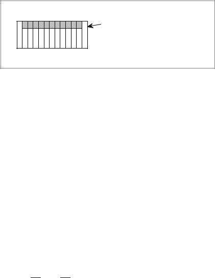
(10)The installation conditions of the I/O unit must be satisfied.
To obtain good ventilation in the module, the I/O unit must be installed in the direction shown in the following figure. Clearances of 100 mm or more both above and below the I/O unit are required for wiring and ventilation.
Equipment radiating too much heat must not be put below the I/O unit.
Top
I/O base unit
(No screws or protrusions shall extend from the bottom of this unit.)
Bottom
(11)If the CNC unit is installed at an elevation exceeding 1000 m, the upper limit temperature of the CNC inside the cabinet at the environmental conditions described in section 3.1 is subject to restrictions.
With each increase of 100 m above an elevation of 100 m, the upper limit temperature is reduced by 1°C.
Example) When the CNC unit is installed at an elevation of 1750 m, the allowable upper limit temperature of the CNC inside
the cabinet is calculated as follows: 55°C±1750/100 1.0°C+ 47.5°C
Accordingly the allowable temperature range is 0°C to 47.5°C
When a PCB with built±in hard disk is used, the installation elevation is restricted as follows:
Standard elevation when in operation: |
±60 to 3,000 m |
Standard elevation when not in operation: |
±60 to 12,000 m |
(12)In unspecified frequencies, the CNC control unit or the hard disk itself may resonate. If this happens, resonation may cause acceleration beyond the allowable limits of the devices. Full check this after installing the CNC control unit in the machine tool.
11

3. INSTALLATION |
B±62073E/04 |
|
|
NOTE
When a PCB with built±in hard disk is used, erroneous operation or unexpected accidents may damage the data stored on the hard disk even if the PCB is used under the correct environment. To be extra sure, back up important data from the hard disk.
If the power is turned OFF or a power interruption occurs during accessing of the hard disk or while the operating system is still running, data on the hard disk is more likely to be damaged. Avoid this at all costs. Also, instruct the end user to pay attention to this.
12

B±62073E/04 |
3. INSTALLATION |
|
|
3.4
THERMAL DESIGN OF THE CABINET
The purpose of the thermal design of the cabinet is to limit the difference in temperature between the air in the cabinet and the outside air to 10°C or less when the temperature in the cabinet increases.
The internal air temperature of the cabinet increases when the units and parts installed in the cabinet generate heat. Since the generated heat is radiated from the surface of the cabinet, the temperature of the air in the cabinet and the outside air balance at certain heat levels. If the amount of heat generated is constant, the larger the surface area of the cabinet, the less the internal temperature rises. The thermal design of the cabinet refers to calculating the heat generated in the cabinet, evaluating the surface area of the cabinet, and enlarging that surface area by installing heat exchangers in the cabinet, if necessary. Such a design method is described in the following subsections.
3.4.1 |
The cooling capacity of a cabinet made of sheet metal is generally 6 W/°C |
||
Temperature Rise |
per 1 m2 surface area, that is, when the 6 W heat source is contained in |
||
a cabinet having a surface area of 1 m2, the temperature of the air in the |
|||
within the Cabinet |
|||
cabinet rises by 1°C. In this case the surface area of the cabinet refers to |
|||
|
|||
|
the area useful in cooling , that is, the area obtained by subtracting the area |
||
|
of the cabinet touching the floor from the total surface area of the cabinet. |
||
|
There are two preconditions : The air in the cabinet must be circuited by |
||
|
the fun, and the temperature of the air in the cabinet must be almost |
||
|
constant. |
||
|
To calculate the increase in temperature inside the cabinet, the heat loss |
||
|
of the units to be installed must be checked. Section 3.4.3 lists the heat |
||
|
losses of the units provided by FANUC. The heat loss of all other parts |
||
|
in the cabinet must also be added. Let the obtained total heat loss be P |
||
|
[W]. |
||
|
The following expression must then be satisfied to limit the difference in |
||
|
temperature between the air in the cabinet and the outside air to 10°C or |
||
|
less as the temperature in the cabinet rises: |
||
|
Internal heat loss P [W]x 6 [W/m2´°C] surface area S [m2] |
||
|
10 [°C] of rise in temperature |
||
|
For example, a cabinet having a surface area of 4 m2 has a cooling capacity |
||
|
of 24 W/°C. To limit the internal temperature increase to 10°C under |
||
|
these conditions, the internal heat must not exceed 240 W. If the actual |
||
|
internal heat is 320 W, however, the temperature in the cabinet rises by |
||
|
13°C or more. When this happens, the cooling capacity of the cabinet |
||
|
must be improved using the heat exchanger described next. |
||
|
|
|
|
3.4.2 |
If the temperature rise cannot be limited to 10°C by the cooling capacity |
||
Cooling by Heat |
of the cabinet, a heat exchanger must be added. The heat exchanger |
||
forcibly applies the air from both the inside and outside of the cabinet to |
|||
Exchanger |
|||
the cooling fin to obtain effective cooling. The heat exchanger enlarges |
|||
|
|||
|
the surface area. Section 3.5 explains five heat exchangers supplied by |
||
|
FANUC. Select one of these according to the application. |
||
|
If cooling fin A is used for the cabinet, the total cooling capacity of a |
||
|
cabinet having a surface area of 4 m2 in the example above is improved |
||
|
as follows: |
||
13
3. INSTALLATION |
B±62073E/04 |
|
|
6 W/m2/°C |
4 m2) 9.1 W/°C+ 33.1 W/°C |
The calculated value verifies that even if the internal heat is 320 W, the temperature rise can be limited to less than 10°C.
See Section 3.5 for installing the heat exchanger.
3.4.3
Heat Loss of Each Unit
|
|
Name |
Heat |
Remarks |
|
|
loss |
||
|
|
|
|
|
|
|
|
|
|
Control unit |
Basic unit (4 slots) |
60W |
Power supply AI |
|
|
|
|
|
|
|
Basic unit (4 slots) |
80W |
Power supply BI |
|
|
|
|
|
|
|
Basic unit (6 slots) |
80W |
Power supply BI |
|
|
|
|
|
|
|
Basic unit (8 slots) |
80W |
Power supply BI |
|
|
|
|
|
|
|
Main CPU board |
20W |
|
|
|
|
|
|
|
|
PMC board |
18W |
|
|
|
|
|
|
|
|
Sub board |
18W |
|
|
|
|
|
|
|
|
Option 1 board |
15W |
|
|
|
|
|
|
|
|
RISC Board |
18W |
Cannot be used on |
|
|
|
|
|
15TED/15TEE/15TEF/15MEK/15MEL |
|
|
|
|
|
|
Buffer board (Multiple axis) |
6W |
|
|
|
|
|
|
|
|
AXES CPU (Multiple axis) |
15W |
|
|
|
|
|
|
|
|
MMC±II CPU board |
20W |
Can be used only on series 150±B |
|
|
|
|
|
|
|
MMC±II Graphic board |
20W |
Can be used only on series 150±B |
|
|
|
|
|
|
|
MMC±III CPU board |
20W |
Can be used only on series 150±B |
|
|
|
|
|
|
|
MMC±IV CPU board |
15W |
Can be used only on series 150±B |
|
|
|
|
|
|
|
OSI/Ethernet board |
18W |
Cannot be used on |
|
|
|
|
|
15TED/15TEE/15TEF/15MEK/15MEL |
|
|
|
|
|
|
Data server board |
18W |
|
|
|
|
|
|
|
|
HSSB interface board |
3W |
Can be used only on series 150±B |
|
|
|
|
|
|
CRT/MDI |
9″ |
monochrome CRT/MDI |
14W |
For both small and standard type |
|
|
|
|
|
|
9″ |
color CRT/MDI |
38W |
For both small and standard type |
|
|
|
|
|
|
9″ |
monochrome PDP/MDI |
20W |
For both small and standard type |
|
|
|
|
|
|
10.4″ color LCD/MDI |
20W |
For both graphic function built±in type and MMC±IV |
|
|
|
|
|
|
|
9.5″ color LCD/MDI |
20W |
|
|
|
|
|
|
|
|
14″ color CRT/MDI |
70W |
|
|
|
|
|
|
|
|
9.5″ LCD (monochrome STN) |
10W |
|
|
|
|
|
|
|
14

B±62073E/04 |
|
|
|
|
|
|
3. INSTALLATION |
|
|
|
|
|
|
|
|
|
|
|
|
|
|
|
|
|
|
|
|
Name |
Heat |
|
|
|
|
Remarks |
|
|
loss |
|
|
|
|
|||
|
|
|
|
|
|
|
||
|
|
|
|
|
|
|
|
|
Connection unit |
Connection unit 1 |
35W |
|
|
|
|
|
|
|
|
|
|
|
|
|
|
|
|
Connection unit 1+2 |
60W |
|
|
|
|
|
|
|
|
|
|
|
|
|
|
|
Operator's |
Operator's panel connection unit |
30W |
|
|
|
|
|
|
panel |
|
|
|
|
|
|
|
|
|
|
|
|
|
|
|
|
|
I/O unit |
AIF01A, AIF01B |
1.2W |
|
|
|
|
|
|
model A |
|
|
|
|
|
|
|
|
AID32A, AID32B |
1.2W) |
0.23W number of ON points |
||||||
|
||||||||
|
|
|
|
|||||
|
AID16A, AID16B |
0.1W) |
0.21W number of ON points |
|||||
|
|
|
|
|||||
|
AID32E, AID32F |
0.1W) |
0.23W number of ON points |
|||||
|
|
|
|
|
|
|
|
|
I/O unit |
BIF04A1 |
1.6W |
|
|
|
|
|
|
model B |
|
|
|
|
|
|
|
|
AIF02C |
1.2W |
|
|
|
|
|
||
|
|
|
|
|
|
|||
|
|
|
|
|||||
|
BID16A1, BID16B1 |
1.5W) |
0.23 number of ON input points |
|||||
|
|
|
|
|||||
|
BID16P1, BID16Q1 |
0.6W) |
0.23 number of ON input points |
|||||
|
|
|
|
|
|
|
||
|
BOA12A1 |
0.9W) |
(0.09 |
1.1 |
IL2) |
number of ON output points |
||
|
BOD16A1 |
1.0W) |
(0.13+0.3 |
IL2) |
number of ON output points |
|||
|
BOD16P1 |
0.3W) |
(0.13+0.3 |
IL2) |
number of ON output points |
|||
|
BIA16P1 |
0.1W) |
0.21 number of ON input points |
|||||
|
|
|
|
|||||
|
BMD88A1, BMD88B1 |
1.3W) |
0.23 number of ON input points) |
|||||
|
|
(0.13) |
0.3 |
IL2) |
number of ON output points |
|||
IL: load current |
BMD88P1, BMD88Q1 |
0.4W) |
0.23 number of ON input points) |
|||||
of output |
|
(0.13) |
0.3 |
IL2) |
number of ON output points |
|||
MMC±II |
Hard disk unit |
26W |
|
|
|
|
|
|
|
|
|
|
|
|
|
|
|
|
Panel mount type 3.5″ floppy disk |
3W |
|
|
|
|
|
|
|
unit |
|
|
|
|
|
|
|
|
|
|
|
|
|
|
|
|
|
Portable type 3.5″ floppy disk unit |
12W |
|
|
|
|
|
|
|
|
|
|
|
|
|
|
|
|
Portable type 5.25″ floppy disk unit |
26W |
|
|
|
|
|
|
|
|
|
|
|
|
|
|
|
|
Full±key board unit |
2W |
|
|
|
|
|
|
|
|
|
|
|
|
|
|
|
|
Extention adapter unit |
7W |
|
|
|
|
|
|
|
|
|
|
|
|
|
|
|
|
Portable cassette streamer unit |
24W |
|
|
|
|
|
|
|
|
|
|
|
|
|
|
|
Multi±tap transformer |
51W |
|
|
|
|
|
||
|
|
|
|
|
|
|
|
|
See FANUC SERVO AMPLIFIER α series DESCRIPTIONS (B±65162E) for heat loss of servo amplifier.
15
3. INSTALLATION |
B±62073E/04 |
|
|
3.5
INSTALLING THE HEAT EXCHANGER
Table 3.5 lists the heat exchangers.
Cooling fins A, B and C are not provided with a fan. Note that a fan motor is required for any of these cooling fins when it is used as a heat exchanger.
Table 3.5 List of heat exchangers
Name |
Ordering |
Cooling |
|
Size |
|
specification |
capacity |
|
|||
|
|
|
|
||
|
|
|
|
|
|
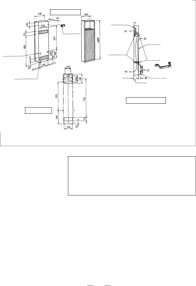
Cooling fin A |
A02B±0053±K303 |
9.1 W/°C |
196 |
90 |
1000 mm |
|
|
|
|
|
|
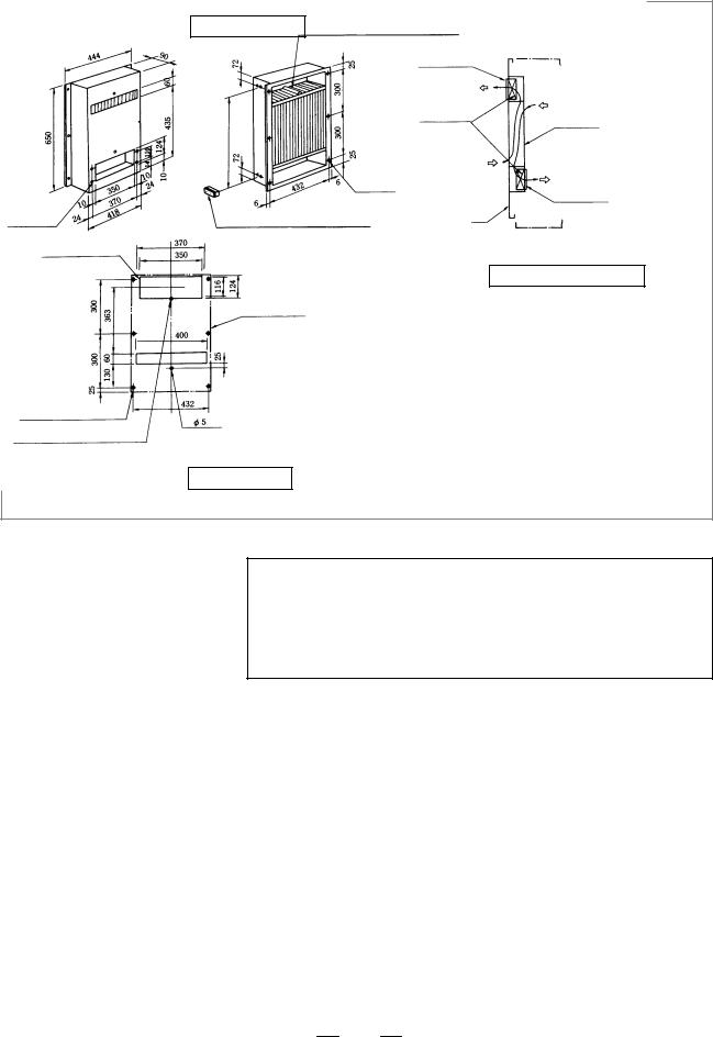
Cooling fin B |
A02B±0053±K304 |
10.1 W/°C |
444 |
90 |
650 mm |
|
|
|
|
|
|
Cooling fin C |
A02B±0053±K305 |
25.2 W/°C |
560 |
90 |
970 mm |
|
|
|
|
|
|
Heat exchanger for |
A02B±0060±K401 |
5.0 W/°C |
390 |
86 |
480 mm |
CRT/MDI unit |
|
|
|
|
|
|
|
|
|
|
|
Heat pipe type heat |
A02B±0094±C901 |
9.0 W/°C |
226 |
132 |
415 mm |
exchanger |
|
|
|
|
|
|
|
|
|
|
|
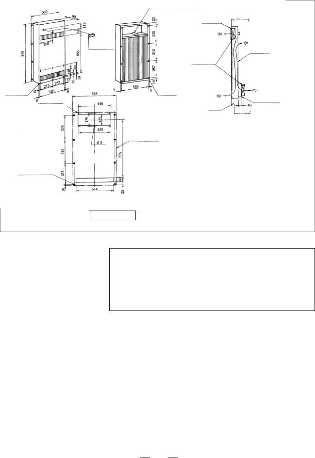
3.5.1
Cooling Fin A/B/C
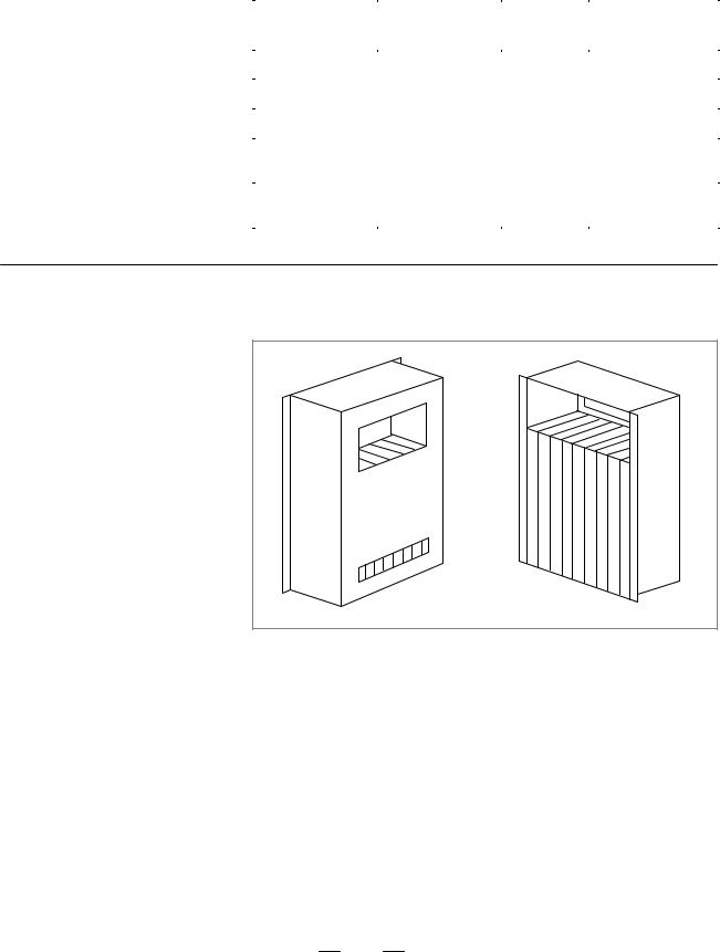
The cooling fin is shown below (Fig. 3.5.1 (a)). It is installed in a cabinet made by the machine tool builder.
Viewed from cabinet mounting side
Fig. 3.5.1 (a) External view of cooling fin
16

B±62073E/04 |
3. INSTALLATION |
|
|
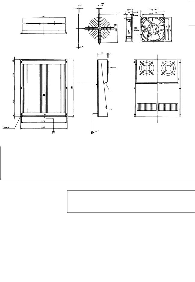
Cabinet
Cooling fin
Inside air flow
Outside air flow
Fig. 3.5.1 (b) Internal view of cooling fin
The cooling fin can be installed in two ways, as shown in Fig. 3.5.1 (b). The following lists the general precautions to be observed when using the cooling fins :
1)The fans are not included with the cooling fin. They should be provided by the machine tool builder.
2)Bring in the outside air from the bottom and exhaust the hot air from the top.
3)The inside air may flow from top to bottom or bottom to top. However, generally decide the direction as follows :
a)Bring in the air near high heat loss components.
b)Exhaust the air toward the most important components to be cooled.
4)For the cooling fin to display the specified cooling capacity, the air inside the cooling fins must flow at a velocity of 2.5 m/sec or greater. (velocity of air flow measurement)
Set the slit to the intake side and measure the velocity at the slit.
5)Generally, install the cooling fins to the door. But be sure that the door does not bend when installing the cooling fin. The cooling fins are equipped with packing.
17
3. INSTALLATION |
B±62073E/04 |
|
|
External dimensions
|
Terminal |
|
|
block for fan |
|
|
motor G±04 |
|
|
(Attached to |
|
Mounting metals |
the cooling fins. |
|
Its height is 20 |
||
for cooling fins |
||
mm) |
||
4±M4 |
||
|
||
Mounting screw |
|
|
4±M4 |
|
|
Mounting screw |
|
|
for fan mounting plate |
|
Panel cut drawing
Fan mounting plate
Fan motor
Door
Cooling fins |
|
Mounting metal |
|
for cooling fins |
|
|
Mounting metal |
Mounting plate |
for cooling fins |
for fan motor |
(sheet metal |
|
about 3 mm |
|
thick). |
Mounting diagram (example)
Fig. 3.5.1 (c) External dimension mounting method of cooling fin A (A02B±0053±K303)
NOTE
1Fan motor, mounting plate for fan motor and mounting metal for cooling fins are not attached to the cooling fins.
So, prepare them at the machine tool builder.
2Use two fan motors with about 50 W power.
3Weight: 6.5 kg
18
B±62073E/04 |
3. INSTALLATION |
|
|
Mounting hole for fan motor 4±M4
4±M4 (Mounting hole for fan motor)
6±6 dia hole or M5 stud bolt
Stud hole
(Make a hole 5 dia for fan motor)
External dimensions
Mounting stud for cooling fins
(2 studs are attached top and bottom)
Mounting hole for fan motor
|
Fan motor |
Cooling fins |
|
|
|
6±6 dia. |
|
|
Mounting hole |
Mounting |
|
|
|
|
|
|
plate for fan |
Terminal block for fan motor G±04 |
Door |
motor |
|
||
(Attached to the cooling fins. Its height is 20 mm)
Mounting diagram (example)
Hole
External shape of cooling fins.
Hole
Panel cut drawing
Fig. 3.5.1 (d) External dimension mounting method of cooling fin B (A02B±0053±K304)
NOTE
1Fan motor and mounting plate are not attached to the cooling fins. So, prepare them, at the machine tool builder.
2Use four fan motors with about 20 W power.
3Weight: 7.5 kg
19
3. INSTALLATION |
B±62073E/04 |
|
|
|
External dimensions |
Mounting stud for cooling fins |
|
|
|
|
|
|
|
|
|
|
|
(Attached to the cooling fins) |
|
|
|
|
|
|
|
||
|
|
Mounting plate |
|
|
|
|
|
for fan motor |
|
|
|
|
Terminal block |
|
|
|
|
|
for fan motor |
|
|
|
|
|
G±04 |
|
|
Cooling fins |
|
|
(Attached to |
|
|
||
|
|
|
|
|
|
|
the cooling |
Fan motor |
|||
|
fins.Its height |
||||
|
|
|
|
|
|
|
is 20 mm) |
|
|
|
|
6±M4 |
|
8±6 dia. |
|
|
|
Mounting hole |
|
Mounting |
|||
|
Mounting hole |
||||
for fan motor |
|
plate for fan |
|||
|
|
|
|||
5±M4 |
|
|
|
motor |
|
(Mounting hole |
|
Door |
|
|
|
for fan motor) |
|
|
|
||
|
|
|
|
|
|
|
|
|
|
Mounting diagram (example) |
|
|
|
External shape |
|
|
|
|
|
|
|
|
|
|
|
of cooling fins. |
|
|
|
|
(This hole com- |
|
|
|
|
|
bines mounting |
|
|
|
|
6±6 dia hole or |
hole and stud |
|
|
|
|
hole.) |
|
|
|
|
|
M5 stud bolt |
|
|
|
|
|
Panel cut diagram
Fig. 3.5.1 (e) External dimension and mounting method of cooling fin C (A02B±0053±K305)
NOTE
1 Fan motor and mounting plate for fan motor are not attached to the cooling fins. Prepare them at the machine tool builder.
2Use two fan motors with about 40 W power.
3Weight: 13.5 kg
20
B±62073E/04 |
3. INSTALLATION |
|
|
3.5.2
Heat Exchanger for CRT/MDI Unit
hole
|
Lot |
|
No. |
|
Weight: 0.65 kg |
External Dimensions of |
External Dimensions of External |
Finger Guard |
Cooling Fan |
Air inlet
Packing
Power terminal M4 screw AC200 V 50 Hz AC200 V/220 V 60 Hz
48 W
Air outlet
Connector for external cooling fan
Cooling fin: About 6 kg (Excluding attached parts)
Fig. 3.5.2 (a) External dimensions of external cooling fan and cooling unit for CRT/MDI (A02B±0060±K401)
NOTE
External cooling fan and finger guard are attached beside cooling fin.
21

3. INSTALLATION |
B±62073E/04 |
|
|
Heat exchanger
Outside Inside
Air outlet
Air outlet
Main body of heat exchanger
(1)
Air inlet
Prepare mounting |
|
screws and mount- |
External cooling fan (attached) |
ing panel. |
|
|
Finger guard (attached) |
(1)Use M5 screws to mount the heat exchanger.
(2)Be careful with air flow when securing the external cooling fan.
(3)Prepare a mounting panel for external cooling fan and install the panel where it can be exchanged externally.
(4)Drill mounting holes for external cooling fan and air outlet on heat exchanger mounting panel.
Fig. 3.5.2 (b) Mounting methods of heat exchanger for CRT/MDI
22
|
B±62073E/04 |
|
|
|
3. INSTALLATION |
||
|
|
|
|
|
|
|
|
|
|
|
|
|
|
|
|
|
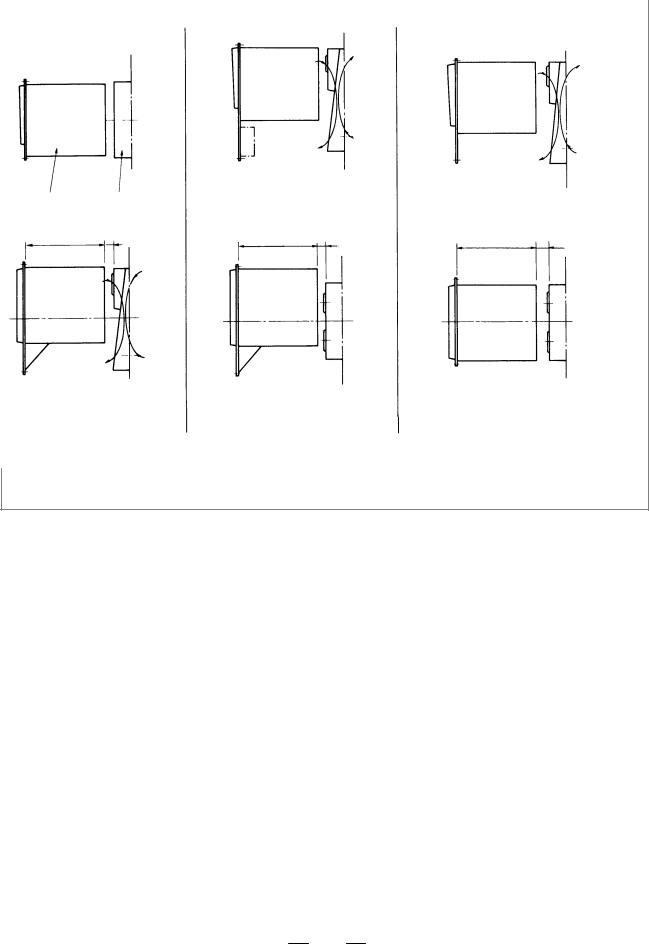
Horizontal type CRT/MDI only |
Horizontal type CRT/MDI |
Vertical type CRT/MDI only |
||||
|
and machine operator's panel |
||||||
|
|
|
|
|
|
||
|
Inside |
Outside |
|
|
|
|
|
|
Side view |
|
|
|
|
|
|
|
CRT/MDI |
Heat exchanger |
|
|
|
|
|
|
|
Min |
|
Min |
|
Min |
|
|
370 |
35 |
|
35 |
|
||
|
370 |
370 |
35 |
|
|||
|
|
|
|
|
|
|
|
Top view
Refer to these figures for allocation of CRT/MDI and heat exchanger.
Fig. 3.5.2 (c) Allocation of 14″ color CRT/MDI and heat exchanger
23
 Loading...