


 Loading...
GE Fanuc Automation Europe
Computer Numerical Controls
Laser-Model C1000 iA
Operator’s Manual
B-70254EN/01
TECHNOLOGY AND MORE

•No part of this manual may be reproduced in any form.
•All specifications and designs are subject to change without notice.
The products in this manual are controlled based on Japan’s “Foreign Exchange and Foreign Trade Law”. The export from Japan may be subject to an export license by the government of Japan.
Further, re-export to another country may be subject to the license of the government of the country from where the product is re-exported. Furthermore, the product may also be controlled by re-export regulations of the United States government.
Should you wish to export or re-export these products, please contact FANUC for advice.
In this manual we have tried as much as possible to describe all the various matters. However, we cannot describe all the matters which must not be done, or which cannot be done, because there are so many possibilities.
Therefore, matters which are not especially described as possible in this manual should be regarded as ”impossible”.
This manual contains the program names or device names of other companies, some of which are registered trademarks of respective owners. However, these names are not followed by ® or ™ in the main body.
B-70254EN/01 |
TABLE OF CONTENTS |
TABLE OF CONTENTS
! " #
$
$ % & ! ' !
$ ( ! )
$ (
$ ( ' * &$ $ % & + ,
-
- . / & ! ' ! $- / $
|
|
|
|
$ |
|
|
$ |
! |
c - 1
TABLE OF CONTENTS |
B-70254EN/01 |
$ |
|
" |
|
"
# !
$
-
0 |
|
|
|
# |
! |
$% !
!
# !!
!
$
- $%
"
0 $%
!
c - 2

B-70254EN/01 |
1.OVERVIEW |
1 OVERVIEW
This manual describes how to handle the FANUC LASER-MODEL C1000iA for those users who operate laser oscillators.
In this manual, we have tried as for as possible to address all issues. However, space restrictions prevent us from describing everything that must not be done,
or which cannot be done, because there are so many possibilities. Therefore, all matters which are not specifically described as being possible should be regarded as being "impossible".
- 1 -

1.OVERVIEW |
B-70254EN/01 |
1.1 MANUAL CONTENTS
This manual consists of the following chapters and appendixes:
1.OVERVIEW
Chapter 1 covers the configuration of the manual, applicable models, related manuals, and provides notes on reading the manual.
2.SAFETY
Chapter 2 covers the warnings and precautions related to laser beams, high voltages, high temperatures, and a toxic substances. To ensure safe operation, read this chapter first.
3. FUNCTIONS
Chapter 3 describes the structure and operation of the laser oscillator.
4. MAINTENANCE
Chapter 4 describes the periodic maintenance of the laser oscillator.
5. TROUBLESHOOTING
Chapter 5 describes the actions to be taken if the oscillator malfunctions.
APPENDIX
A.EXTERNAL VIEW
B.FANUC LASER C SERIES SPECIFICATIONS
C.ERROR CODE LIST
D.GLOSSARY
- 2 -

B-70254EN/01 |
1.OVERVIEW |
1.2 APPLICABLE MODELS
This manual covers the following models:
Model
FANUC LASER-MODEL C1000iA
Abbreviation
C1000iA
- 3 -

1.OVERVIEW |
B-70254EN/01 |
1.3 RELATED MANUALS
The following manuals are available for the FANUC LASER-
MODEL C1000iA:
FANUC Series 16i-LA
FANUC LASER-MODEL C1000iA
DESCRIPTIONS |
B-63192EN |
|
CONNECTION MANUAL |
B-63193EN |
|
OPERATOR’S MANUAL |
B-63194EN |
|
MAINTENANCE MANUAL |
B-63195EN |
|
PARAMETER MANUAL |
B-63200EN |
|
DESCRIPTIONS |
B-70252EN |
|
OPERATOR’S MANUAL |
B-70254EN |
|
(This manual) |
||
|
||
MAINTENANCE MANUAL |
B-70255EN |
- 4 -

B-70254EN/01 |
1.OVERVIEW |
1.4 FOR SAFE OPERATION
This manual contains precautions which must be observed during operation of the laser oscillator, to ensure the operator’s safety and prevent damage to the oscillator. Each precaution is indicated by "Warning" or "Caution" according to its severity.
Supplementary information is indicated by "Note".
Read the contents of each "Warning", "Caution", and "Note" before attempting to use the oscillator.
WARNING
Precautions to be applied in those situations where there is a danger of the operator being killed or seriously injured.
CAUTION
Precautions to be applied in those situations where there is a danger of the operator being slightly injured or the oscillator being damaged.
NOTE
Supplementary information other than precautions.
The functions of a laser machining system depend not only on the laser oscillator, but also on the machine, power magnetics cabinet, servo system, CNC, and operator’s panel. This manual describes only the laser oscillator. For a description of the other components, refer to the corresponding manuals, supplied by the machine tool builder.
- Read this manual thoroughly and store it in a safe place.
- 5 -

2.SAFETY |
B-70254EN/01 |
2 SAFETY
This chapter describes precautions to be observed to ensure the safe operation of the laser oscillator.
Read this chapter thoroughly before attempting to use the laser oscillator.
Also, read the safety precautions in the operator’s manual supplied by the machine tool builder.
The laser oscillator may present a danger not only to the operator but also to other people working around the oscillator, up to a considerable distance away. The laser oscillator must, therefore, be operated only by a person who has received appropriate training.
Only persons who have understood the internal structure of the laser oscillator and have received appropriate training can maintain the laser oscillator.
A warning label is put on each dangerous position of the laser oscillator. Be extremely careful about the labeled positions.
- 6 -
B-70254EN/01 |
2.SAFETY |
2.1 WARNING
(1)It is extremely dangerous to expose your eyes to direct, scattered, or reflected CO2 laser light. Always wear protective glasses while the laser is operating.
Exposure to laser light can cause blindness. If your eyes are accidentally exposed, seek medical advice immediately.
(2)Do not turn on the laser oscillator while a panel is removed or a door is open.
Operating the laser with a door open or panel removed may result in the operator being directly exposed to CO2 laser radiation. Exposure to laser light can cause blindness and/or severe burns. If your eyes are accidentally exposed to laser light, seek medical advice immediately.
Before turning on the power during maintenance if absolutely necessary, wear protective glasses and clothing to prevent accidents.
(3)If the laser oscillator is operated with a panel open, ultraviolet radiation is emitted from the high-frequency discharge section. Gazing the discharge section for a long time can cause visual disturbances such as impaired eyesight.
Always wear protective glasses during work. If you feel trouble with your eyes, seek medical advice immediately.
(4)Surround the laser machining tool with a fence made of a material which absorbs laser light well (such as acrylic). Place appropriate warning notices on the fence.
The door in the safety fence shall be fitted with an interlock switch such that opening the door stops the laser.
Failure to provide such a fence exposes persons in the vicinity of the machine tool to the danger of being exposed to CO2 laser radiation and the associated risk of blindness. If a person is accidentally exposed to laser light, seek medical advice immediately.
(5)The laser beam shall be no higher than average eye height. Enclose the path of the laser beam with covers. Do not leave the end of the beam path open. Place laserabsorbing material at the end of the beam path to absorb the beam’s energy.
A CO2 laser beam is directional and has a high energy density. Exposure to laser light can cause blindness. Flammable material may burn or explode if exposed to the laser beam. If your eyes are accidentally exposed to laser light, seek medical advice immediately.
- 7 -
2.SAFETY |
B-70254EN/01 |
(6)A high voltage of 3 to 4 kV0-p is applied to some places in the laser oscillator cabinet. Therefore, do not turn the power to the oscillator on or operate the oscillator when an oscillator panel is open. Operating the laser oscillator with a panel open can cause a touch on a high-voltage place, resulting in electric shock. Before turning on the power during maintenance if absolutely necessary, take measures against accidents.
(7)Before daily inspection, the replacement of a maintenance part or maintenance, open the main circuit breaker and turn the power supply off (double power-off).
To prevent the power from being inadvertently turned on, lock the circuit breaker open, and affix an indication of work in progress.
Failure to turn off the power during inspection or replacement exposes the operator to the danger of electric shock.
Before turning on the power during maintenance if absolutely necessary, take measures against accidents.
(8)The oscillator output mirror and focusing lens on the machining head both have a substrate made of ZnSe (zinc selenide), a toxic substance. Therefore, do not touch the mirror or lens with your bare hands.
Inhaling ZnSe dust may cause difficulty in breathing, completely stopping the breathing of the victim in the worst case.
If you accidentally touch the mirror or lens with your bare hands, wash your hands well under running water.
If you accidentally inhale ZnSe dust or debris, seek medical advice immediately.
(9)Do not look at the machining point without eye protection. Otherwise, your eyes may be exposed to reflected laser light, resulting in blindness.
If your eyes are accidentally exposed to laser light, seek medical advice immediately.
(10)Before attempting to machine any material for the first time, consult with the manufacturer of the material.
Some materials generate toxic gases when cut or drilled by a laser beam.
Should you accidentally inhale any toxic gas, seek medical advice immediately.
(11)If the laser oscillator must be moved, entrust the work to the machine tool builder whenever possible. If performed by inexperienced personnel, the oscillator may topple or be dropped, resulting in a potentially fatal accident.
When the machine tool builder is not available to move the oscillator, follow the procedure described on the hanging method label. While moving the oscillator, stand well clear and never pass under the oscillator.
- 8 -
B-70254EN/01 |
2.SAFETY |
(12)Do not allow any dangerous or high-pressure gas to get into the oscillator housing. The oscillator cabinet has a hermetic structure (dustproof and dripproof), it cannot be ventilated easily.
Flammable gases such as oxygen can cause a fire or explosion. Toxic gases can harm operators during maintenance. Organic gases can degrade machining performance. High-pressure gases can damage a panel or the cabinet, resulting in injury from flying matters.
If such a gas accidentally gets into the oscillator housing, remove a panel for ventilation. The installation room must be also well ventilated.
To purge the oscillator housing, use purified, low-pressure air or nitrogen.
- 9 -

2.SAFETY |
B-70254EN/01 |
2.2 CAUTION
(1)If there is a possibility of being exposed to CO2 laser radiation exceeding the maximum permissible exposure (MPE) level for skin, wear protective clothing.
Otherwise, there is a danger of being burnt.
(2)FANUC LASER-MODEL C1000iA is fitted with a red semiconductor laser to indicate the approximate position of invisible CO2 laser beam. Do not look directly at the semiconductor laser beam. Otherwise, your eyes may be injured.
(3)The gas circulating system in the oscillator becomes very hot. Do not touch the gas pipes, turbo blower, heat exchanger, or exhaust pump, until they have cooled down sufficiently after the oscillator has been turned off. Otherwise, you may be burnt.
(4)Do not pass your hand in the optical path of the laser machine or under the laser head when the shutter of the oscillator is open. When the shutter is open, a laser beam may be emitted from the oscillator accidentally. Before work in the optical path or under the laser head, confirm that the shutter is closed.
(5)The workpiece becomes very hot during machining. Never touch the workpiece with your bare hands. Otherwise, you may be burnt.
(6)During machining, extremely hot chips are likely to be generated.
Unless sufficient caution is exercised, there is a danger of the operator being burnt, or of a fire being started.
(7)Some materials may burn or explode when laser machined. Before attempting to machine any material for the first time, consult with the manufacturer of the material, to prevent the danger of fire of or the possibility of operator injury.
(8)The oscillator contains cooling fan units. Although the fan units are fitted with a finger guard, to prevent injury, keep your hands well away from the fans.
(9)The oscillator is controlled according to the CNC internal parameter settings. If a numeric value different from a setting is entered and the oscillator is operated, the oscillator may malfunction. In the worst case, the oscillator may be damaged.
- 10 -

B-70254EN/01 |
2.SAFETY |
2.3 NOTE
(1)During installation or maintenance necessitating the opening of an oscillator door or the removal of a panel, only persons who have undergone maintenance training should operate the laser. In such a case, extreme caution must be exercised.
(2)Warning labels are affixed to those parts of the oscillator where there is a danger of exposure to laser radiation. Observe the precautions given on the labels. (Section 2.4 shows the warning labels.)
(3)Laser products shall conform to the regulations laid down in the laser safety standard, including that stipulating control using a key.
The oscillator start signal (RUN ON) shall be controlled with a key switch such that the oscillator cannot be turned on without a specific key.
Control using a key ensures that other than the authorized personnel cannot operate the laser oscillator. It is extremely dangerous if a person who is unfamiliar with the equipment attempts to operate the laser oscillator.
(4)The shutter shall be unlocked only while a beam is being output. Otherwise, keep the shutter locked to provide protection should the laser accidentally be turned on.
(5)Do not discard a used output mirror or focusing lens together with regular waste. If the output mirror or focusing lens is replaced, return the original to the supplier or entrust it to a specialized disposal company.
(6)Do not place any flammable material (such as paper, cloth, or wood) near the workpiece table.
(7)Keep a fire extinguisher beside the unit.
(8)The FANUC LASER-MODEL C1000iA is equipped with an alarm lamp. The alarm lamp blinks while discharge is in progress or whenever laser radiation is possible.
While the alarm lamp is blinking, pay careful attention to laser radiation and high voltages.
- 11 -
2.SAFETY |
B-70254EN/01 |
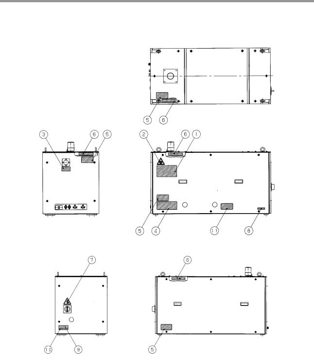
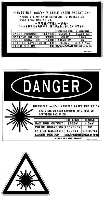
2.4 WARNING LABELS
The oscillator uses high voltages and laser beam radiation. Such hazards are indicated with warning labels attached to the positions shown in Fig. 2.4 (a) to (b).
Fig. 2.4 (a) Warning label positions (C1000iA : front view)
Fig. 2.4 (a) Warning label positions (C1000iA : rear view)
- 12 -
B-70254EN/01 |
2.SAFETY |
(1) Class indication label (JPN)
(1) Class indication label (FDA)
(2) Warning label
- 13 -
2.SAFETY |
B-70254EN/01 |
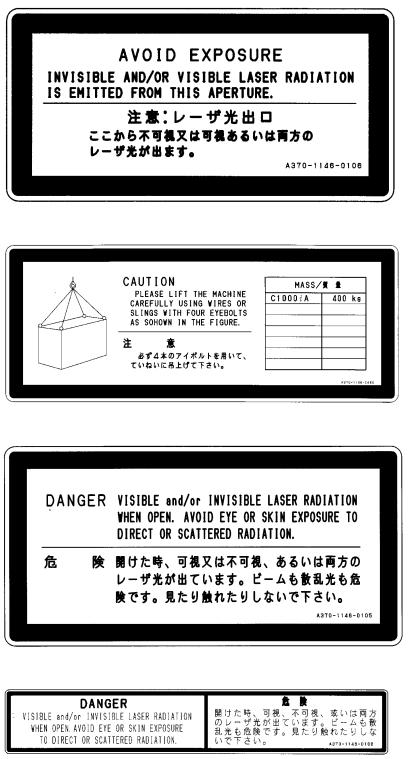
(3) Aperture label
(4) Suspension method label
(5) Access panel
(6) Label inside the access panel
- 14 -
B-70254EN/01 |
2.SAFETY |
(7) Discharge section label
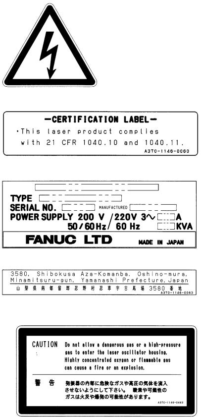
(8) Certification label
(9) Equipment nameplate
(10) Manufacturer’s address label
$% Label for regulating the atmospheric gases in the oscillator housing
- 15 -

3.INTERNAL STRUCTURE |
B-70254EN/01 |
3 INTERNAL STRUCTURE
- 16 -
B-70254EN/01 |
3.INTERNAL STRUCTURE |
3.1 OUTLINE
Fig. 3.1 show the internal structure of the laser oscillator.
The C1000iA consists of a laser resonator, discharge drive unit, forced gas circulating system, pressure controller, CNC interface, and a protective housing.
Fig. 3.1 C1000iA internal structure
(1)Laser resonator
The laser resonator consists of several discharge tubes, connected in series using folding mirrors, with a rear mirror and output mirror placed at the open ends of the discharge tubes, thus sealing the tubes. The resonator is fitted with a gas pipe connecting port through which laser gas is fed into the discharge tubes.
A discharge from the electrodes of the discharge tube energizes CO2 molecules, which emit light. This light is amplified by stimulated emission, repeated between the rear mirror and output mirror, a laser beam being emitted from the output mirror.
- 17 -
3.INTERNAL STRUCTURE |
B-70254EN/01 |
(2)Discharge drive unit
The discharge drive unit consists of a laser power supply, matching box, and discharge tubes. High-frequency output of 2 MHz that is controlled by the CNC discharges the laser gas flows through discharge tubes to energize CO2 molecules.
(3)Forced gas circulating system
A gas circulating system is configured by connecting the resonator and turbo blower with a circulating pipe. Laser gas is forced through the discharge tubes at a speed of 200 m/s or higher.
A water-cooled heat exchanger, used to cool the hightemperature gas from the discharge tubes, is provided at the inlet side of the turbo blower. At the outlet side of the turbo blower, another water-cooled heat exchanger dissipates the compression heat.
(4)Pressure controller
The laser gas pressure within the forced gas circulating system is controlled by commands issued from the CNC, thus ensuring stable laser output.
(5)CNC interface
Interface used to connect a FANUC Series 16i-L. CNC commands that, control the operation of the laser oscillator, such as start/stop and laser output, are input via this interface.
(6)Protective housing
An enclosure that houses the above components. The housing, consisting of metal panels, completely encloses the laser oscillator, thus protecting the operator from exposure to laser radiation and from high voltages. All panels are screw-fixed and cannot be removed without an appropriate tool.
- 18 -

B-70254EN/01 |
3.INTERNAL STRUCTURE |
3.2 COMPONENT DETAILS
This section describes the internal structure of the C1000iA more specifically. Fig. 3.2 is an internal structural drawing.
Fig. 3.2 C1000iA structural drawing
(1)Resonator
The resonator consists of an output mirror, rear mirror, folding mirrors, discharge tubes, power sensor unit, etc. It converts
electrical energy first to laser gas, then to optical energy (10.6-m single-wavelength laser beam).
(2)Output mirror
A transmitting/reflecting mirror which outputs the laser beam after it has been amplified. The output mirror consists of a ZnSe (zinc selenide) substrate, coated with dielectric. ZnSe is tightly toxic. Be particularly careful, therefore, when handling the output mirror.
- 19 -
3.INTERNAL STRUCTURE |
B-70254EN/01 |
(3)Rear mirror
A reflecting mirror consisting of a Ge (germanium) substrate, coated with dielectric.
Having a high reflectance of 99.5%, the rear mirror is used to reflect the laser beam within the resonator while transmitting 0.5% of the laser light so that the beam can be monitored externally.
(4)Folding mirror
A mirror unit which reflects the laser beam at a 90-degree angle. The folding mirror consists of a block with a surface tilting to a 45-degree angle and an Si (silicon) substrate, coated with multilayer dielectric film.
(5)Discharge tube
A pair of Ag (silver) electrodes are metallized on the surface of a hollow quartz glass pipe. A high-frequency discharge between these electrodes injects electrical energy into the laser gas. Each electrode is coated with ceramic, preventing it from degrading and thus improving system reliability.
(6)Trigger electrode
A predischarge placed outside the laser oscillation area can facilitate the start of the main discharge. With it, the laser output is completely zero when the beam is off.
(7)Power sensor
An optical sensor which detects the intensity of the laser beam, transmitted through the rear mirror, thus enabling monitoring of the laser output level.
(8)Gas circulating system
A gas circulating path including a turbo blower, heat exchangers, and circulating pipes, which circulates laser gas in the discharge tubes at high speed.
(9)Turbo blower
During laser oscillation, the laser gas pressure is 1330 – 9310 Pa. The turbo blower circulates this rough-vacuum gas at high speed without contaminating the gas.
(10)Heat exchanger (inlet)
Water-cooled heat exchanger used to cool the laser gas that has been heated by discharge, before it is drawn into the turbo blower.
(11)Heat exchanger (outlet)
Water-cooled heat exchanger used to cool the laser gas that has been heated by compression in the turbo blower, before being forced into the discharge tubes.
- 20 -
B-70254EN/01 |
3.INTERNAL STRUCTURE |
(12)Gas controller
The gas controller always monitors the gas pressure in each discharge tube and supplies the fresh laser gas to the circulating system to keep the pressure constant. It also monitors the supply status of the laser gas, purge check for the circulating system, and other items and has a function of adjusting the amount of flow of the gas to be exhausted.
(13)Exhaust pump unit
This unit is used to vacuum-exhaust laser gas from the gas circulating system such that its pressure falls to that used for laser oscillation. Also, within this unit, a small amount of circulating gas is constantly being exchanged, to prevent degradation of the circulating gas.
(14)Hour meter
The hour meter indicates the total number of hours that the laser oscillator has operated (how many hours the exhaust pump has operated), to indicate whether maintenance or inspection is necessary.
(15)Shutter
The shutter has a rotary arm operated by a rotary solenoid and an Au (gold)-evaporated reflecting mirror attached to the arm.
It can be opened and closed by CNC commands. It also has a position sensor and a temperature sensor for safety and always monitors the open/close status and shutter temperature.
(16)Beam absorber
While the laser oscillator is operating with the shutter closed, the laser beam is guided into the beam absorber. The beam absorber absorbs nearly 100% of laser beam and is water-cooled, allowing it to safely absorb the beam for relatively long periods. For safety, the beam absorber is equipped with a temperature sensor which allows the system to monitor the temperature of the beam absorber.
(17)Distribution unit
This unit distributes cooling water, supplied from either a chiller unit or a temperature-regulated external water supply, to each unit in the laser oscillator.
For safety, the water distribution unit is equipped with a flow sensor which allows the system to monitor the flow rate of the cooling water.
- 21 -
3.INTERNAL STRUCTURE |
B-70254EN/01 |
(18)Laser power supply
A power supply for generating a discharge in each discharge tube. The laser power supply receives the three-phase AC input at 200/220V and outputs 2-MHz high-frequency power controlled with stability by commands from the CNC.
The RF inverter converts DC power to 3 to 4 kVPO-P highfrequency (2 MHz) power, then outputs it to the matching box.
(19)Matching box
The matching box contains a matching circuit, consisting of coils and capacitors, which ensures that power is effectively input to the discharge tubes.
(20)Intermediate PCB B
This PCB transmits signals output by the shutter section, such as those from the limit switch, absorber temperature sensor, power sensor, and condensation sensor, to the interface PCB.
(21)Input unit
The power magnetics cabinet distributes power, supplied from an external unit, to each unit in the laser oscillator. It also protects each unit from overcurrents.
(22)Input unit control PCB
This PCB has functions of transmitting the contactor open/close signals according to CNC commands and of notifying the CNC of the open/close status of the circuit breaker in the input unit.
(23)Interface PCB
Transfers signals to and from the CNC via the FANUC I/O Link (serial interface).
(24)Stabilized power supply
This unit converts the 200/220 VAC power source to DC power for the interface PCB and other units.
(25)Condensation sensor
The condensation sensor is mounted above the output mirror holder. If condensation occurs on this sensor, the resistance changes, an alarm (abnormal water temperature) occurs, and the oscillator is stopped. It prevents faults in each unit from occurring due to condensation.
(26)High-frequency inverter
This inverter drives the turbo blower. It is responsible for acceleration/deceleration control during start and stop of the blower.
(27)Turbo PCB
This PCB monitors overheating, the oil level, and frequency reached signal of the turbo blower.
- 22 -
B-70254EN/01 |
3.INTERNAL STRUCTURE |
(28)Guide laser (diode laser)
A diode laser is overlaid on the same optical axis as a guide beam for checking the optical axis because the CO2 laser beam is invisible to the unaided eye. The guide beam is emitted in synchronization with the mechanical shutter only when the shutter is closed. The guide laser can be used for roughly adjusting the optical path of an external optical system and for obtaining a guide for the machining point.
- 23 -

4.MAINTENANCE |
B-70254EN/01 |
4 MAINTENANCE
In FANUC LASER C1000iA, periodic inspection items have been reduced, and adjustments have been made easy. To keep the oscillator in a satisfactory operating condition over a long period, however, it is necessary to carry out periodic maintenance (including daily maintenance) described in this chapter. The oscillator is designed to maintain the same performance and reliability as it has when it is installed, provided that maintenance is carried out as prescribed.
- 24 -

B-70254EN/01 4.MAINTENANCE
|
4.1 |
DAILY INSPECTION |
|
|||
|
|
|
|
|
Table 4.1 lists daily inspection items. Inspect the FANUC LASER |
|
|
|
|
|
|
C1000iA according to this table. When parts (including oil) have |
|
|
|
|
|
|
been used for a prescribed period, replace them quickly. |
|
|
|
|
Table 4.1 Daily inspection items for FANUC LASER C series |
|
||
|
|
|
Item |
Period |
Content and instruction |
|
|
1 |
Residual laser gas |
Daily |
Check to see if the primary pressure is 1MPa or less as measured at the |
|
|
|
|
|
|
|
regulator on the laser gas cylinder. If the primary pressure is 1MPa or lower, |
|
|
|
|
|
|
replace the gas cylinder. |
|
|
2 |
Exhaust pump oil |
Weekly |
Make sure that the oil level is between L (lower limit) and H (higher limit). If the |
|
|
|
|
|
|
|
oil level is below L, supply oil. Be sure to replace the oil periodically, every |
|
|
|
|
|
|
1500 hours of operation, whichever is earlier. |
|
|
3 |
Exhaust pump oil leak |
Weekly |
Make sure that no oil is leaking from the exhaust pump main body, drain valve |
|
|
|
|
|
|
|
and their periphery. If oil is leaking, immediately replace the exhaust filter, |
|
|
|
|
|
|
because it is likely to have been clogged. Be sure to replace the exhaust filter |
|
|
|
|
|
|
periodically, every 3000 hours of operation, whichever is earlier. |
|
|
4 |
Turbo blower oil |
Weekly |
Make sure that the oil level is between L (lower limit) and H (higher limit). If |
|
|
|
|
|
|
|
the oil level is below L, supply oil. Be sure to replace the oil periodically, every |
|
|
|
|
|
|
1000 hours of operation, whichever is earlier. |
|
|
5 |
Turbo blower oil leak |
Weekly |
Make sure that no oil is leaking from the turbo blower main body, oil inlet, |
|
|
|
|
|
|
|
cock, and their periphery. If oil leaks for any reason other than a cock being |
|
|
|
|
|
|
open, call FANUC. |
|
|
6 |
Laser output |
Weekly |
If the laser output decreases within the oscillator, warning message No. 4085 |
|
|
|
|
|
|
|
is issued. If this message appears, clean or replace the mirror in the oscillator |
|
|
|
|
|
|
quickly. |
|
|
7 |
Cooling water |
Daily |
Make sure that the chiller discharge output is 5 kgf/cm2 or less. |
|
|
|
|
|
|
|
At the start of the oscillator, also make sure that the water temperature is |
|
|
|
|
|
|
20° C or higher. |
|
|
|
|
|
Weekly |
Check the quality of cooling water in the chiller. Be sure to replace the cooling |
|
|
|
|
|
|
water every two months. Adding an anticorrosive to cooling water can |
|
|
|
|
|
|
decrease the replacement frequency. |
|
- 25 -
4.MAINTENANCE B-70254EN/01
4.2 PERIODIC MAINTENANCE
The FANUC LASER C1000iA contains consumables that must be replaced periodically. Table 4.2(a) or (b) lists such consumables and the related periodic maintenance work.
Perform periodic maintenance as well as daily inspection described in Section 4.1 by using the listed periods as guidelines.
Note, however, that the replacement and maintenance intervals are not guaranteed values but standard values based on field records.
|
Table 4.2(a) Periodic maintenance items and periods |
||
|
Item |
|
Period of maintenance (operation hour) |
1 |
Output mirror change |
Every 3000 to 4000 hours, or when the quality has degraded |
|
2 |
Rear mirror change |
Every 3000 to 4000 hours, or when the quality has degraded |
|
3 |
Folding mirror change |
Every 3000 to 4000 hours, or when the quality has degraded |
|
4 |
Exhaust pump oil change |
Every 1500, or when the exhaust power has degraded |
|
5 |
Exhaust pump filter change |
Every 3000, or when the exhaust power has degraded |
|
6 |
Exhaust pump overhaul |
Every 10000, or when the exhaust power has degraded |
|
7 |
Turbo blower oil change |
Every 1000, or when oil properties have changed |
|
8 |
Turbo blower overhaul |
Every 12000, or when the power has degraded |
|
9 |
Pressure controller gas filter change |
Every 12000, or when a pressure failure occurs |
|
10 |
Discharge tube O-ring change |
Every 6000, or internal leakage occurs |
|
11 |
Gas pipe O-ring replacement |
Every 6000, or internal leakage occurs |
|
12 |
Cooling water |
Every 1500, or when cooling water properties have changed |
|
13 |
Water tubing cleaning |
Every 3000, or when the water pipe has clogged |
|
14 |
Alarm lamp replacement |
Every 3000, or when the lamp fails to light |
|
|
Table 4.2(b) Mirror cleaning periods |
||
|
Item |
|
Period of maintenance (operation hour) |
Cleaning of output and rear mirrors only
Cleaning of all internal mirrors
None
Every 3000 to 4000 hours
- 26 -
Loading...