


 Loading...
Fanuc Focas Ethernet Driver
© 2021 PTC Inc. All Rights Reserved.

Fanuc Focas Ethernet Driver |
2 |
|
Table of Contents
Fanuc Focas Ethernet Driver |
1 |
|
Table of Contents |
|
2 |
Fanuc Focas Ethernet Driver |
5 |
|
Overview |
|
5 |
External Dependencies |
5 |
|
Install a Focas Library |
6 |
|
Additional Software Requirements |
6 |
|
Setup |
|
8 |
Channel Properties — |
General |
9 |
Tag Counts |
|
9 |
Channel Properties — |
Ethernet Communications |
10 |
Channel Properties — |
Write Optimizations |
10 |
Channel Properties — |
Advanced |
11 |
Device Properties — |
General |
12 |
Operating Mode |
|
13 |
Tag Counts |
|
13 |
Device Properties — |
Scan Mode |
13 |
Device Properties — |
Timing |
14 |
Device Properties — |
Auto-Demotion |
15 |
Device Properties — |
Communications Parameters |
16 |
Device Properties — |
Unsolicited Transfer Control |
16 |
Device Properties — Unsolicited Data Areas |
17 |
|
Device Properties — |
Redundancy |
18 |
Unsolicited Messaging |
19 |
|
Optimizing Communications |
22 |
|
Data Types Description |
23 |
|
Address Descriptions |
24 |
|
Series 15i |
|
24 |
Series 16i |
|
26 |
Series 18i |
|
29 |
Series 21i |
|
31 |
Power Mate i |
|
34 |
Open |
|
36 |
System Info Tags |
|
39 |
Status Info Tags |
|
39 |
www.ptc.com

3 |
Fanuc Focas Ethernet Driver |
Tool Offset |
43 |
Workpiece Zero Offset |
45 |
Parameter Read Values |
46 |
Alarm Values |
46 |
Diagnostic Values |
47 |
Path Values |
47 |
Read Axis Data Values |
48 |
Program Values |
50 |
Program Name |
50 |
Read Dynamic2 Data Values |
51 |
Read Alarm Messages |
52 |
Read Timer Data Values |
52 |
Event Log M essages |
53 |
Address Validation |
53 |
Address <address> is out of range for the specified device or register. |
53 |
Array size is out of range for address <address>. |
53 |
Array support is not available for the specified address: <address>. |
53 |
Data Type <type> is not valid for device address <address>. |
54 |
Device address <address> contains a syntax error. |
54 |
Device address <address> is read only. |
54 |
Missing address. |
54 |
Device Status Messages |
55 |
Device <device name> is not responding. |
55 |
Unable to write to <address> on device <device name>. |
55 |
General Driver Messages |
55 |
Could not acquire library handle for device <channel.device>. FWLIB error: <code>. |
56 |
Could not read one or more vacant macros in range starting at <address> on device <device>. |
56 |
Could not set request timeout for device <channel.device>. FWLIB error: <code>. |
57 |
Invalid XML document. Reason: Error loading Unsolicited Data Areas for device <device-name>. |
|
End address can not be less than start address for area <area-number>. |
57 |
Invalid XML document. Reason: Error loading Unsolicited Data Areas for device <device-name>. |
|
Invalid area order or duplicate area number. |
57 |
Invalid XML document. Reason: Error loading Unsolicited Data Areas for device <device-name>. |
|
Maximum size of area <area-number> is <size> bytes. |
58 |
Read error occurred for address starting at <address> on device <channel.device>. FWLIB error: |
|
<code>. |
58 |
Unable to start the Fanuc Focas Data Window Library services. |
58 |
Write error occurred for address <address> on device <channel.device>. FWLIB error: <code>. |
59 |
Fanuc Focas Server Device Driver Messages |
59 |
www.ptc.com

Fanuc Focas Ethernet Driver |
4 |
|
Attempt to launch unsolicited message server failed. |
60 |
Could not access necessary system resources for Fanuc Focas server device: <channel.device>. 61
Failed to connect Fanuc Focas server device <channel.device>. Could not acquire library handle. |
|
FWLIB error: <code>. |
61 |
Failed to connect Fanuc Focas server device <channel.device>. Could not determine host IP |
|
address. |
61 |
Failed to connect Fanuc Focas server device <channel.device>. Could not set data area size. |
62 |
Failed to connect Fanuc Focas server device <channel.device>. Could not set data area start |
|
address. |
62 |
Failed to connect Fanuc Focas server device <channel.device>. Could not set data area type. |
63 |
Failed to connect Fanuc Focas server device <channel.device>. Could not set host IP. |
63 |
Failed to connect Fanuc Focas server device <channel.device>. Could not set host port. |
63 |
Failed to connect Fanuc Focas server device <channel.device>. Could not set message alive time. |
64 |
Failed to connect Fanuc Focas server device <channel.device>. Could not set message retries. |
64 |
Failed to connect Fanuc Focas server device <channel.device>. Could not set message timeout. |
65 |
Failed to connect Fanuc Focas server device <channel.device>. Could not set messaging prop- |
|
erties. FWLIB data error <code>. |
65 |
Failed to connect Fanuc Focas server device <channel.device>. Could not set messaging prop- |
|
erties. FWLIB error: <code>. |
66 |
Failed to connect Fanuc Focas server device <channel.device>. Could not set number of data |
|
areas. |
66 |
Failed to connect Fanuc Focas server device <channel.device>. Could not set request timeout. |
|
FWLIB error: <code>. |
67 |
Failed to connect Fanuc Focas server device <channel.device>. Could not set transmission control |
|
PMC type. |
67 |
Failed to connect Fanuc Focas server device <channel.device>. Could not set transmission control |
|
start address. |
67 |
Failed to connect Fanuc Focas server device <channel.device>. Could not start messaging session.
FWLIB error: <code>. |
68 |
Installed version of Focas Data Window Library does not support unsolicited communication. Device <device> deactivated.
Received CNC power down notification from unsolicited message server. Reconnecting Fanuc Focas server devices.
Received CNC power up notification from unsolicited message server.
Received socket error notification from unsolicited message server.
Received unsolicited message server shutdown notification.
Unsolicited message server does not seem to be running. Attempting to launch.
Focas 1 Data Window Library Error Codes
API Calls
Index
www.ptc.com

5 |
Fanuc Focas Ethernet Driver |
Fanuc Focas Et hernet Driver
Help version 1.073
CON TEN TS
Overview
What is the Fanuc Focas Ethernet Driver?
Set up
How do I configure a device for use with this driver?
Opt imizing Communicat ions
How do I get the best performance from the Fanuc Focas Ethernet Driver?
Dat a Types Descript ion
What data types does this driver support?
Address Descript ions
How do I address a data location on a Fanuc Focas device?
Error Descript ions
What error messages does the Fanuc Focas Ethernet Driver produce?
Overview
The Fanuc Focas Ethernet Driver provides a reliable way to connect Fanuc Focas Ethernet controllers to OPC Client applications, including HMI, SCADA, Historian, MES, ERP, and countless custom applications. This driver is intended for use with Fanuc Focas Computer Numerical Control (CNC) system.
 For more information on the additional software that is required for use with this driver, refer to Additional
Software Requirements.
Ext ernal Dependencies
This driver has external dependencies. For this driver to communicate with the hardware, the Fanuc CNC Focas 1 / Ethernet Library (part number A02B-0207-K732) or Fanuc Focas 2 Library (part number A02B- 0207-K737) must be installed on the system. For more information, refer to Additional Software Require-
m ents.
 N ote: The Focas 2 Library combines both Ethernet and HSSB capabilities and can be obtained from the FANUC distributor or by calling 1-888-326-8287. Choose CNC, PARTS, place the order, and request the part number.
www.ptc.com

Fanuc Focas Ethernet Driver |
6 |
|
Inst all a Focas Library
This driver requires a Focas library to communicate with the hardware, either FANUC CNC Focas 1 / Ethernet Library (part number A02B-0207-K732) or FANUC Focas 2 Library (part number A02B-0207-K737). Only 32-bit DLL files are compatible with Fanuc Focas Ethernet Driver. Follow these steps to install a library:
1.Obtain a library from the distributor (typically Fwlib* .zip).
2.Move or paste the Fwlib* .zip file to the appropriate Windows system folder:
On a 64-bit Windows OS, the destination folder is C:\Windows\SysWOW64
On a 32-bit Windows OS, the destination folder is C:\Windows\System32
3.Once the zip file is in the appropriate destination folder, unzip / extract the contents of the Fwlib* .zip.
4.Verify the 32-bit DLL files are located in the folder; in particular FWLIB32.DLL and FWLIBE1.DLL, which are used by the Fanuc Focas Ethernet Driver.
5.Restart the computer.
 See Also: External Dependencies
Addit ional Soft w are Requirem ent s
Winsock
The host computer must have Winsock version 1.1 or later installed. This is normally done by default when Windows is installed.
Focas 1 / HSSB or Focas 2 Library
This driver requires that either the FANUC CNC Focas 1 / Ethernet Library (part number A02B-0207-K732) or FANUC Focas 2 Library (part number A02B-0207-K737) is installed on the system. Although the library does not need to be installed to create a server project, the project will not run without it. This software may be obtained from the FANUC distributor or by calling 1-888-326-8287.
 N ote: The Focas 2 Library combines both Ethernet and HSSB capabilities.
Unsolicited M essage Server
This driver requires that the unsolicited message server application "UMsgServ.exe" (version 1.0.0.1 or later) is installed to use unsolicited messaging. This application is available from the distributor. For more information, refer to the instructions below.
1.To start the installation, copy the executable file to the System folder.
2.Access the command prompt to type "UMsgServ.exe –Install." This causes the message server to automatically launch every time the computer is started.
3.Once the message server is running, its icon is visible in the System Tray.
4.Next, configure the TCP port number on which the message server listens (in addition to the message timeout and the maximum number of CNCs). To do so, right-click the icon and then select Setting. The default settings are as follows:
www.ptc.com

7 |
Fanuc Focas Ethernet Driver |
•TCP Port N um ber: 8196
•Message Tim eout: 30 seconds
•Maxim um N um ber of CN Cs: 32
5.To uninstall the message server, use the command prompt to type "UMsgServ.exe –Remove" and then delete the executable file.
CNC Control Softw are
The table below displays the software that must be installed on the controller to use its unsolicited messaging capabilities.
 Refer to Fanuc CNC documentation for other model compatibility.
M odel |
Soft ware |
|
|
B0F4/K1(M) or later
16i
B0H1/P5(M) or later
DDF4/K1(M) or later
18i
BDH1/P5(M) or later
BDF4/K1(M) or later
21i
DDH1/P5(M) or later
 N ote: Set the CNC parameter 904, bit 4 to 1 for unsolicited messaging by using the controller’s programming software.
Fast Ethernet Firmw are
Firmware 6567/E2 or later (registered onto F-ROM of CNC) must be installed on the controller to use its unsolicited messaging capabilities.
Ladder
A ladder program must be created that constructs and controls the transmission of unsolicited messages to use the controllers unsolicited messaging capabilities. For more information, refer to Unsolicited Mes- saging.
www.ptc.com

Fanuc Focas Ethernet Driver |
8 |
|
Set up
Supported Devices
The Fanuc Focas Ethernet Driver can communicate to controllers that are compatible with the Focas 1 or Focas 2 CNC / PMC data window control libraries. This includes, but is not limited to, the following:
Series 0i
Series 15
Series 15i
Series 16
Series 16i
Series 18
Series 18i
Series 21
Series 21i
Series 30i
Series 31i
Series 32i
Power Mate i
Open Addressing
Channel and Device Limits
The maximum number of channels supported by this driver is 256. The maximum number of devices supported by this driver is 20 per channel. Each device on the channel must be uniquely identified by its own IP address.
Connect Timeout
Specify the amount of time that the driver waits for a connection to be made with a device. The connection time depends on the network load and may vary with each connection attempt. The valid range is 1 to 60 seconds. The default setting is 3 seconds.
Request Timeout
Specify the amount of time that the driver waits on a response from the device before giving up and going on to the next request. Longer timeouts only affect performance when a device is not responding. The valid range is 100 to 9999 milliseconds. The default setting is 1000 milliseconds.
Retry Attempts
Specify the number of times that the driver retries a message before giving up and going on to the next message. The valid range is 1 to 10. The default setting is 3.
www.ptc.com

9 |
Fanuc Focas Ethernet Driver |
Channel Propert ies — General
This server supports the use of multiple simultaneous communications drivers. Each protocol or driver used in a server project is called a channel. A server project may consist of many channels with the same communications driver or with unique communications drivers. A channel acts as the basic building block of an OPC link. This group is used to specify general channel properties, such as the identification attributes and operating mode.
Identification
N am e: Specify the user-defined identity of this channel. In each server project, each channel name must be unique. Although names can be up to 256 characters, some client applications have a limited display window when browsing the OPC server'stag space. The channel name is part of the OPC browser information. The property is required for creating a channel.
 For information on reserved characters, refer to "How To... Properly Name a Channel, Device, Tag, and Tag Group" in the server help.
Description: Specify user-defined information about this channel.
 Many of these properties, including Description, have an associated system tag.
Driver: Specify the protocol / driver for this channel. This property specifies the device driver that was selected during channel creation. It is a disabled setting in the channel properties. The property is required for creating a channel.
 N ote: With the server'sonline full-time operation, these properties can be changed at any time. This includes changing the channel name to prevent clients from registering data with the server. If a client has already acquired an item from the server before the channel name is changed, the items are unaffected. If, after the channel name has been changed, the client application releases the item and attempts to reacquire using the old channel name, the item is not accepted. Changes to the properties should not be made once a large client application has been developed. Utilize proper user role and privilege management to prevent operators from changing properties or accessing server features.
Diagnostics
Diagnostics Capture: When enabled, this option makes the channel'sdiagnostic information available to OPC applications. Because the server'sdiagnostic features require a minimal amount of overhead processing, it is recommended that they be utilized when needed and disabled when not. The default is disabled.
 N ote: This property is not available if the driver does not support diagnostics.
 For more information, refer to "Communication Diagnostics" and "Statistics Tags" in the server help.
Tag Counts
www.ptc.com

Fanuc Focas Ethernet Driver |
10 |
|
Static Tags: Provides the total number of defined static tags at this level (device or channel). This information can be helpful in troubleshooting and load balancing.
Channel Propert ies — Et hernet Com m unicat ions
Ethernet Communication can be used to communicate with devices.
Ethernet Settings
N etwork Adapter: Specify the network adapter to bind. When left blank or Default is selected, the operating system selects the default adapter.
Channel Propert ies — Writ e Opt im izat ions
The server must ensure that the data written from the client application gets to the device on time. Given this goal, the server provides optimization properties to meet specific needs or improve application responsiveness.
Write Optimizations
Optim ization Method: Controls how write data is passed to the underlying communications driver. The
options are:
•Write All Values for All Tags: This option forces the server to attempt to write every value to the controller. In this mode, the server continues to gather write requests and add them to the server's internal write queue. The server processes the write queue and attempts to empty it by writing data to the device as quickly as possible. This mode ensures that everything written from the client applications is sent to the target device. This mode should be selected if the write operation order or the write item'scontent must uniquely be seen at the target device.
•Write Only Latest Value for N on-Boolean Tags: Many consecutive writes to the same value can accumulate in the write queue due to the time required to actually send the data to the device. If the server updates a write value that has already been placed in the write queue, far fewer writes are needed to reach the same final output value. In this way, no extra writes accumulate in the server's queue. When the user stops moving the slide switch, the value in the device is at the correct value at virtually the same time. As the mode states, any value that is not a Boolean value is updated in the server'sinternal write queue and sent to the device at the next possible opportunity. This can greatly improve the application performance.
 N ote: This option does not attempt to optimize writes to Boolean values. It allows users to optimize
www.ptc.com
11 |
Fanuc Focas Ethernet Driver |
the operation of HMI data without causing problems with Boolean operations, such as a momentary
push button.
•Write Only Latest Value for All Tags: This option takes the theory behind the second optimization mode and applies it to all tags. It is especially useful if the application only needs to send the latest value to the device. This mode optimizes all writes by updating the tags currently in the write queue before they are sent. This is the default mode.
Duty Cycle: is used to control the ratio of write to read operations. The ratio is always based on one read for every one to ten writes. The duty cycle is set to ten by default, meaning that ten writes occur for each read operation. Although the application is performing a large number of continuous writes, it must be ensured that read data is still given time to process. A setting of one results in one read operation for every write operation. If there are no write operations to perform, reads are processed continuously. This allows optimization for applications with continuous writes versus a more balanced back and forth data flow.
 N ote: It is recommended that the application be characterized for compatibility with the write optimization enhancements before being used in a production environment.
Channel Propert ies — Advanced
This group is used to specify advanced channel properties. Not all drivers support all properties; so the Advanced group does not appear for those devices.
N on-N orm alized Float Handling: A non-normalized value is defined as Infinity, Not-a-Number (NaN), or as a Denormalized Number. The default is Replace with Zero. Drivers that have native float handling may default to Unmodified. Non-normalized float handling allows users to specify how a driver handles non-nor- malized IEEE-754 floating point data. Descriptions of the options are as follows:
•Replace with Zero: This option allows a driver to replace non-normalized IEEE-754 floating point values with zero before being transferred to clients.
•Unm odified: This option allows a driver to transfer IEEE-754 denormalized, normalized, non-num- ber, and infinity values to clients without any conversion or changes.
 N ote: This property is disabled if the driver does not support floating-point values or if it only supports the option that is displayed. According to the channel'sfloat normalization setting, only real-time driver tags (such as values and arrays) are subject to float normalization. For example, EFM data is not affected by this setting.
 For more information on the floating-point values, refer to "How To ... Work with Non-Normalized FloatingPoint Values" in the server help.
Inter-Device Delay: Specify the amount of time the communications channel waits to send new requests to the next device after data is received from the current device on the same channel. Zero (0) disables the delay.
 N ote: This property is not available for all drivers, models, and dependent settings.
www.ptc.com
Fanuc Focas Ethernet Driver |
12 |
|
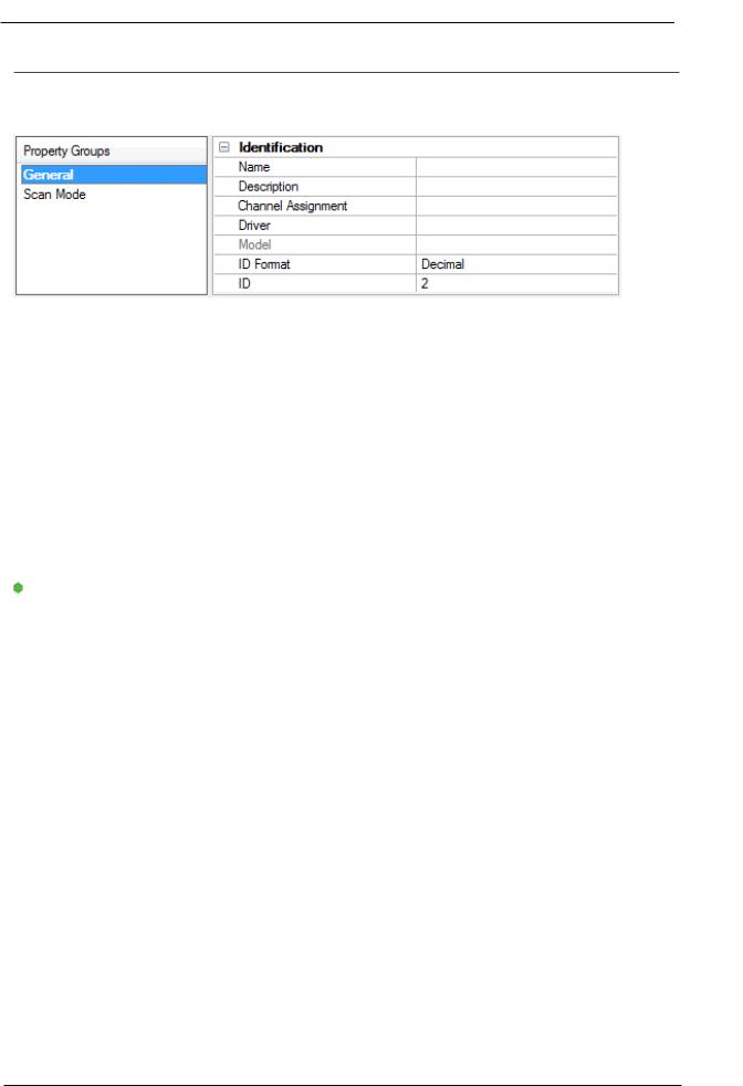
Device Propert ies — General
A device represents a single target on a communications channel. If the driver supports multiple controllers, users must enter a device ID for each controller.
Identification
N am e: Specify the name of the device. It is a logical user-defined name that can be up to 256 characters long and may be used on multiple channels.
 N ote: Although descriptive names are generally a good idea, some OPC client applications may have a limited display window when browsing the OPC server'stag space. The device name and channel name become part of the browse tree information as well. Within an OPC client, the combination of channel name and device name would appear as "ChannelName.DeviceName".
 For more information, refer to "How To... Properly Name a Channel, Device, Tag, and Tag Group" in server help.
Description: Specify the user-defined information about this device.
Many of these properties, including Description, have an associated system tag.
Channel Assignm ent: Specify the user-defined name of the channel to which this device currently belongs.
Driver: Selected protocol driver for this device.
Model: Specify the type of device that is associated with this ID. The contents of the drop-down menu depend on the type of communications driver being used. Models that are not supported by a driver are disabled. If the communications driver supports multiple device models, the model selection can only be changed when there are no client applications connected to the device.
 N ote: If the communication driver supports multiple models, users should try to match the model selection to the physical device. If the device is not represented in the drop-down menu, select a model that conforms closest to the target device. Some drivers support a model selection called "Open," which allows users to communicate without knowing the specific details of the target device. For more information, refer to the driver help documentation.
ID: Specify the device'sdriver-specific station or node. The type of ID entered depends on the communications driver being used. For many communication drivers, the ID is a numeric value. Drivers that support a Numeric ID provide users with the option to enter a numeric value whose format can be changed to suit the needs of the application or the characteristics of the selected communications driver. The format is set by the driver by default. Options include Decimal, Octal, and Hexadecimal.
 N ote: If the driver is Ethernet-based or supports an unconventional station or node name, the device's TCP/IP address may be used as the device ID. TCP/IP addresses consist of four values that are separated by periods, with each value in the range of 0 to 255. Some device IDs are string based. There may be additional
www.ptc.com

13 |
Fanuc Focas Ethernet Driver |
properties to configure within the ID field, depending on the driver. For more information, refer to the driver's help documentation.
Operating M ode
Data Collection: This property controls the device'sactive state. Although device communications are enabled by default, this property can be used to disable a physical device. Communications are not attempted when a device is disabled. From a client standpoint, the data is marked as invalid and write operations are not accepted. This property can be changed at any time through this property or the device system tags.
Sim ulated: Place the device into or out of Simulation Mode. In this mode, the driver does not attempt to communicate with the physical device, but the server continues to return valid OPC data. Simulated stops physical communications with the device, but allows OPC data to be returned to the OPC client as valid data. While in Simulation Mode, the server treats all device data as reflective: whatever is written to the simulated device is read back and each OPC item is treated individually. The item'smemory map is based on the group Update Rate. The data is not saved if the server removes the item (such as when the server is reinitialized). The default is No.
 N otes:
1.This System tag (_Simulated) is read only and cannot be written to for runtime protection. The System tag allows this property to be monitored from the client.
2.In Simulation mode, the item'smemory map is based on client update rate(s) (Group Update Rate for OPC clients or Scan Rate for native and DDE interfaces). This means that two clients that reference the same item with different update rates return different data.
 Simulation Mode is for test and simulation purposes only. It should never be used in a production environment.
Tag Counts
Static Tags: Provides the total number of defined static tags at this level (device or channel). This information can be helpful in troubleshooting and load balancing.
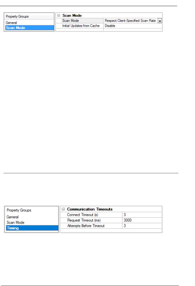
Device Propert ies — Scan M ode
The Scan Mode specifies the subscribed-client requested scan rate for tags that require device communications. Synchronous and asynchronous device reads and writes are processed as soon as possible; unaffected by the Scan Mode properties.
www.ptc.com
Fanuc Focas Ethernet Driver |
14 |
|
Scan Mode: Specify how tags in the device are scanned for updates sent to subscribing clients. Descriptions
of the options are:
•Respect Client-Specified Scan Rate: This mode uses the scan rate requested by the client.
•Request Data N o Faster than Scan Rate: This mode specifies the value set as the maximum scan rate. The valid range is 10 to 99999990 milliseconds. The default is 1000 milliseconds.
 N ote: When the server has an active client and items for the device and the scan rate value is
increased, the changes take effect immediately. When the scan rate value is decreased, the changes
do not take effect until all client applications have been disconnected.
•Request All Data at Scan Rate: This mode forces tags to be scanned at the specified rate for subscribed clients. The valid range is 10 to 99999990 milliseconds. The default is 1000 milliseconds.
•Do N ot Scan, Dem and Poll Only: This mode does not periodically poll tags that belong to the device nor perform a read to get an item'sinitial value once it becomes active. It is the OPC client's responsibility to poll for updates, either by writing to the _DemandPoll tag or by issuing explicit device reads for individual items. For more information, refer to "Device Demand Poll" in server help.
•Respect Tag-Specified Scan Rate: This mode forces static tags to be scanned at the rate specified in their static configuration tag properties. Dynamic tags are scanned at the client-specified scan rate.
Initial Updates from Cache: When enabled, this option allows the server to provide the first updates for newly activated tag references from stored (cached) data. Cache updates can only be provided when the new item reference shares the same address, scan rate, data type, client access, and scaling properties. A device read is used for the initial update for the first client reference only. The default is disabled; any time a client activates a tag reference the server attempts to read the initial value from the device.
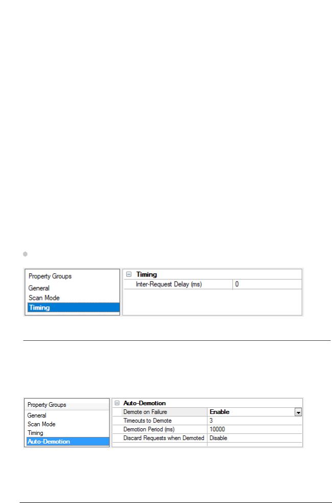
Device Propert ies — Tim ing
The device Timing properties allow the driver'sresponse to error conditions to be tailored to fit the application'sneeds. In many cases, the environment requires changes to these properties for optimum performance. Factors such as electrically generated noise, modem delays, and poor physical connections can influence how many errors or timeouts a communications driver encounters. Timing properties are specific to each configured device.
Communications Timeouts
Connect Tim eout: This property (which is used primarily by Ethernet based drivers) controls the amount of time required to establish a socket connection to a remote device. The device'sconnection time often takes longer than normal communications requests to that same device. The valid range is 1 to 30 seconds. The default is typically 3 seconds, but can vary depending on the driver'sspecific nature. If this setting is not supported by the driver, it is disabled.
www.ptc.com
15 |
Fanuc Focas Ethernet Driver |
 N ote: Due to the nature of UDP connections, the connection timeout setting is not applicable when communicating via UDP.
Request Tim eout: Specify an interval used by all drivers to determine how long the driver waits for a response from the target device to complete. The valid range is 50 to 9,999,999 milliseconds (167.6667 minutes). The default is usually 1000 milliseconds, but can vary depending on the driver. The default timeout for most serial drivers is based on a baud rate of 9600 baud or better. When using a driver at lower baud rates, increase the timeout to compensate for the increased time required to acquire data.
Attem pts Before Tim eout: Specify how many times the driver issues a communications request before considering the request to have failed and the device to be in error. The valid range is 1 to 10. The default is typically 3, but can vary depending on the driver'sspecific nature. The number of attempts configured for an application depends largely on the communications environment. This property applies to both connection attempts and request attempts.
Timing
Inter-Request Delay: Specify how long the driver waits before sending the next request to the target device. It overrides the normal polling frequency of tags associated with the device, as well as one-time reads and writes. This delay can be useful when dealing with devices with slow turnaround times and in cases where network load is a concern. Configuring a delay for a device affects communications with all other devices on the channel. It is recommended that users separate any device that requires an interrequest delay to a separate channel if possible. Other communications properties (such as communication serialization) can extend this delay. The valid range is 0 to 300,000 milliseconds; however, some drivers may limit the maximum value due to a function of their particular design. The default is 0, which indicates no delay between requests with the target device.
N ote: Not all drivers support Inter-Request Delay. This setting does not appear if it is not available.
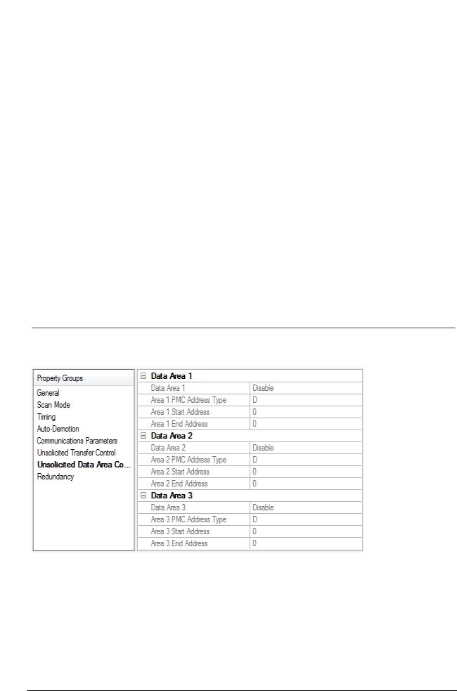
Device Propert ies — Aut o-Dem ot ion
The Auto-Demotion properties can temporarily place a device off-scan in the event that a device is not responding. By placing a non-responsive device offline for a specific time period, the driver can continue to optimize its communications with other devices on the same channel. After the time period has been reached, the driver re-attempts to communicate with the non-responsive device. If the device is responsive, the device is placed on-scan; otherwise, it restarts its off-scan time period.
Dem ote on Failure: When enabled, the device is automatically taken off-scan until it is responding again.  Tip: Determine when a device is off-scan by monitoring its demoted state using the _AutoDemoted system tag.
www.ptc.com

Fanuc Focas Ethernet Driver |
16 |
|
Tim eouts to Dem ote: Specify how many successive cycles of request timeouts and retries occur before the device is placed off-scan. The valid range is 1 to 30 successive failures. The default is 3.
Dem otion Period: Indicate how long the device should be placed off-scan when the timeouts value is reached. During this period, no read requests are sent to the device and all data associated with the read requests are set to bad quality. When this period expires, the driver places the device on-scan and allows for another attempt at communications. The valid range is 100 to 3600000 milliseconds. The default is 10000 milliseconds.
Discard Requests when Dem oted: Select whether or not write requests should be attempted during the off-scan period. Disable to always send write requests regardless of the demotion period. Enable to discard writes; the server automatically fails any write request received from a client and does not post a message to the Event Log.
Device Propert ies — Com m unicat ions Param et ers
TCP/ IP Port: Specify the TCP/IP port number that the remote device is configured to use. The default setting
is 8193.
Maxim um Request Size: Specify the number of bytes that may be requested from a device at one time. To refine the driver'sperformance, configure the request size to one of the following settings: 8, 16, 32, 64, 128, 256, or 512 bytes. The default setting is 256 bytes.
Device Propert ies — Unsolicit ed Transfer Cont rol
Fanuc Focas Server Device: This option should be enabled if the device receives unsolicited data from the CNC. All tags belonging to a Fanuc Focus Server device read data cached in the driver, not directly from the CNC. The Fanuc Focus Server device'stags displays a value of zero until it receives its first unsolicited data update. When disabled, all tags belonging to the device read and write directly to the CNC. The default setting is disabled.
www.ptc.com
17 |
Fanuc Focas Ethernet Driver |
Unsolicited Message Server Port: Specify the port that the unsolicited message server application has been configured to use. The default setting is 8196.
Transfer Control Mem ory Type: Specify the registers'PMC memory type for unsolicited message transfer control. Options include R(internal relay) and E (extended relay). The default setting is R.
Transfer Control Start Address: Specify the start address of the registers used for unsolicited message transfer control. The valid range is 0 to 7999, although the actual range of valid addresses depends on the hardware. The default setting is 0.
Message Retries: Specify the number of times that the CNC should retry sending unsolicited messages. The valid range is 0 to 10. The default setting is 3.
Message Tim eout: Specify the unsolicited message timeout, which is the amount of time that the CNC waits for the driver to respond to an unsolicited message. The valid range is 0 to 30. The default setting is 10 seconds.
Message Alive Tim e: Specify the unsolicited message alive time, which is the amount of time that the CNC retains an unsolicited message for the driver to read. This setting must be less than the message timeout. The valid range is 0 to 30. The default setting is 5 seconds.
 See Also: Unsolicited Messaging
Device Propert ies — Unsolicit ed Dat a Areas
Users can configure up to three areas in PMC memory for unsolicited messaging. These areas'data content is sent to the driver in each unsolicited message. As such, these areas should be made as small as possible.
Data Area n
 N ote: All tags that are created for a Fanuc Focus server device are validated according to the configured data areas. For example, if a Fanuc Focus Server device is configured with a single area with D1000 to D1100, then a tag with address D1000 would be valid, but tags with addresses D1101 or C0001 would be invalid. All tags belonging to a Fanuc Focus Server device are Read Only.
www.ptc.com
Fanuc Focas Ethernet Driver |
18 |
|
•Data Area n: When enabled, this data area is in use.
•PMC Address Type: Specify the area'sPMC address type. The default setting is D. Supported types include the following:
•G: Signal to PMC->CNC
•F: Signal to CNC->PMC
•Y: Signal to PMC->machine
•X: Signal to machine->PMC
•A: Message demand
•R: Internal relay
•T: Changeable timer
•K: Keep relay
•C: Counter
•D: Data table
•Start Address: Specify an area'sstart address. The valid range is 0 and 7999, although the actual range of valid addresses depends on the hardware. The default setting is 0.
•End Address: Specify an area'send address. The valid range is 0 and 7999, although the actual range of valid addresses depends on the hardware. The total number of bytes must not exceed 1430, 1414, or 1398 for areas 1, 2, or 3 respectively. The default value is 0.
 See Also: Unsolicited Messaging
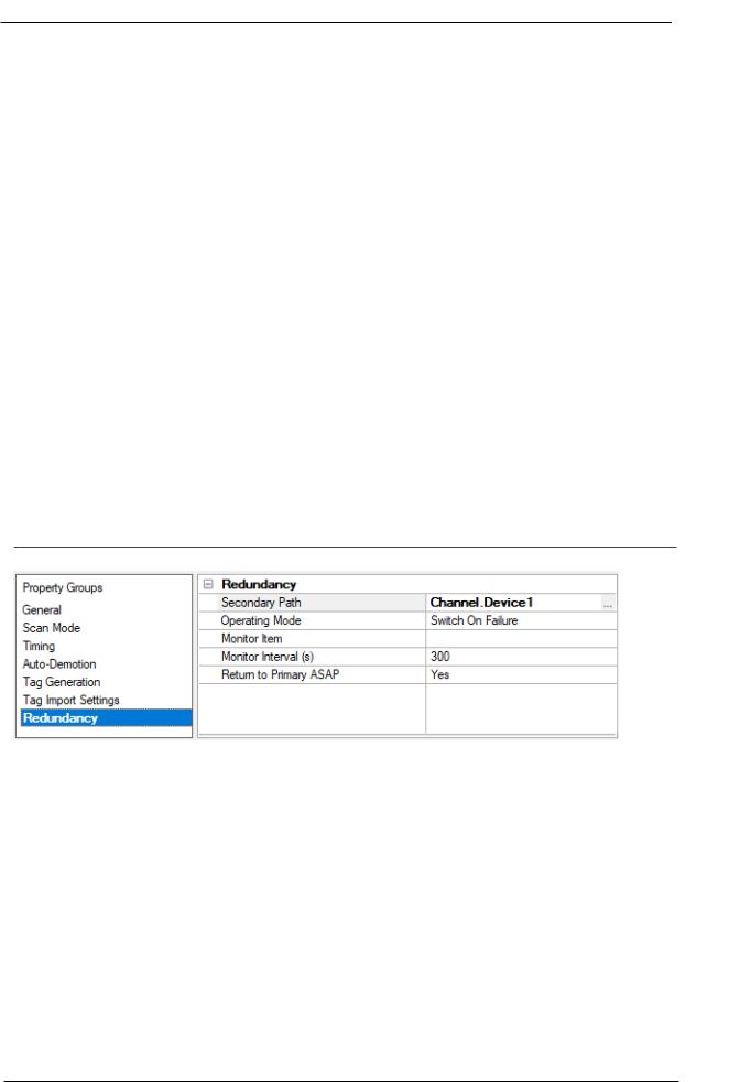
Device Propert ies — Redundancy
Redundancy is available with the Media-Level Redundancy Plug-In.
 Consult the website, a sales representative, or the user manual for more information.
www.ptc.com

19 |
Fanuc Focas Ethernet Driver |
Unsolicit ed M essaging
Before configuring a system for unsolicited messaging, it is important that users understand how the various hardware and software components work together to transfer data. These components include one or more CNC controllers equipped with Fast Ethernet communications boards, firmware that supports unsolicited messaging, and a ladder program. To receive unsolicited data, a host computer must be equipped with the OPC server, its Fanuc Focas Ethernet Driver, the Focas 1 Data Window Library software, and the Unsolicited Message Server. Data can be read from the OPC server with OPC or DDE client applications running on the host or remote computer. For more information, refer to Additional Software Requirem ents.
During an unsolicited messaging session, the controller is only in direct communication with the Unsolicited Message Server. The message server notifies the driver when the controller makes a request to send unsolicited data. The Focas 1 Data Window Library allows the driver to receive the unsolicited data via the message server, and also enables direct communications with the controllers for starting and ending unsolicited messaging sessions.
 N ote: If unsolicited messaging is not used, the driver uses the library to issue read and write requests directly to the controller. It is possible to simultaneously use both types of communication with a controller by creating a Fanuc Focus Server and a non-server device in the OPC server project.
Unsolicited Data Transmission
Ladder programs coordinate the transfer of unsolicited data from their respective controllers and must be tailored to each application. For more information on unsolicited data transmission, refer to the instructions below.
1.To start, the ladder program places the message contents in a designated area of the PMC memory. Once the message is prepared, the ladder controls the data transmission by setting and monitoring bits in the Unsolicited Transfer Control area of PMC memory.
2.To trigger the unsolicited message transmission, the ladder sets the "REQ" (request to send) transfer control bit. The controller sends an "Unsolicited data ready" notification to the message server immediately after.
3.The message server relays the notification to the driver, which then responds by issuing a "Read unsolicited message" command to the message server.
4.The driver receives the unsolicited message data in response to this command, and then replies to the data ready notification with a response code indicating success or failure. The message server then passes this response code to the controller.
5.When the controller receives the response code, it copies it to the "RES_CODE" memory area. The controller sets the "RES" (response ready) bit to indicate that the transaction completed immediately after.
 N ote: The ladder program must be designed to detect when the RES bit has been set. Once it detects that the RES bit has been set, it can read the response code and react as needed. If the data fails to reach the driver, the controller will place its own response code that describes the problem in RES_CODE and set the RES bit.
6.Once the ladder has read the response code, it must clear the REQ bit to ready the system for the next message.
PM C M emory
www.ptc.com
Fanuc Focas Ethernet Driver |
20 |
|
The PMC memory area included in unsolicited messages is defined with the Fanuc Focas Ethernet Driver. The driver transfers these area properties to the controller at the start of an unsolicited messaging session. Data from the range of all areas is included each time an unsolicited message is sent. As such, these areas should be made as small as possible. The ladder program must be written to use the exact address ranges specified in the driver configuration.
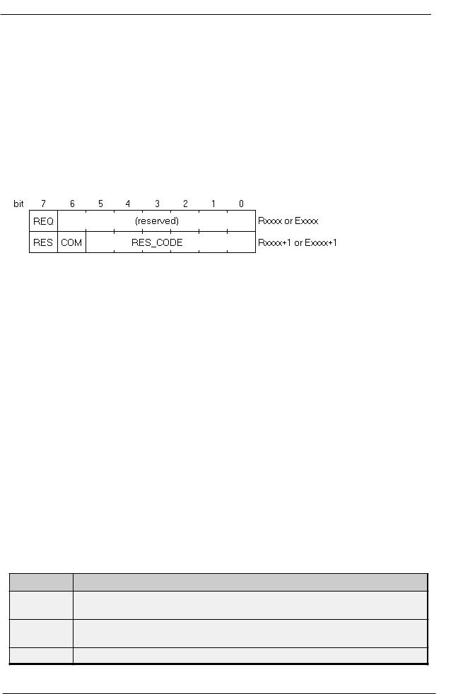
Unsolicited data transmission is coordinated between the ladder program and communications board via 2 bytes of PMC Ror E memory. This transfer control area is defined with the Fanuc Focas Ethernet Driver . The transfer control area properties are then sent to the controller along with the data area properties when an unsolicited messaging session starts. The ladder program must be written to use the specific addresses specified in the driver configuration. The various bits in the transfer control area, with starting address xxxx, have the following locations and meanings:
REQ
Rxxxx.7 (or Exxxx.7)
After the ladder program constructs a message, it must set this bit to 1. This signals the communications board to issue a notification that a new message is ready to be read.
COM
Rxxxx+1.6 (or Exxxx+1.6)
The communications board sets this bit to 1 when message transmission begins. The communications board sets this bit back to 0 immediately before it sets RES to 1, and places the response code in RES_CODE.
RES
Rxxxx+1.7 (or Exxxx+1.7)
The communications board sets this bit to 1 immediately after message transmission completes. When the ladder program detects that this bit is set to 1, it can read the response code from RES_CODE. The ladder then acts depending on the value of RES_CODE. Once this is done, the ladder must set REQ back to 0. This causes the communications board to clear RES_CODE and set the bit back to 0. Then the communications board is ready to perform the next unsolicited transaction.
RES_CODE
Rxxxx+1.0 to Rxxxx+1.5 (or Exxxx+1.0 to Exxxx+1.5)
The result of the unsolicited transaction is placed here. It can be a code passed down from the driver, or a code set by the communications board if there was a communications failure. The possible values are displayed in the table below.
RES_CODE M eaning
Success. The communications board did not detect any failures in communication, and
0x00
the driver reported that it processed the received data successfully.
The transmission control properties are invalid or the unsolicited messaging session
0x01
was not started.
0x02 |
The unsolicited message server is not running. |
www.ptc.com
21 |
Fanuc Focas Ethernet Driver |
RES_CODE |
M eaning |
|
|
|
|
0x03 |
The CNC failed to transmit message. |
|
|
|
|
0x04 |
The CNC failed to receive response. |
|
|
|
|
0x05 |
The transmission retry count was exceeded. |
|
|
|
|
0x06 |
The CNC failed to construct the message data. |
|
|
|
|
0x07 |
The CNC received an invalid packet. |
|
|
|
|
0x08 |
The CNC accepted termination of unsolicited messaging session. |
|
|
|
|
0x10 |
The driver experienced a Focas 1 Library error while reading message. |
|
|
|
|
0x11 |
The driver found the message data to be invalid or experienced other problems while |
|
processing message data. |
||
|
||
|
|
|
0x21 |
The PC application to receive the message does not exist, though the message was |
|
received by the PC. Either the OPC server or this driver is not running. |
||
|
||
|
|
|
|
The PC application to receive the message was not recognized by the unsolicited mes- |
|
0x22 |
sage server, though the message was received by the PC. The unsolicited message |
|
server may need be restarted, or there may have been a problem when the driver was |
||
|
||
|
starting the unsolicited messaging session. |
|
|
|
|
0x23 |
The CNC failed in writing the received message to the PC. |
|
|
|
|
0x24 |
The timeout period and retry count have expired. |
|
|
|
|
0x25 |
Illegal data was included in the received message. |
|
|
|
The Fanuc Focas Ethernet Driver stores unsolicited data in a memory cache. The OPC server makes this data visible to client applications via tags, whose addresses must be the same as the controller'sdata source. For example, if an unsolicited data area is configured to include the byte at D1000, then a tag with an address of D1000 must be used to view the data. These tags show the last values sent to the driver, which may not necessarily be the current values in the controller. To poll current values directly from the controller, users would need additional tags belonging to a non-server device. Fanuc Focus Server device tags display a value of zero until the driver receives its first unsolicited data update from the controller.
 N otes:
1.In addition to data ready notifications, the Unsolicited Message Server also apprises the driver of other important events. These include CNC power up, CNC power down, Unsolicited Message Server shutdown, and communications error notifications. The driver responds to each of these events in such a way that communication with the hardware is maintained, if possible.
2.The device's_System._Error Tag is set if the driver fails to start an unsolicited messaging session, or restarts the session after detecting a communications problem. Tags that belong to a Fanuc Focus Server device in an error state will continue to display the last value received from the device or the initial value of zero.
www.ptc.com
Fanuc Focas Ethernet Driver |
22 |
|
Opt im izing Com m unicat ions
The Fanuc Focas Ethernet Driver has been designed to provide the best performance with the least amount of impact on the system'soverall performance. While the driver is fast, there are a couple of guidelines that can be used to control and optimize the application and gain maximum performance.
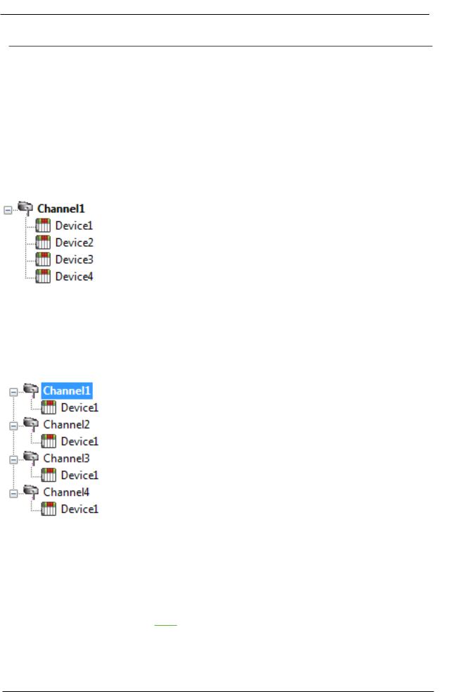
This server refers to communications protocols like Fanuc Focas Ethernet as a channel. Each channel defined in the application represents a separate path of execution in the server. Once a channel has been defined, a series of devices must then be defined under that channel. Each of these devices represents a single Fanuc Focas controller from which data is collected. While this approach to defining the application provides a high level of performance, it won'take full advantage of the Fanuc Focas Ethernet Driver or the network. An example of how the application may appear when configured using a single channel is shown below.
Each device appears under a single channel. In this configuration, the driver must move from one device to the next as quickly as possible to gather information at an effective rate. As more devices are added or more information is requested from a single device, the overall update rate begins to suffer.
If the Fanuc Focas Ethernet Driver could only define one single channel, then the example shown above would be the only option available; however, the driver can define up to 256 channels. Using multiple channels distributes the data collection workload by simultaneously issuing multiple requests to the network. An example of how the same application may appear when configured using multiple channels to improve performance is shown below.
Each device can be defined under its own channel. In this configuration, a single path of execution is dedicated to the task of gathering data from each device. If the application has fewer devices, it can be optimized exactly how it is shown here.
There is performance improvement even if the application has more devices.
While fewer devices may be ideal, the application still benefits from additional channels. Although spreading the device load across all channels causes the server to move from device to device again, it can now do so with far less devices to process on a single channel.
Request Size can also affect the Fanuc Focas Ethernet Driver performance. The request size refers to the number of bytes that may be requested from a device at one time and is available on every defined device. To refine the driver'sperformance, configure the request size to one of the following settings: 8, 16, 32, 64, 128, 256, or 512 bytes. Depending on the model of the device being used, the setting chosen for request size can dramatically affect the application. The default value of 256 bytes is recommended. If the application consists of large requests for consecutively ordered data, try increasing the request size setting for the device. For more information, refer to Setup.
www.ptc.com

23 |
|
|
Fanuc Focas Ethernet Driver |
|
|
|
Dat a Types Descript ion |
||
|
|
|
|
|
|
|
Dat a Type |
Descript ion |
|
|
|
|
|
|
|
|
Boolean |
Single bit |
|
|
|
|
|
|
|
|
|
Unsigned 8-bit value |
|
|
|
Byte |
|
|
|
|
|
bit 0 is the low bit |
|
|
|
|
bit 7 is the high bit |
|
|
|
|
|
|
|
|
|
Unsigned 16-bit value |
|
|
|
Word |
bit 0 is the low bit |
|
|
|
|
|
|
|
|
|
bit 15 is the high bit |
|
|
|
|
|
|
|
|
|
Signed 16-bit value |
|
|
|
Short |
bit 0 is the low bit |
|
|
|
|
bit 14 is the high bit |
|
|
|
|
bit 15 is the sign bit |
|
|
|
|
|
|
|
|
|
Unsigned 32-bit value |
|
|
|
DWord |
bit 0 is the low bit |
|
|
|
|
|
|
|
|
|
bit 31 is the high bit |
|
|
|
|
|
|
|
|
|
Signed 32-bit value |
|
|
|
Long |
bit 0 is the low bit |
|
|
|
|
bit 30 is the high bit |
|
|
|
|
bit 31 is the sign bit |
|
|
|
|
|
|
|
|
Float |
32-bit floating point value |
|
|
|
|
|
|
|
|
String |
Null terminated ASCII string |
|
|
|
|
|
|
www.ptc.com

Fanuc Focas Ethernet Driver |
24 |
|
Address Descript ions
Address specifications may vary depending on the model in use. Select a link from the following list to obtain specific address information for the model of interest.
 N ote: If the model of interest is listed as supported but is not selectable, use the Open model.
Series 15i
Series 16i
Series 18i
Series 21i
Power M at e i
Open
Series 15i
The following addresses are supported for this model. Not all address ranges may be valid for the particular device being used. For more information, refer to the specific device'sdocumentation. To jump to a specific section, select a link from the list below.
CN C Dat a
Arrays
St rings
PM C Data
The default data types for dynamically defined DDE tags are shown in bold.
Address Type |
Range |
Dat a Type |
Access |
|
|
|
|
|
|
|
A00000-A00124 |
Byte, Char |
|
|
A (Message demand) |
A00000-A00123 |
Word, Short |
Read/Write |
|
A00000-A00121 |
DWord, Long, Float |
|||
|
|
|||
|
Axxxxx.0-Axxxxx.7 |
Boolean |
|
|
|
|
|
|
|
|
C00000-C00199 |
Byte, Char |
|
|
C (Counter) |
C00000-C00198 |
Word, Short |
Read/Write |
|
C00000-C00196 |
DWord, Long, Float |
|||
|
|
|||
|
Cxxxxx.0-Cxxxxx.7 |
Boolean |
|
|
|
|
|
|
|
|
D00000-D09999 |
Byte, Char |
|
|
D (Data table) |
D00000-D09998 |
Word, Short |
Read/Write |
|
D00000-D09996 |
DWord, Long, Float |
|||
|
|
|||
|
Dxxxxx.0-Dxxxxx.7 |
Boolean |
|
|
|
|
|
|
|
|
F00000-F00511 |
Byte, Char |
|
|
F (Signal to CNC->PMC) |
F00000-F00510 |
Word, Short |
Read Only |
|
F00000-F00508 |
DWord, Long, Float |
|||
|
|
|||
|
Fxxxxx.0-Fxxxxx.7 |
Boolean |
|
|
|
|
|
|
|
|
G00000-G00511 |
Byte, Char |
|
|
G (Signal to PMC->CNC) |
G00000-G00510 |
Word, Short |
Read/Write |
|
G00000-G00508 |
DWord, Long, Float |
|||
|
|
|||
|
Gxxxxx.0-Gxxxxx.7 |
Boolean |
|
|
|
|
|
|
www.ptc.com
Loading...