


 Loading...
FANUC Series 16/18 /160/180 – Model PB
Descriptions Manual
B-62622EN/02

•No part of this manual may be reproduced in any form.
•All specifications and designs are subject to change without notice.
The export of this product is subject to the authorization of the government of the country from where the product is exported.
In this manual we have tried as much as possible to describe all the various matters. However, we cannot describe all the matters which must not be done, or which cannot be done, because there are so many possibilities.
Therefore, matters which are not especially described as possible in this manual should be regarded as ”impossible”.
This manual contains the program names or device names of other companies, some of which are registered trademarks of respective owners. However, these names are not followed by or in the main body.

B±62622EN/02 |
Table of Contents |
|
I. GENERAL |
|
|
1. |
GENERAL . . . . . . . . . . . . . . . . . . . . . . . . . |
. . . . . . . . . . . . . . . . . . . . . . . . . . . . . . . . . . . . . 3 |
2. |
LIST OF SPECIFICATIONS . . . . . . . . . . |
. . . . . . . . . . . . . . . . . . . . . . . . . . . . . . . . . . . . . 5 |
II. NC FUNCTION
1. |
CONTROLLED AXES . . . . . . . . . . . . . . . . . . . . . . . . . . . . . . . . . . . . . . . . . . . . . . . . . . . . |
15 |
||
|
1.1 |
NUMBER OF THE ALL CONTROLLED AXES . . . . . . . . . . . . . . . . . . . . . . . . . . . . . . . . . . . . . |
15 |
|
|
1.2 |
MACHINE CONTROLLED AXES . . . . . . . . . . . . . . . . . . . . . . . . . . . . . . . . . . . . . . . . . . . . . . . . |
15 |
|
|
|
1.2.1 |
Number of Basic Controlled Axes . . . . . . . . . . . . . . . . . . . . . . . . . . . . . . . . . . . . . . . . . . . . . . . . . . . . |
15 |
|
|
1.2.2 |
Number of Basic Simultaneously Controlled Axes . . . . . . . . . . . . . . . . . . . . . . . . . . . . . . . . . . . . . . . . |
15 |
|
|
1.2.3 |
Number of Controlled Axes Expanded (All) . . . . . . . . . . . . . . . . . . . . . . . . . . . . . . . . . . . . . . . . . . . . |
15 |
|
|
1.2.4 |
Number of Simultaneously Controlled Axes Expanded (All) . . . . . . . . . . . . . . . . . . . . . . . . . . . . . . . . |
15 |
|
|
1.2.5 |
Axis Control by PMC . . . . . . . . . . . . . . . . . . . . . . . . . . . . . . . . . . . . . . . . . . . . . . . . . . . . . . . . . . . . . . |
15 |
|
1.3 |
AXIS NAMES . . . . . . . . . . . . . . . . . . . . . . . . . . . . . . . . . . . . . . . . . . . . . . . . . . . . . . . . . . . . . . . . . |
16 |
|
|
1.4 |
INCREMENT SYSTEM . . . . . . . . . . . . . . . . . . . . . . . . . . . . . . . . . . . . . . . . . . . . . . . . . . . . . . . . . |
17 |
|
|
|
1.4.1 |
Input Unit (10 Times) . . . . . . . . . . . . . . . . . . . . . . . . . . . . . . . . . . . . . . . . . . . . . . . . . . . . . . . . . . . . . . |
18 |
|
1.5 |
MAXIMUM STROKE . . . . . . . . . . . . . . . . . . . . . . . . . . . . . . . . . . . . . . . . . . . . . . . . . . . . . . . . . . |
19 |
|
2. |
PREPARATORY FUNCTIONS . . . . . . . . . . . . . . . . . . . . . . . . . . . . . . . . . . . . . . . . . . . . |
20 |
||
3. |
INTERPOLATION FUNCTIONS . . . . . . . . . . . . . . . . . . . . . . . . . . . . . . . . . . . . . . . . . . . |
22 |
||
|
3.1 |
POSITIONING (G00) . . . . . . . . . . . . . . . . . . . . . . . . . . . . . . . . . . . . . . . . . . . . . . . . . . . . . . . . . . . |
23 |
|
|
3.2 |
LINEAR INTERPOLATION (G01) . . . . . . . . . . . . . . . . . . . . . . . . . . . . . . . . . . . . . . . . . . . . . . . . |
24 |
|
|
3.3 |
CIRCULAR INTERPOLATION (G02, G03) . . . . . . . . . . . . . . . . . . . . . . . . . . . . . . . . . . . . . . . . . |
25 |
|
4. |
FEED FUNCTIONS . . . . . . . . . . . . . . . . . . . . . . . . . . . . . . . . . . . . . . . . . . . . . . . . . . . . . . |
26 |
||
|
4.1 |
RAPID TRAVERSE . . . . . . . . . . . . . . . . . . . . . . . . . . . . . . . . . . . . . . . . . . . . . . . . . . . . . . . . . . . . |
27 |
|
|
4.2 |
CUTTING FEED RATE . . . . . . . . . . . . . . . . . . . . . . . . . . . . . . . . . . . . . . . . . . . . . . . . . . . . . . . . . |
28 |
|
|
|
4.2.1 |
Tangential Speed Constant Control . . . . . . . . . . . . . . . . . . . . . . . . . . . . . . . . . . . . . . . . . . . . . . . . . . . . |
28 |
|
|
4.2.2 |
Cutting Feed Rate Clamp . . . . . . . . . . . . . . . . . . . . . . . . . . . . . . . . . . . . . . . . . . . . . . . . . . . . . . . . . . . |
28 |
|
|
4.2.3 |
Per Minute Feed (G94) . . . . . . . . . . . . . . . . . . . . . . . . . . . . . . . . . . . . . . . . . . . . . . . . . . . . . . . . . . . . . |
28 |
|
4.3 |
OVERRIDE . . . . . . . . . . . . . . . . . . . . . . . . . . . . . . . . . . . . . . . . . . . . . . . . . . . . . . . . . . . . . . . . . . . |
29 |
|
|
|
4.3.1 |
Feed Rate Override . . . . . . . . . . . . . . . . . . . . . . . . . . . . . . . . . . . . . . . . . . . . . . . . . . . . . . . . . . . . . . . . |
29 |
|
|
4.3.2 |
Second Feed Rate Override . . . . . . . . . . . . . . . . . . . . . . . . . . . . . . . . . . . . . . . . . . . . . . . . . . . . . . . . . . |
29 |
|
|
4.3.3 |
Rapid Traverse Override . . . . . . . . . . . . . . . . . . . . . . . . . . . . . . . . . . . . . . . . . . . . . . . . . . . . . . . . . . . . |
29 |
|
|
4.3.4 |
Override Cancel . . . . . . . . . . . . . . . . . . . . . . . . . . . . . . . . . . . . . . . . . . . . . . . . . . . . . . . . . . . . . . . . . . . |
29 |
|
|
4.3.5 |
Jog Override . . . . . . . . . . . . . . . . . . . . . . . . . . . . . . . . . . . . . . . . . . . . . . . . . . . . . . . . . . . . . . . . . . . . . |
29 |
|
|
4.3.6 |
F1-digit (Programmable Rapid Traverse Override) . . . . . . . . . . . . . . . . . . . . . . . . . . . . . . . . . . . . . . . |
29 |
|
4.4 |
AUTOMATIC ACCELERATION/ DECELERATION . . . . . . . . . . . . . . . . . . . . . . . . . . . . . . . . . . |
30 |
|
4.4.1Switching Rapid Traverse Feedrates, Time Constants, and/or Servo Loop Gains According to
|
the Positioning Distance . . . . . . . . . . . . . . . . . . . . . . . . . . . . . . . . . . . . . . . . . . . . . . . . . . . . . . . . . . . . |
31 |
4.4.2 |
Constant-positioning- time Control . . . . . . . . . . . . . . . . . . . . . . . . . . . . . . . . . . . . . . . . . . . . . . . . . . . . |
31 |
4.5 |
LINEAR ACCELERATION/ DECELERATION AFTER CUTTING FEED INTERPOLATION |
32 |

Table of Contents |
B±62622EN/02 |
|
|
4.6LINEAR ACCELERATION/ DECELERATION BEFORE CUTTING FEED
|
|
INTERPOLATION . . . . . . . . . . . . . . . . . . . . . . . . . . . . . . . . . . . . . . . . . . . . . . . . . . . . . . . . . . . . . |
33 |
|
|
4.7 |
ERROR DETECTION . . . . . . . . . . . . . . . . . . . . . . . . . . . . . . . . . . . . . . . . . . . . . . . . . . . . . . . . . . . |
34 |
|
|
4.8 |
EXACT STOP (G09) . . . . . . . . . . . . . . . . . . . . . . . . . . . . . . . . . . . . . . . . . . . . . . . . . . . . . . . . . . . . |
35 |
|
|
4.9 |
EXACT STOP MODE (G61) . . . . . . . . . . . . . . . . . . . . . . . . . . . . . . . . . . . . . . . . . . . . . . . . . . . . . |
35 |
|
|
4.10 |
CUTTING MODE (G64) . . . . . . . . . . . . . . . . . . . . . . . . . . . . . . . . . . . . . . . . . . . . . . . . . . . . . . . . . |
35 |
|
|
4.11 |
AUTOMATIC CORNER OVERRIDE (G62) . . . . . . . . . . . . . . . . . . . . . . . . . . . . . . . . . . . . . . . . . |
35 |
|
|
4.12 |
DWELL (G04) . . . . . . . . . . . . . . . . . . . . . . . . . . . . . . . . . . . . . . . . . . . . . . . . . . . . . . . . . . . . . . . . . |
35 |
|
5. |
REFERENCE POSITION . . . . . . . . . . . . . . . . . . . . . . . . . . . . . . . . . . . . . . . . . . . . . . . . . |
36 |
||
|
5.1 |
MANUAL REFERENCE POSITION RETURN . . . . . . . . . . . . . . . . . . . . . . . . . . . . . . . . . . . . . . |
37 |
|
|
5.1.1 |
Manual Reference Position Return . . . . . . . . . . . . . . . . . . . . . . . . . . . . . . . . . . . . . . . . . . . . . . . . . . . . |
37 |
|
|
5.1.2 |
Setting the Reference Position without Dogs . . . . . . . . . . . . . . . . . . . . . . . . . . . . . . . . . . . . . . . . . . . . |
37 |
|
|
5.2 |
AUTOMATIC REFERENCE POSITION RETURN . . . . . . . . . . . . . . . . . . . . . . . . . . . . . . . . . . . |
38 |
|
6. |
COORDINATE SYSTEMS . . . . . . . . . . . . . . . . . . . . . . . . . . . . . . . . . . . . . . . . . . . . . . . . |
39 |
||
|
6.1 |
MACHINE COORDINATE SYSTEM (G53) . . . . . . . . . . . . . . . . . . . . . . . . . . . . . . . . . . . . . . . . . |
40 |
|
|
6.2 |
WORKPIECE COORDINATE SYSTEM . . . . . . . . . . . . . . . . . . . . . . . . . . . . . . . . . . . . . . . . . . . . |
41 |
|
|
6.2.1 |
Setting a Workpiece Coordinate System (Using G92) . . . . . . . . . . . . . . . . . . . . . . . . . . . . . . . . . . . . . |
41 |
|
|
6.2.2 |
Automatic Coordinate System Setting . . . . . . . . . . . . . . . . . . . . . . . . . . . . . . . . . . . . . . . . . . . . . . . . . |
42 |
|
|
6.2.3 |
Setting a Workpiece Coordinate System (Using G54 to G59) . . . . . . . . . . . . . . . . . . . . . . . . . . . . . . . |
42 |
|
|
6.3 |
LOCAL COORDINATE SYSTEM SYSTEM (G52) . . . . . . . . . . . . . . . . . . . . . . . . . . . . . . . . . . . |
43 |
|
6.4WORKPIECE ORIGIN OFFSET VALUE CHANGE
(PROGRAMMABLE DATA INPUT) (G10) . . . . . . . . . . . . . . . . . . . . . . . . . . . . . . . . . . . . . . . . . |
44 |
6.5 PLANE SELECTION (G17, G18, G19) . . . . . . . . . . . . . . . . . . . . . . . . . . . . . . . . . . . . . . . . . . . . . |
45 |
7. COORDINATE VALUE AND DIMENSION . . . . . . . . . . . . . . . . . . . . . . . . . . . . . . . . . . |
46 |
|
7.1 |
ABSOLUTE AND INCREMENTAL PROGRAMMING (G90, G91) . . . . . . . . . . . . . . . . . . . . . . |
47 |
7.2 |
INCH/METRIC CONVERSION (G20, G21) . . . . . . . . . . . . . . . . . . . . . . . . . . . . . . . . . . . . . . . . . |
48 |
7.3 |
DECIMAL POINT INPUT/POCKET CALCULATOR TYPE DECIMAL POINT INPUT . . . . . |
48 |
7.4 |
LINEAR AXIS AND ROTATION AXIS . . . . . . . . . . . . . . . . . . . . . . . . . . . . . . . . . . . . . . . . . . . . |
48 |
7.5 |
ROTATION AXIS ROLL-OVER FUNCTION . . . . . . . . . . . . . . . . . . . . . . . . . . . . . . . . . . . . . . . . |
48 |
8. |
PRESS FUNCTIONS . . . . . . . . . . . . . . . . . . . . . . . . . . . . . . . . . . . . . . . . . . . . . . . . . . . . |
49 |
|
|
8.1 |
ONE-CYCLE PRESS . . . . . . . . . . . . . . . . . . . . . . . . . . . . . . . . . . . . . . . . . . . . . . . . . . . . . . . . . . . |
50 |
|
8.2 |
CONTINUOUS PRESS (NIBBLING) . . . . . . . . . . . . . . . . . . . . . . . . . . . . . . . . . . . . . . . . . . . . . . |
51 |
|
|
8.2.1 Circular Nibbling (G68) And Linear Nibbling (G69) . . . . . . . . . . . . . . . . . . . . . . . . . . . . . . . . . . . . . . |
51 |
|
|
8.2.2 Nibbling Mode (M-code) . . . . . . . . . . . . . . . . . . . . . . . . . . . . . . . . . . . . . . . . . . . . . . . . . . . . . . . . . . . |
52 |
|
8.3 |
MANUAL PRESS . . . . . . . . . . . . . . . . . . . . . . . . . . . . . . . . . . . . . . . . . . . . . . . . . . . . . . . . . . . . . . |
54 |
|
8.4 |
POSITIONING AND NO PRESS START SIGNAL (G70) . . . . . . . . . . . . . . . . . . . . . . . . . . . . . . |
54 |
|
8.5 |
SETTING UP PRESS START SIGNAL OUTPUT CONDITIONS . . . . . . . . . . . . . . . . . . . . . . . . |
54 |
|
8.6 |
PRESS ACTIVATION LOCK . . . . . . . . . . . . . . . . . . . . . . . . . . . . . . . . . . . . . . . . . . . . . . . . . . . . . |
54 |
|
8.7 |
DEFERRING PRESS ACTIVATION . . . . . . . . . . . . . . . . . . . . . . . . . . . . . . . . . . . . . . . . . . . . . . . |
54 |
|
8.8 |
SWITCHING BETWEEN TWO NIBBLING PITCHES . . . . . . . . . . . . . . . . . . . . . . . . . . . . . . . . |
54 |
|
8.9 |
EXTERNAL OPERATION FUNCTION . . . . . . . . . . . . . . . . . . . . . . . . . . . . . . . . . . . . . . . . . . . . |
54 |
9. |
SPINDLE FUNCTIONS . . . . . . . . . . . . . . . . . . . . . . . . . . . . . . . . . . . . . . . . . . . . . . . . . . . |
55 |
|
9.1 S CODE OUTPUT . . . . . . . . . . . . . . . . . . . . . . . . . . . . . . . . . . . . . . . . . . . . . . . . . . . . . . . . . . . . . . |
56 |

B±62622EN/02 |
|
Table of Contents |
|
|
|
|
|
9.2 |
SPINDLE SPEED COMMAND CONTROL BY THE PMC . . . . . . . . . . . . . . . . . . . . . . . . . . . . . |
56 |
|
10. TOOL FUNCTIONS . . . . . . . . . . . . . . . . . . . . . . . . . . . . . . . . . . . . . . . . . . . . . . . . . . . . . . |
57 |
||
10.1 |
T CODE OUTPUT . . . . . . . . . . . . . . . . . . . . . . . . . . . . . . . . . . . . . . . . . . . . . . . . . . . . . . . . . . . . . . |
58 |
|
10.2 |
T-AXIS CONTROL . . . . . . . . . . . . . . . . . . . . . . . . . . . . . . . . . . . . . . . . . . . . . . . . . . . . . . . . . . . . . |
58 |
|
10.3 |
IGNORING T-CODE . . . . . . . . . . . . . . . . . . . . . . . . . . . . . . . . . . . . . . . . . . . . . . . . . . . . . . . . . . . . |
58 |
|
10.4 |
MULTIPLE TOOL CONTROL . . . . . . . . . . . . . . . . . . . . . . . . . . . . . . . . . . . . . . . . . . . . . . . . . . . . |
59 |
|
10.4.1 |
Tool Number . . . . . . . . . . . . . . . . . . . . . . . . . . . . . . . . . . . . . . . . . . . . . . . . . . . . . . . . . . . . . . . . . . . . . |
59 |
|
10.4.2 Relationship Between the Multiple-tool System and the C Axis . . . . . . . . . . . . . . . . . . . . . . . . . . . . . |
60 |
||
10.4.3 |
Tool Compensation . . . . . . . . . . . . . . . . . . . . . . . . . . . . . . . . . . . . . . . . . . . . . . . . . . . . . . . . . . . . . . . . |
61 |
|
10.5 |
TOOL LIFE MANAGEMENT . . . . . . . . . . . . . . . . . . . . . . . . . . . . . . . . . . . . . . . . . . . . . . . . . . . . |
62 |
|
11. MISCELLANEOUS FUNCTIONS . . . . . . . . . . . . . . . . . . . . . . . . . . . . . . . . . . . . . . . . . . |
63 |
||
11.1 |
MISCELLANEOUS FUNCTIONS . . . . . . . . . . . . . . . . . . . . . . . . . . . . . . . . . . . . . . . . . . . . . . . . . |
64 |
|
11.2 |
1-BLOCK PLURAL M COMMAND . . . . . . . . . . . . . . . . . . . . . . . . . . . . . . . . . . . . . . . . . . . . . . . |
65 |
|
11.3 |
SECOND MISCELLANEOUS FUNCTIONS . . . . . . . . . . . . . . . . . . . . . . . . . . . . . . . . . . . . . . . . |
65 |
|
11.4 |
HIGH-SPEED M/S/T/B INTERFACE . . . . . . . . . . . . . . . . . . . . . . . . . . . . . . . . . . . . . . . . . . . . . . |
66 |
|
12. PROGRAM CONFIGURATION . . . . . . . . . . . . . . . . . . . . . . . . . . . . . . . . . . . . . . . . . . . . |
68 |
||
12.1 |
PROGRAM NUMBER . . . . . . . . . . . . . . . . . . . . . . . . . . . . . . . . . . . . . . . . . . . . . . . . . . . . . . . . . . |
69 |
|
12.2 |
PROGRAM NAME . . . . . . . . . . . . . . . . . . . . . . . . . . . . . . . . . . . . . . . . . . . . . . . . . . . . . . . . . . . . . |
69 |
|
12.3 |
MAIN PROGRAM . . . . . . . . . . . . . . . . . . . . . . . . . . . . . . . . . . . . . . . . . . . . . . . . . . . . . . . . . . . . . |
69 |
|
12.4 |
SUB PROGRAM . . . . . . . . . . . . . . . . . . . . . . . . . . . . . . . . . . . . . . . . . . . . . . . . . . . . . . . . . . . . . . . |
70 |
|
12.5 |
EXTERNAL MEMORY AND SUB PROGRAM CALLING FUNCTION . . . . . . . . . . . . . . . . . . |
71 |
|
12.6 |
SEQUENCE NUMBER . . . . . . . . . . . . . . . . . . . . . . . . . . . . . . . . . . . . . . . . . . . . . . . . . . . . . . . . . . |
71 |
|
12.7 |
TAPE CODES . . . . . . . . . . . . . . . . . . . . . . . . . . . . . . . . . . . . . . . . . . . . . . . . . . . . . . . . . . . . . . . . . |
71 |
|
12.8 |
BASIC ADDRESSES AND COMMAND VALUE RANGE . . . . . . . . . . . . . . . . . . . . . . . . . . . . . |
72 |
|
12.9 |
TAPE FORMAT . . . . . . . . . . . . . . . . . . . . . . . . . . . . . . . . . . . . . . . . . . . . . . . . . . . . . . . . . . . . . . . . |
73 |
|
12.10 |
LABEL SKIP . . . . . . . . . . . . . . . . . . . . . . . . . . . . . . . . . . . . . . . . . . . . . . . . . . . . . . . . . . . . . . . . . . |
73 |
|
12.11 |
CONTROL-IN/ CONTROL-OUT . . . . . . . . . . . . . . . . . . . . . . . . . . . . . . . . . . . . . . . . . . . . . . . . . . |
73 |
|
12.12 |
OPTIONAL BLOCK SKIP . . . . . . . . . . . . . . . . . . . . . . . . . . . . . . . . . . . . . . . . . . . . . . . . . . . . . . . |
73 |
|
12.13 |
ADDITIONAL OPTIONAL BLOCK SKIP . . . . . . . . . . . . . . . . . . . . . . . . . . . . . . . . . . . . . . . . . . |
73 |
|
12.14TAPE HORIZONTAL (TH) PARITY CHECK AND
TAPE VERTICAL (TV) PARITY CHECK . . . . . . . . . . . . . . . . . . . . . . . . . . . . . . . . . . . . . . . . . . . |
73 |
13. FUNCTION TO SIMPLIFY PROGRAMMING . . . . . . . . . . . . . . . . . . . . . . . . . . . . . . . . |
74 |
||
13.1 |
PATTERN FUNCTION . . . . . . . . . . . . . . . . . . . . . . . . . . . . . . . . . . . . . . . . . . . . . . . . . . . . . . . . . . |
75 |
|
13.1.1 Bolt Hole Circle (G26) . . . . . . . . . . . . . . . . . . . . . . . . . . . . . . . . . . . . . . . . . . . . . . . . . . . . . . . . . . . . . |
75 |
||
13.1.2 Line at Angle (G76) . . . . . . . . . . . . . . . . . . . . . . . . . . . . . . . . . . . . . . . . . . . . . . . . . . . . . . . . . . . . . . . |
75 |
||
13.1.3 |
Arc (G77) . . . . . . . . . . . . . . . . . . . . . . . . . . . . . . . . . . . . . . . . . . . . . . . . . . . . . . . . . . . . . . . . . . . . . . . |
76 |
|
13.1.4 |
Grid (G78, G79) . . . . . . . . . . . . . . . . . . . . . . . . . . . . . . . . . . . . . . . . . . . . . . . . . . . . . . . . . . . . . . . . . . |
76 |
|
13.1.5 |
Share Proof (G86) . . . . . . . . . . . . . . . . . . . . . . . . . . . . . . . . . . . . . . . . . . . . . . . . . . . . . . . . . . . . . . . . . |
77 |
|
13.1.6 |
Square (G87) . . . . . . . . . . . . . . . . . . . . . . . . . . . . . . . . . . . . . . . . . . . . . . . . . . . . . . . . . . . . . . . . . . . . . |
77 |
|
13.1.7 |
Radius (G88) . . . . . . . . . . . . . . . . . . . . . . . . . . . . . . . . . . . . . . . . . . . . . . . . . . . . . . . . . . . . . . . . . . . . . |
78 |
|
13.1.8 Cut at Angle (G89) . . . . . . . . . . . . . . . . . . . . . . . . . . . . . . . . . . . . . . . . . . . . . . . . . . . . . . . . . . . . . . . . |
78 |
||
13.2 |
BASE POINT COMMAND (G72) . . . . . . . . . . . . . . . . . . . . . . . . . . . . . . . . . . . . . . . . . . . . . . . . . |
79 |
|
13.3 |
STORAGE AND CALL BY ADDRESS A/B . . . . . . . . . . . . . . . . . . . . . . . . . . . . . . . . . . . . . . . . . |
80 |
|
13.4 |
AUTOMATIC REPOSITIONING (G75) . . . . . . . . . . . . . . . . . . . . . . . . . . . . . . . . . . . . . . . . . . . . |
81 |
|

|
Table of Contents |
B±62622EN/02 |
|
13.5 |
U/V/W MACRO FUNCTION . . . . . . . . . . . . . . . . . . . . . . . . . . . . . . . . . . . . . . . . . . . . . . . |
. . . . . . |
82 |
13.5.1 Storage of Macro (U, V Command) . . . . . . . . . . . . . . . . . . . . . . . . . . . . . . . . . . . . . . . . . . . . . |
. . . . . . |
82 |
|
13.5.2 Macro Call (W Command) . . . . . . . . . . . . . . . . . . . . . . . . . . . . . . . . . . . . . . . . . . . . . . . . . . . . . |
. . . . . |
83 |
|
13.5.3 Multiple Call of Macro . . . . . . . . . . . . . . . . . . . . . . . . . . . . . . . . . . . . . . . . . . . . . . . . . . . . . . . . |
. . . . . |
83 |
|
13.5.4 Storage Capacity of Macro . . . . . . . . . . . . . . . . . . . . . . . . . . . . . . . . . . . . . . . . . . . . . . . . . . . . . |
. . . . . |
83 |
|
13.5.5 Storage and Call of Plural Macro (Macro No.90 to 99) . . . . . . . . . . . . . . . . . . . . . . . . . . . . . . . |
. . . . . |
83 |
|
13.6 |
MULTIPLE-PIECE MACHINING . . . . . . . . . . . . . . . . . . . . . . . . . . . . . . . . . . . . . . . . . . . . |
. . . . . |
84 |
13.6.1 Base Point Command of Multi-piece Machining . . . . . . . . . . . . . . . . . . . . . . . . . . . . . . . . . . . . |
. . . . . |
85 |
|
13.6.2 Multi-piecemachining Command . . . . . . . . . . . . . . . . . . . . . . . . . . . . . . . . . . . . . . . . . . . . . . . . |
. . . . . |
86 |
|
13.6.3 Setting of Processing Method of Multi-piece Machining . . . . . . . . . . . . . . . . . . . . . . . . . . . . . . |
. . . . . |
86 |
|
13.6.4 Command to Restart Punching Multiple Products . . . . . . . . . . . . . . . . . . . . . . . . . . . . . . . . . . . |
. . . . . |
87 |
|
13.7 |
BENDING COMPENSATION (G38, G39) . . . . . . . . . . . . . . . . . . . . . . . . . . . . . . . . . . . . . |
. . . . . |
88 |
13.8 |
LINEAR PUNCHING COMMAND G45 . . . . . . . . . . . . . . . . . . . . . . . . . . . . . . . . . . . . . . . |
. . . . . |
89 |
13.9 |
CIRCULAR PUNCHING COMMANDS G46 AND G47 . . . . . . . . . . . . . . . . . . . . . . . . . . |
. . . . . |
92 |
14. TOOL COMPENSATION FUNCTION . . . . . . . . . . . . . . . . . . . . . . . . . . . . . . . . . . . |
. . . |
93 |
|
14.1 |
TOOL OFFSET COMPENSATION (T SEIRES) . . . . . . . . . . . . . . . . . . . . . . . . . . . . . . . . . |
. . . . . |
94 |
14.2 |
C-AXIS POSITION COMPENSATION . . . . . . . . . . . . . . . . . . . . . . . . . . . . . . . . . . . . . . . . |
. . . . . |
94 |
14.3 |
CUTTER COMPENSATION C (G40 - G42) . . . . . . . . . . . . . . . . . . . . . . . . . . . . . . . . . . . . |
. . . . . |
95 |
14.4 |
TOOL COMPENSATION MEMORY . . . . . . . . . . . . . . . . . . . . . . . . . . . . . . . . . . . . . . . . . |
. . . . . |
96 |
14.5 |
NUMBER OF TOOL OFFSETS . . . . . . . . . . . . . . . . . . . . . . . . . . . . . . . . . . . . . . . . . . . . . . |
. . . . . |
97 |
14.5.1 Number of Tool Offsets . . . . . . . . . . . . . . . . . . . . . . . . . . . . . . . . . . . . . . . . . . . . . . . . . . . . . . . . |
. . . . . |
97 |
|
14.6 |
CHANGING OF TOOL OFFSET AMOUNT (PROGRAMMABLE DATA INPUT) (G10) . . . . |
98 |
|
15. ACCURACY COMPENSATION FUNCTION . . . . . . . . . . . . . . . . . . . . . . . . . . . . . |
. . . |
99 |
|
15.1 |
STORED PITCH ERROR COMPENSATION . . . . . . . . . . . . . . . . . . . . . . . . . . . . . . . . . . . |
. . . . . |
100 |
15.2 |
BACKLASH COMPENSATION . . . . . . . . . . . . . . . . . . . . . . . . . . . . . . . . . . . . . . . . . . . . . |
. . . . . |
100 |
15.3 |
BACKLASH COMPENSATION SPECIFIC TO RAPID TRAVERSE AND CUTTING FEED . |
101 |
|
15.4 |
PROGRAMMABLE PARAMETER ENTRY (G10, G11) . . . . . . . . . . . . . . . . . . . . . . . . . . |
. . . . . |
102 |
15.5 |
C-AXIS BACKLASH COMPENSATION FOR INDIVIDUAL INDEXES (OPTION) . . . |
. . . . . |
102 |
16. COORDINATE SYSTEM CONVERSION . . . . . . . . . . . . . . . . . . . . . . . . . . . . . . . . |
. . . |
103 |
|
16.1 |
COORDINATE SYSTEM ROTATION (G68, G69) . . . . . . . . . . . . . . . . . . . . . . . . . . . . . . . |
. . . . . |
104 |
16.2 |
SCALING (G50, G51) . . . . . . . . . . . . . . . . . . . . . . . . . . . . . . . . . . . . . . . . . . . . . . . . . . . . . . |
. . . . . |
105 |
17. MEASUREMENT FUNCTIONS . . . . . . . . . . . . . . . . . . . . . . . . . . . . . . . . . . . . . . . . . |
. . . |
107 |
|
17.1 |
SKIP FUNCTION (G33) . . . . . . . . . . . . . . . . . . . . . . . . . . . . . . . . . . . . . . . . . . . . . . . . . . . . |
. . . . . |
108 |
18. CUSTOM MACRO . . . . . . . . . . . . . . . . . . . . . . . . . . . . . . . . . . . . . . . . . . . . . . . . . . . . |
. . . |
109 |
|
18.1 |
CUSTOM MACRO . . . . . . . . . . . . . . . . . . . . . . . . . . . . . . . . . . . . . . . . . . . . . . . . . . . . . . . . |
. . . . . |
110 |
18.2 |
INCREASED CUSTOM MACRO COMMON VARIABLES . . . . . . . . . . . . . . . . . . . . . . . |
. . . . . |
116 |
18.3 |
INTERRUPTION TYPE CUSTOM MACRO . . . . . . . . . . . . . . . . . . . . . . . . . . . . . . . . . . . |
. . . . . |
116 |
18.4 |
MACRO EXECUTER FUNCTION . . . . . . . . . . . . . . . . . . . . . . . . . . . . . . . . . . . . . . . . . . . |
. . . . . |
117 |
18.5 |
C LANGUAGE EXECUTER FUNCTION . . . . . . . . . . . . . . . . . . . . . . . . . . . . . . . . . . . . . . |
. . . . . |
118 |
19. FUNCTIONS FOR HIGH SPEED CUTTING . . . . . . . . . . . . . . . . . . . . . . . . . . . . . . . . . 119
19.1 AUTOMATIC CORNER DECELERATION . . . . . . . . . . . . . . . . . . . . . . . . . . . . . . . . . . . . . . . . . |
120 |

B±62622EN/02 |
|
Table of Contents |
|
|
|
|
|
19.2 |
FEEDRATE CLAMP BY CIRCULAR RADIUS . . . . . . . . . . . . . . . . . . . . . . . . . . . . . . . . . . . . . . |
121 |
|
19.3 |
LOOK±AHEAD CONTROL (G08) . . . . . . . . . . . . . . . . . . . . . . . . . . . . . . . . . . . . . . . . . . . . . . . . |
122 |
|
19.4 |
REMOTE BUFFER . . . . . . . . . . . . . . . . . . . . . . . . . . . . . . . . . . . . . . . . . . . . . . . . . . . . . . . . . . . . . |
123 |
|
19.4.1 Remote Buffer (only at 1±path Control) . . . . . . . . . . . . . . . . . . . . . . . . . . . . . . . . . . . . . . . . . . . . . . . . |
123 |
||
20. AXES CONTROL . . . . . . . . . . . . . . . . . . . . . . . . . . . . . . . . . . . . . . . . . . . . . . . . . . . . . . . . |
125 |
||
20.1 |
FOLLOW UP FUNCTION . . . . . . . . . . . . . . . . . . . . . . . . . . . . . . . . . . . . . . . . . . . . . . . . . . . . . . . |
126 |
|
20.2 |
MECHANICAL HANDLE FEED . . . . . . . . . . . . . . . . . . . . . . . . . . . . . . . . . . . . . . . . . . . . . . . . . |
126 |
|
20.3 |
SERVO OFF . . . . . . . . . . . . . . . . . . . . . . . . . . . . . . . . . . . . . . . . . . . . . . . . . . . . . . . . . . . . . . . . . . . |
126 |
|
20.4 |
MIRROR IMAGE . . . . . . . . . . . . . . . . . . . . . . . . . . . . . . . . . . . . . . . . . . . . . . . . . . . . . . . . . . . . . . |
126 |
|
20.5 |
CONTROL AXIS DETACH . . . . . . . . . . . . . . . . . . . . . . . . . . . . . . . . . . . . . . . . . . . . . . . . . . . . . . |
126 |
|
20.6 |
SIMPLE SYNCHRONOUS CONTROL . . . . . . . . . . . . . . . . . . . . . . . . . . . . . . . . . . . . . . . . . . . . . |
127 |
|
20.7 |
FEED STOP . . . . . . . . . . . . . . . . . . . . . . . . . . . . . . . . . . . . . . . . . . . . . . . . . . . . . . . . . . . . . . . . . . . |
128 |
|
20.8 |
C AXIS CONTROL . . . . . . . . . . . . . . . . . . . . . . . . . . . . . . . . . . . . . . . . . . . . . . . . . . . . . . . . . . . . . |
129 |
|
20.8.1 Relation with Absolute/Incremental Command (G90/G91) . . . . . . . . . . . . . . . . . . . . . . . . . . . . . . . . . |
129 |
||
20.8.2 Positioning to Smaller Angle Rotation Direction . . . . . . . . . . . . . . . . . . . . . . . . . . . . . . . . . . . . . . . . . |
129 |
||
20.8.3 Relation Between T Command and C Axis Command . . . . . . . . . . . . . . . . . . . . . . . . . . . . . . . . . . . . . |
129 |
||
20.8.4 Controlling the punch and die . . . . . . . . . . . . . . . . . . . . . . . . . . . . . . . . . . . . . . . . . . . . . . . . . . . . . . . . |
129 |
||
20.9 |
AXIS CONTROL WITH PMC . . . . . . . . . . . . . . . . . . . . . . . . . . . . . . . . . . . . . . . . . . . . . . . . . . . . |
130 |
|
21. MANUAL OPERATION . . . . . . . . . . . . . . . . . . . . . . . . . . . . . . . . . . . . . . . . . . . . . . . . . . |
131 |
||
21.1 |
MANUAL FEED . . . . . . . . . . . . . . . . . . . . . . . . . . . . . . . . . . . . . . . . . . . . . . . . . . . . . . . . . . . . . . . |
132 |
|
21.2 |
INCREMENTAL FEED . . . . . . . . . . . . . . . . . . . . . . . . . . . . . . . . . . . . . . . . . . . . . . . . . . . . . . . . . |
132 |
|
21.3 |
MANUAL HANDLE FEED (1ST) . . . . . . . . . . . . . . . . . . . . . . . . . . . . . . . . . . . . . . . . . . . . . . . . . |
132 |
|
21.4 |
MANUAL HANDLE FEED (2ND, 3RD) . . . . . . . . . . . . . . . . . . . . . . . . . . . . . . . . . . . . . . . . . . . . |
132 |
|
22. AUTOMATIC OPERATION . . . . . . . . . . . . . . . . . . . . . . . . . . . . . . . . . . . . . . . . . . . . . . . |
133 |
||
22.1 |
OPERATION MODE . . . . . . . . . . . . . . . . . . . . . . . . . . . . . . . . . . . . . . . . . . . . . . . . . . . . . . . . . . . . |
134 |
|
22.1.1 |
Tape Operation . . . . . . . . . . . . . . . . . . . . . . . . . . . . . . . . . . . . . . . . . . . . . . . . . . . . . . . . . . . . . . . . . . . |
134 |
|
22.1.2 |
Memory Operation . . . . . . . . . . . . . . . . . . . . . . . . . . . . . . . . . . . . . . . . . . . . . . . . . . . . . . . . . . . . . . . . |
134 |
|
22.1.3 |
MDI Operation . . . . . . . . . . . . . . . . . . . . . . . . . . . . . . . . . . . . . . . . . . . . . . . . . . . . . . . . . . . . . . . . . . . |
134 |
|
22.2 |
SELECTION OF EXECUTION PROGRAMS . . . . . . . . . . . . . . . . . . . . . . . . . . . . . . . . . . . . . . . . |
135 |
|
22.2.1 |
Program Number Search . . . . . . . . . . . . . . . . . . . . . . . . . . . . . . . . . . . . . . . . . . . . . . . . . . . . . . . . . . . . |
135 |
|
22.2.2 |
Sequence Number Search . . . . . . . . . . . . . . . . . . . . . . . . . . . . . . . . . . . . . . . . . . . . . . . . . . . . . . . . . . . |
135 |
|
22.2.3 |
Rewind . . . . . . . . . . . . . . . . . . . . . . . . . . . . . . . . . . . . . . . . . . . . . . . . . . . . . . . . . . . . . . . . . . . . . . . . . |
135 |
|
22.2.4 External Workpiece Number Search . . . . . . . . . . . . . . . . . . . . . . . . . . . . . . . . . . . . . . . . . . . . . . . . . . . |
135 |
||
22.3 |
ACTIVATION OF AUTOMATIC OPERATION . . . . . . . . . . . . . . . . . . . . . . . . . . . . . . . . . . . . . . |
136 |
|
22.3.1 |
Cycle Start . . . . . . . . . . . . . . . . . . . . . . . . . . . . . . . . . . . . . . . . . . . . . . . . . . . . . . . . . . . . . . . . . . . . . . . |
136 |
|
22.4 |
EXECUTION OF AUTOMATIC OPERATION . . . . . . . . . . . . . . . . . . . . . . . . . . . . . . . . . . . . . . . |
137 |
|
22.4.1 |
Buffer Register . . . . . . . . . . . . . . . . . . . . . . . . . . . . . . . . . . . . . . . . . . . . . . . . . . . . . . . . . . . . . . . . . . . |
137 |
|
22.5 |
AUTOMATIC OPERATION STOP . . . . . . . . . . . . . . . . . . . . . . . . . . . . . . . . . . . . . . . . . . . . . . . . |
138 |
|
22.5.1 Program Stop (M00, M01) . . . . . . . . . . . . . . . . . . . . . . . . . . . . . . . . . . . . . . . . . . . . . . . . . . . . . . . . . . |
138 |
||
22.5.2 Program End (M02, M30) . . . . . . . . . . . . . . . . . . . . . . . . . . . . . . . . . . . . . . . . . . . . . . . . . . . . . . . . . . . |
138 |
||
22.5.3 Sequence Number Comparison and Stop . . . . . . . . . . . . . . . . . . . . . . . . . . . . . . . . . . . . . . . . . . . . . . . |
138 |
||
22.5.4 |
Feed Hold . . . . . . . . . . . . . . . . . . . . . . . . . . . . . . . . . . . . . . . . . . . . . . . . . . . . . . . . . . . . . . . . . . . . . . . |
138 |
|
22.5.5 |
Reset . . . . . . . . . . . . . . . . . . . . . . . . . . . . . . . . . . . . . . . . . . . . . . . . . . . . . . . . . . . . . . . . . . . . . . . . . . . |
138 |
|
22.6 |
MANUAL INTERRUPTION DURING AUTOMATIC OPERATION . . . . . . . . . . . . . . . . . . . . . |
139 |
|
22.6.1 |
Handle Interruption . . . . . . . . . . . . . . . . . . . . . . . . . . . . . . . . . . . . . . . . . . . . . . . . . . . . . . . . . . . . . . . . |
139 |

|
|
Table of Contents |
B±62622EN/02 |
|
|
|
|
22.7 |
SCHEDULING FUNCTION . . . . . . . . . . . . . . . . . . . . . . . . . . . . . . . . . . . . . . . . . . . . . . . . |
. . . . . . 140 |
|
22.8 |
SIMULTANEOUS INPUT AND OUTPUT OPERATIONS . . . . . . . . . . . . . . . . . . . . . . . . |
. . . . . 141 |
|
23. PROGRAM TEST FUNCTIONS . . . . . . . . . . . . . . . . . . . . . . . . . . . . . . . . . . . . . . . |
. . . . 142 |
||
23.1 |
ALL-AXES MACHINE LOCK . . . . . . . . . . . . . . . . . . . . . . . . . . . . . . . . . . . . . . . . . . . . . . |
. . . . . 143 |
|
23.2 |
MACHINE LOCK ON EACH AXIS . . . . . . . . . . . . . . . . . . . . . . . . . . . . . . . . . . . . . . . . . . |
. . . . . 143 |
|
23.3 |
AUXILIARY FUNCTION LOCK . . . . . . . . . . . . . . . . . . . . . . . . . . . . . . . . . . . . . . . . . . . . . |
. . . . . 143 |
|
23.4 |
DRY RUN . . . . . . . . . . . . . . . . . . . . . . . . . . . . . . . . . . . . . . . . . . . . . . . . . . . . . . . . . . . . . . . |
. . . . . 143 |
|
23.5 |
SINGLE BLOCK . . . . . . . . . . . . . . . . . . . . . . . . . . . . . . . . . . . . . . . . . . . . . . . . . . . . . . . . . . |
. . . . . 143 |
|
24. SETTING AND DISPLAY UNIT . . . . . . . . . . . . . . . . . . . . . . . . . . . . . . . . . . . . . . . . |
. . . . 144 |
||
24.1 |
SETTING AND DISPLAY UNIT . . . . . . . . . . . . . . . . . . . . . . . . . . . . . . . . . . . . . . . . . . . . . |
. . . . . 145 |
|
24.1.1 9-inch Small Monochrome/Color CRT/MDI Panel (Horizontal) . . . . . . . . . . . . . . . . . . . . . . . . |
. . . . . 146 |
||
24.1.2 9-inch Monochrome/Color CRT/MDI Panel (Horizontal) . . . . . . . . . . . . . . . . . . . . . . . . . . . . . |
. . . . . 147 |
||
24.1.3 9.5-inch Color LCD/MDI Panel (Horizontal) . . . . . . . . . . . . . . . . . . . . . . . . . . . . . . . . . . . . . . . |
. . . . . 148 |
||
24.1.4 9.5-inch Color LCD/MDI Panel (Vertical) . . . . . . . . . . . . . . . . . . . . . . . . . . . . . . . . . . . . . . . . . |
. . . . . 148 |
||
24.1.5 14-inch Color CRT/MDI Panel (Horizontal) . . . . . . . . . . . . . . . . . . . . . . . . . . . . . . . . . . . . . . . . |
. . . . . 149 |
||
24.1.6 14-inch Color CRT/MDI Panel (Vertical) . . . . . . . . . . . . . . . . . . . . . . . . . . . . . . . . . . . . . . . . . . |
. . . . . 149 |
||
24.2 |
EXPLANATION OF THE KEYBOARD . . . . . . . . . . . . . . . . . . . . . . . . . . . . . . . . . . . . . . . |
. . . . . 150 |
|
24.2.1 Explanation of the Function Keys . . . . . . . . . . . . . . . . . . . . . . . . . . . . . . . . . . . . . . . . . . . . . . . . |
. . . . . 151 |
||
24.2.2 Explanation of the Soft Keys . . . . . . . . . . . . . . . . . . . . . . . . . . . . . . . . . . . . . . . . . . . . . . . . . . . . |
. . . . . 152 |
||
25. DISPLAYING AND SETTING DATA . . . . . . . . . . . . . . . . . . . . . . . . . . . . . . . . . . . |
. . . . 153 |
||
25.1 |
DISPLAY . . . . . . . . . . . . . . . . . . . . . . . . . . . . . . . . . . . . . . . . . . . . . . . . . . . . . . . . . . . . . . . . |
. . . . . 154 |
|
25.2 |
LANGUAGE SELECTION . . . . . . . . . . . . . . . . . . . . . . . . . . . . . . . . . . . . . . . . . . . . . . . . . . |
. . . . . 157 |
|
25.3 |
CLOCK FUNCTION . . . . . . . . . . . . . . . . . . . . . . . . . . . . . . . . . . . . . . . . . . . . . . . . . . . . . . . |
. . . . . 157 |
|
25.4 |
RUN TIME & PARTS NUMBER DISPLAY . . . . . . . . . . . . . . . . . . . . . . . . . . . . . . . . . . . . |
. . . . . 157 |
|
25.5 |
SOFTWARE OPERATOR'S PANEL . . . . . . . . . . . . . . . . . . . . . . . . . . . . . . . . . . . . . . . . . . |
. . . . . 158 |
|
25.6 |
DIRECTORY DISPLAY OF FLOPPY CASSETTE/ PROGRAM FILE . . . . . . . . . . . . . . . |
. . . . . 160 |
|
25.7 |
GRAPHIC DISPLAY FUNCTION . . . . . . . . . . . . . . . . . . . . . . . . . . . . . . . . . . . . . . . . . . . . |
. . . . . 161 |
|
25.7.1 |
Graphic Display Function . . . . . . . . . . . . . . . . . . . . . . . . . . . . . . . . . . . . . . . . . . . . . . . . . . . . . . |
. . . . . 161 |
|
25.8 |
SERVO WAVEFORM FUNCTION . . . . . . . . . . . . . . . . . . . . . . . . . . . . . . . . . . . . . . . . . . . |
. . . . . 162 |
|
25.9 |
SCREENS FOR SERVO DATA AND . . . . . . . . . . . . . . . . . . . . . . . . . . . . . . . . . . . . . . . . . |
. . . . . 163 |
|
25.9.1 |
Servo Setting Screen . . . . . . . . . . . . . . . . . . . . . . . . . . . . . . . . . . . . . . . . . . . . . . . . . . . . . . . . . . |
. . . . . 163 |
|
25.9.2 |
Servo Adjustment Screen . . . . . . . . . . . . . . . . . . . . . . . . . . . . . . . . . . . . . . . . . . . . . . . . . . . . . . |
. . . . . 163 |
|
25.10 |
SYSTEM CONFIGURATION DISPLAY FUNCTION . . . . . . . . . . . . . . . . . . . . . . . . . . . . |
. . . . . 164 |
|
25.11 |
HELP FUNCTION . . . . . . . . . . . . . . . . . . . . . . . . . . . . . . . . . . . . . . . . . . . . . . . . . . . . . . . . |
. . . . . 166 |
|
25.12 |
DATA PROTECTION KEY . . . . . . . . . . . . . . . . . . . . . . . . . . . . . . . . . . . . . . . . . . . . . . . . . |
. . . . . 168 |
|
25.13 |
DISPLAYING OPERATION HISTORY . . . . . . . . . . . . . . . . . . . . . . . . . . . . . . . . . . . . . . . . |
. . . . . 168 |
|
25.14 |
MACHINING TIME STAMP FUNCTION . . . . . . . . . . . . . . . . . . . . . . . . . . . . . . . . . . . . . |
. . . . . 168 |
|
25.15 |
REMOTE DIAGNOSIS . . . . . . . . . . . . . . . . . . . . . . . . . . . . . . . . . . . . . . . . . . . . . . . . . . . . . |
. . . . . 169 |
|
26. PART PROGRAM STORAGE AND EDITING . . . . . . . . . . . . . . . . . . . . . . . . . . . |
. . . . 171 |
||
26.1 |
FOREGROUND EDITING . . . . . . . . . . . . . . . . . . . . . . . . . . . . . . . . . . . . . . . . . . . . . . . . . . |
. . . . . 172 |
|
26.2 |
BACKGROUND EDITING . . . . . . . . . . . . . . . . . . . . . . . . . . . . . . . . . . . . . . . . . . . . . . . . . |
. . . . . 172 |
|
26.3 |
EXPANDED PART PROGRAM EDITING . . . . . . . . . . . . . . . . . . . . . . . . . . . . . . . . . . . . . |
. . . . . 173 |
|
26.4 |
NUMBER OF REGISTERED PROGRAMS . . . . . . . . . . . . . . . . . . . . . . . . . . . . . . . . . . . . |
. . . . . 173 |
|

B±62622EN/02 |
|
Table of Contents |
|
|
|
|
|
26.5 |
PART PROGRAM STORAGE LENGTH . . . . . . . . . . . . . . . . . . . . . . . . . . . . . . . . . . . . . . . . . . . . |
173 |
|
26.6 |
EXTERNAL CONTROL OF I/O DEVICE . . . . . . . . . . . . . . . . . . . . . . . . . . . . . . . . . . . . . . . . . . |
173 |
|
26.7 |
CONVERSATIONAL PROGRAMMING OF FIGURES . . . . . . . . . . . . . . . . . . . . . . . . . . . . . . . |
174 |
|
26.8 |
PASSWORD FUNCTION . . . . . . . . . . . . . . . . . . . . . . . . . . . . . . . . . . . . . . . . . . . . . . . . . . . . . . . . |
174 |
|
27. DIAGNOSIS FUNCTIONS . . . . . . . . . . . . . . . . . . . . . . . . . . . . . . . . . . . . . . . . . . . . . . . . |
175 |
||
27.1 |
SELF DIAGNOSIS FUNCTIONS . . . . . . . . . . . . . . . . . . . . . . . . . . . . . . . . . . . . . . . . . . . . . . . . . |
176 |
|
28. DATA INPUT/OUTPUT . . . . . . . . . . . . . . . . . . . . . . . . . . . . . . . . . . . . . . . . . . . . . . . . . . . |
177 |
||
28.1 |
READER/PUNCH INTERFACES . . . . . . . . . . . . . . . . . . . . . . . . . . . . . . . . . . . . . . . . . . . . . . . . . |
178 |
|
28.2 |
INPUT/OUTPUT DEVICES . . . . . . . . . . . . . . . . . . . . . . . . . . . . . . . . . . . . . . . . . . . . . . . . . . . . . . |
179 |
|
28.2.1 |
Fanuc Floppy Cassette . . . . . . . . . . . . . . . . . . . . . . . . . . . . . . . . . . . . . . . . . . . . . . . . . . . . . . . . . . . . . . |
179 |
|
28.2.2 Fanuc Program File Mate . . . . . . . . . . . . . . . . . . . . . . . . . . . . . . . . . . . . . . . . . . . . . . . . . . . . . . . . . . . |
179 |
||
28.2.3 |
FANUC Handy File . . . . . . . . . . . . . . . . . . . . . . . . . . . . . . . . . . . . . . . . . . . . . . . . . . . . . . . . . . . . . . . . |
179 |
|
28.3 |
EXTERNAL PROGRAM INPUT . . . . . . . . . . . . . . . . . . . . . . . . . . . . . . . . . . . . . . . . . . . . . . . . . . |
180 |
|
28.4 |
MEMORY CARD INTERFACE . . . . . . . . . . . . . . . . . . . . . . . . . . . . . . . . . . . . . . . . . . . . . . . . . . . |
180 |
|
28.5 |
DNC1 CONTROL . . . . . . . . . . . . . . . . . . . . . . . . . . . . . . . . . . . . . . . . . . . . . . . . . . . . . . . . . . . . . . |
181 |
|
28.6 |
DNC2 CONTROL . . . . . . . . . . . . . . . . . . . . . . . . . . . . . . . . . . . . . . . . . . . . . . . . . . . . . . . . . . . . . . |
182 |
|
29. SAFETY FUNCTIONS . . . . . . . . . . . . . . . . . . . . . . . . . . . . . . . . . . . . . . . . . . . . . . . . . . . |
183 |
||
29.1 |
EMERGENCY STOP . . . . . . . . . . . . . . . . . . . . . . . . . . . . . . . . . . . . . . . . . . . . . . . . . . . . . . . . . . . |
184 |
|
29.2 |
OVERTRAVEL FUNCTIONS . . . . . . . . . . . . . . . . . . . . . . . . . . . . . . . . . . . . . . . . . . . . . . . . . . . . |
185 |
|
29.2.1 |
Overtravel . . . . . . . . . . . . . . . . . . . . . . . . . . . . . . . . . . . . . . . . . . . . . . . . . . . . . . . . . . . . . . . . . . . . . . . |
185 |
|
29.2.2 Stored Stroke Check 1 . . . . . . . . . . . . . . . . . . . . . . . . . . . . . . . . . . . . . . . . . . . . . . . . . . . . . . . . . . . . . . |
185 |
||
29.2.3 Stored Stroke Check 2 (G22, G23) . . . . . . . . . . . . . . . . . . . . . . . . . . . . . . . . . . . . . . . . . . . . . . . . . . . . |
185 |
||
29.2.4 Externally Setting the Stroke Limit . . . . . . . . . . . . . . . . . . . . . . . . . . . . . . . . . . . . . . . . . . . . . . . . . . . . |
186 |
||
29.3 |
INTERLOCK . . . . . . . . . . . . . . . . . . . . . . . . . . . . . . . . . . . . . . . . . . . . . . . . . . . . . . . . . . . . . . . . . . |
187 |
|
29.3.1 |
Interlock per Axis . . . . . . . . . . . . . . . . . . . . . . . . . . . . . . . . . . . . . . . . . . . . . . . . . . . . . . . . . . . . . . . . . |
187 |
|
29.3.2 |
All Axes Interlock . . . . . . . . . . . . . . . . . . . . . . . . . . . . . . . . . . . . . . . . . . . . . . . . . . . . . . . . . . . . . . . . . |
187 |
|
29.3.3 Interlock for Each Axis Direction . . . . . . . . . . . . . . . . . . . . . . . . . . . . . . . . . . . . . . . . . . . . . . . . . . . . . |
187 |
||
29.3.4 |
Door Interlock . . . . . . . . . . . . . . . . . . . . . . . . . . . . . . . . . . . . . . . . . . . . . . . . . . . . . . . . . . . . . . . . . . . . |
187 |
|
29.4 |
EXTERNAL DECELERATION . . . . . . . . . . . . . . . . . . . . . . . . . . . . . . . . . . . . . . . . . . . . . . . . . . . |
188 |
|
29.5 |
ABNORMAL LOAD DETECTION . . . . . . . . . . . . . . . . . . . . . . . . . . . . . . . . . . . . . . . . . . . . . . . . |
188 |
|
29.6 |
SAFETY ZONE CHECK . . . . . . . . . . . . . . . . . . . . . . . . . . . . . . . . . . . . . . . . . . . . . . . . . . . . . . . . |
189 |
|
29.6.1 Punch Forbidden Area and Approach Forbidden Area . . . . . . . . . . . . . . . . . . . . . . . . . . . . . . . . . . . . . |
189 |
||
29.6.2 Setting the Safety Zone . . . . . . . . . . . . . . . . . . . . . . . . . . . . . . . . . . . . . . . . . . . . . . . . . . . . . . . . . . . . . |
190 |
||
29.6.3 Automatic Setting of the Safety Zone . . . . . . . . . . . . . . . . . . . . . . . . . . . . . . . . . . . . . . . . . . . . . . . . . . |
190 |
||
30. STATUS OUTPUT . . . . . . . . . . . . . . . . . . . . . . . . . . . . . . . . . . . . . . . . . . . . . . . . . . . . . . . |
192 |
||
30.1 |
NC READY SIGNAL . . . . . . . . . . . . . . . . . . . . . . . . . . . . . . . . . . . . . . . . . . . . . . . . . . . . . . . . . . . |
193 |
|
30.2 |
SERVO READY SIGNAL . . . . . . . . . . . . . . . . . . . . . . . . . . . . . . . . . . . . . . . . . . . . . . . . . . . . . . . |
193 |
|
30.3 |
REWINDING SIGNAL . . . . . . . . . . . . . . . . . . . . . . . . . . . . . . . . . . . . . . . . . . . . . . . . . . . . . . . . . . |
193 |
|
30.4 |
ALARM SIGNAL . . . . . . . . . . . . . . . . . . . . . . . . . . . . . . . . . . . . . . . . . . . . . . . . . . . . . . . . . . . . . . |
193 |
|
30.5 |
DISTRIBUTION END SIGNAL . . . . . . . . . . . . . . . . . . . . . . . . . . . . . . . . . . . . . . . . . . . . . . . . . . . |
193 |
|
30.6 |
AUTOMATIC OPERATION SIGNAL . . . . . . . . . . . . . . . . . . . . . . . . . . . . . . . . . . . . . . . . . . . . . . |
193 |
|
30.7 |
AUTOMATIC OPERATION START SIGNAL . . . . . . . . . . . . . . . . . . . . . . . . . . . . . . . . . . . . . . . |
193 |
|
30.8 |
FEED HOLD SIGNAL . . . . . . . . . . . . . . . . . . . . . . . . . . . . . . . . . . . . . . . . . . . . . . . . . . . . . . . . . . |
193 |
|
30.9 |
RESET SIGNAL . . . . . . . . . . . . . . . . . . . . . . . . . . . . . . . . . . . . . . . . . . . . . . . . . . . . . . . . . . . . . . . |
193 |
|

|
Table of Contents |
B±62622EN/02 |
30.10 |
IN±POSITION SIGNAL . . . . . . . . . . . . . . . . . . . . . . . . . . . . . . . . . . . . . . . . . . . . . . . . . . . |
. . . . . . 193 |
30.11 |
MOVE SIGNAL . . . . . . . . . . . . . . . . . . . . . . . . . . . . . . . . . . . . . . . . . . . . . . . . . . . . . . . . . |
. . . . . . 193 |
30.12 |
AXIS MOVE DIRECTION SIGNAL . . . . . . . . . . . . . . . . . . . . . . . . . . . . . . . . . . . . . . . . . . |
. . . . . 194 |
30.13 |
RAPID TRAVERSING SIGNAL . . . . . . . . . . . . . . . . . . . . . . . . . . . . . . . . . . . . . . . . . . . . . |
. . . . . 194 |
30.14 |
INCH INPUT SIGNAL . . . . . . . . . . . . . . . . . . . . . . . . . . . . . . . . . . . . . . . . . . . . . . . . . . . . . |
. . . . . 194 |
30.15 |
DI STATUS OUTPUT SIGNAL . . . . . . . . . . . . . . . . . . . . . . . . . . . . . . . . . . . . . . . . . . . . . . |
. . . . . 194 |
30.16 |
POSITION SWITCH FUNCTION . . . . . . . . . . . . . . . . . . . . . . . . . . . . . . . . . . . . . . . . . . . . |
. . . . . 194 |
31. EXTERNAL DATA INPUT . . . . . . . . . . . . . . . . . . . . . . . . . . . . . . . . . . . . . . . . . . . . |
. . . . 195 |
|
31.1 |
EXTERNAL TOOL COMPENSATION . . . . . . . . . . . . . . . . . . . . . . . . . . . . . . . . . . . . . . . . |
. . . . . 196 |
31.2 |
EXTERNAL PROGRAM NUMBER SEARCH . . . . . . . . . . . . . . . . . . . . . . . . . . . . . . . . . . |
. . . . . 196 |
31.3 |
EXTERNAL WORKPIECE COORDINATE SYSTEM SHIFT . . . . . . . . . . . . . . . . . . . . . . |
. . . . . 196 |
31.4 |
EXTERNAL MACHINE ZERO POINT SHIFT . . . . . . . . . . . . . . . . . . . . . . . . . . . . . . . . . |
. . . . . 196 |
31.5 |
EXTERNAL ALARM MESSAGE . . . . . . . . . . . . . . . . . . . . . . . . . . . . . . . . . . . . . . . . . . . . |
. . . . . 196 |
31.6 |
EXTERNAL OPERATOR'S MESSAGE . . . . . . . . . . . . . . . . . . . . . . . . . . . . . . . . . . . . . . . |
. . . . . 197 |
31.7SUBSTITUTION OF THE NUMBER OF REQUIRED PARTS AND NUMBER OF
|
|
MACHINED PARTS . . . . . . . . . . . . . . . . . . . . . . . . . . . . . . . . . . . . . . . . . . . . . . . . . . . . . . . . . . . . |
197 |
32. |
KEY INPUT FROM PMC (EXTERNAL KEY INPUT CONTROL) . . . . . . . . . . . . . . . |
198 |
|
33. |
MAN MACHINE CONTROL (MMC) . . . . . . . . . . . . . . . . . . . . . . . . . . . . . . . . . . . . . . . . |
199 |
|
|
33.1 |
MMC±III . . . . . . . . . . . . . . . . . . . . . . . . . . . . . . . . . . . . . . . . . . . . . . . . . . . . . . . . . . . . . . . . . . . . . |
200 |
|
33.2 |
MMC±IV . . . . . . . . . . . . . . . . . . . . . . . . . . . . . . . . . . . . . . . . . . . . . . . . . . . . . . . . . . . . . . . . . . . . . |
200 |
APPENDIX
A. RANGE OF COMMAND VALUE . . . . . . . . . . . . . . . . . . . . . . . . . . . . . . . . . . . . . . . . . . 203
B. FUNCTIONS AND TAPE FORMAT LIST . . . . . . . . . . . . . . . . . . . . . . . . . . . . . . . . . . . 206
C. LIST OF TAPE CODE . . . . . . . . . . . . . . . . . . . . . . . . . . . . . . . . . . . . . . . . . . . . . . . . . . . . 209
I. GENERAL

B±62622EN/02 |
GENERAL |
1. GENERAL |
|
|
|
1 GENERAL
FANUC Series 16/160±PB, 18/180±PB CNCs utilize the latest microprocessor technology and advanced servo technology. They have an open system interface that enables the machine tool builders to differentiate their products.
With FANUC's proprietary servo control technology and state±of±the art processor for high±speed computation, the CNCs can implement high±speed, high±precision, high±efficiency machining. A personal computer function compatible with the IBM PC* can be incorporated into your CNC to differentiate or expand it. Other features of the CNCs include a flat TFT color display for the machine operator's panel, a high±speed PMC that can be programmed in the C language, and unmanned factory automation functions.
*IBM is a registered trademark of International Business Machines Corporation.
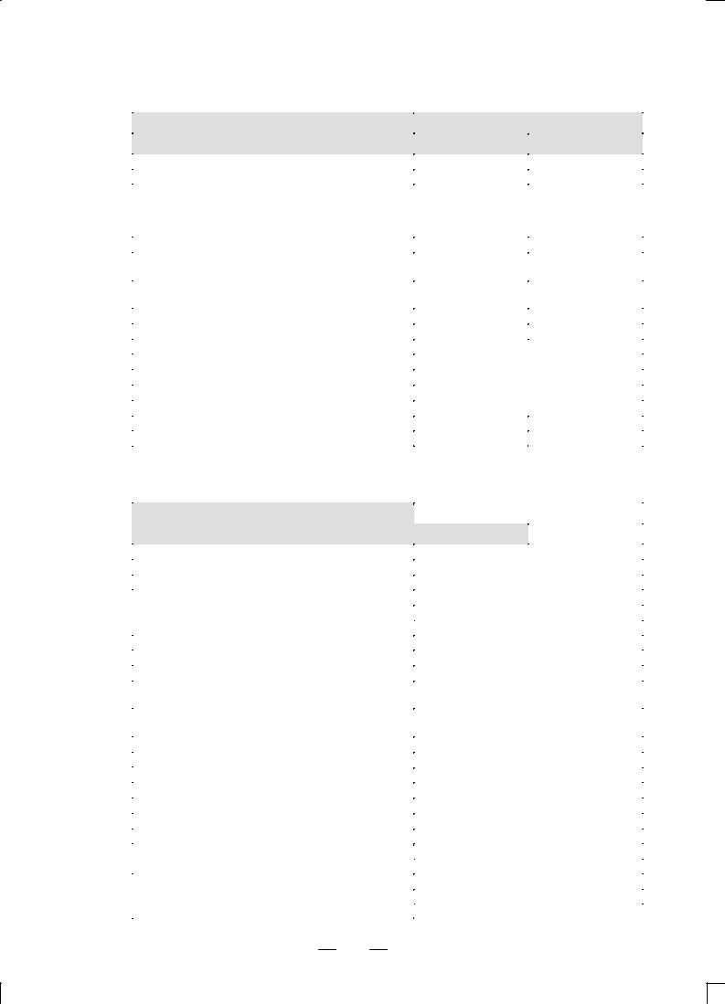
The models covered by this manual, and their abbreviations are :
Product name |
Abbreviations |
Application |
||
|
|
|
|
|
FANUC Series 16±PB |
16±PB |
Series 16 |
|
|
|
|
|
|
|
FANUC Series 160±PB |
160±PB |
Series 160 |
Punch press |
|
|
|
|
||
FANUC Series 18±PB |
18±PB |
Series 18 |
||
|
||||
|
|
|
|
|
FANUC Series 180±PB |
180±PB |
Series 180 |
|
|
|
|
|
|
|
3

1. GENERAL |
GENERAL |
B±62622EN/02 |
|
|
|
Manuals related to Series 16/160±PB, 18/180±PB
The table below lists manuals related to the FANUC Series 16/160±PB, 18/180±PB. In the table, this manual is marked with an asterisk (*).
Manuals Related to the Series 16/160±PB, 18/180±PB
Manual name |
Specification |
|
number |
|
|
|
|
|
|
|
|
FANUC Series 16/18/160/180±PB DESCRIPTIONS |
B±62622EN |
* |
|
|
|
FANUC Series 16/18/160/180±MODEL B |
B±62443E |
|
CONNECTION MANUAL (Hardware) |
|
|
|
|
|
|
|
|
FANUC Series 16/18/160/180±MODEL B |
B±62443E±1 |
|
CONNECTION MANUAL (Function) |
|
|
|
|
|
|
|
|
FANUC Series 16/18/160/180±PB |
B±62623EN |
|
CONNECTION MANUAL (Function) |
|
|
|
|
|
|
|
|
FANUC Series 16/18/160/180±PB OPERATOR'S MANUAL |
B±62624EN |
|
|
|
|
FANUC Series 16/18/160/180±MODEL B MAINTENANCE MANUAL |
B±62445E |
|
|
|
|
FANUC Series 16/18/160/180±MODEL B PARAMETER MANUAL |
B±62450E |
|
|
|
|
FANUC Series 16/18/160/180±PB PARAMETER MANUAL |
B±62630EN |
|
|
|
|
FANUC Series 16±MODEL B PROGRAMMING MANUAL |
B±61803E±1 |
|
(Macro Compiler / Macro Executer) |
|
|
|
|
|
|
|
|
FAPT MACRO COMPILER PROGRAMMING MANUAL |
B±66102E |
|
|
|
|
Manuals related to |
|
|
|
control motor α series |
Manuals related to control motor α series |
|
|
|
|
|
|
|
|
|
|
|
|
Manual name |
Specification |
|
|
number |
|
|
|
|
|
|
|
|
|
|
FANUC AC SERVO MOTOR α series DESCRIPTIONS |
B±65142E |
|
|
|
|
|
|
FANUC AC SERVO MOTOR αE series DESCRIPTIONS |
B±65182EN |
|
|
|
|
|
|
FANUC AC SERVO MOTOR α series PARAMETER MANUAL |
B±65150E |
|
|
|
|
|
|
FANUC AC SPINDLE MOTOR α series DESCRIPTIONS |
B±65152E |
|
|
|
|
|
|
FANUC AC SPINDLE MOTOR α series PARAMETER MANUAL |
B±65160E |
|
|
|
|
|
|
FANUC CONTROL MOTOR AMPLIFIER α series DESCRIPTIONS |
B±65162E |
|
|
|
|
|
|
FANUC CONTROL MOTOR α series MAINTENANCE MANUAL |
B±65165E |
|
|
|
|
|
|
FANUC CONTROL MOTOR AMPLIFIER α series |
B±65192EN |
|
|
(SERVO AMPLIFIER UNIT) DESCRIPTIONS |
||
|
|
||
|
|
|
|
|
FANUC CONTROL MOTOR AMPLIFIER α series |
B±65195EN |
|
|
(SERVO AMPLIFIER UNIT) MAINTENANCE MANUAL |
||
|
|
||
|
|
|
|
4

B±62622EN/02 GENERAL 2. LIST OF SPECIFICATIONS
2 LIST OF SPECIFICATIONS
Some functions described in this manual can be used for the 16/160±PB but cannot be used for the 18/180±PB. When selecting a function, refer to the following tables.
: Standard : Standard option : optional * : Included in another option × : Cannot be used.
Axis control
Item |
|
Description |
||
|
|
|
|
|
|
|
16/160±PB |
|
18/180±PB |
|
|
|
|
|
Controllable axes |
|
3 axes (X, Y and T |
axes) |
|
|
|
|
|
|
Expansion of controllable axes (total) (including the Cs axis |
|
8 axes max. |
4 axes max. |
|
and axes controlled by the PMC) |
|
|
|
|
Simultaneously controllable axes |
|
2 axes |
|
|
|
|
|
|
|
Expansion of simultaneously controllable axes (total) |
|
6 axes max. |
4 axes max. |
|
|
|
|
|
|
T-axis control |
|
Turret indexing |
|
|
|
|
|
|
|
C-axis control |
|
Possible |
|
|
|
|
|
|
|
Synchronous control of C-axes |
* |
Possible |
× |
Impossible |
Axis control by the PMC |
|
4 axes max. (simultaneous) |
||
|
|
|
|
|
Simple synchronous control |
|
Possible |
× |
Impossible |
Axis detach |
|
Possible |
|
|
|
|
|
||
Least input increment |
|
0.001 mm, 0.001 deg, 0.0001 inch |
||
|
0.01 mm, 0.01 deg, 0.001 inch |
|||
|
|
|||
|
|
|
|
|
Flexible feed gear |
Possible |
|
|
|
|
|
|
|
|
Dual position feed back |
Possible |
|
|
|
|
|
|
|
|
Inch/metric switching |
Possible |
|
|
|
|
|
|||
Interlock |
For all axes, each axis, or start of a cut- |
|||
|
ting block |
|
|
|
|
|
|
|
|
|
|
|||
Machine lock |
For all axes or each axis |
|||
|
|
|
|
|
Emergency stop |
Possible |
|
|
|
|
|
|
|
|
Overtravel signal |
Possible |
|
|
|
|
|
|
|
|
Stored stroke check 1 |
Possible |
|
|
|
|
|
|
|
|
External setting of stroke limit |
Possible |
|
|
|
|
|
|
|
|
Stored stroke check 2 |
Possible |
× |
Impossible |
|
Pretravel stroke check |
As specified by G00 |
|
||
|
|
|
|
|
Safety zone check |
Possible |
|
|
|
|
|
|
|
|
Mirror image |
For each axis |
|
|
|
|
|
|
|
|
Follow-up |
Possible |
|
|
|
|
|
|
|
|
Servo off/mechanical handle |
Possible |
|
|
|
|
|
|
|
|
Backlash compensation |
Possible |
|
|
|
|
|
|
|
|
Backlash compensation for rapid traverse and cutting feed |
Possible |
|
|
|
|
|
|
|
|
C-axis backlash compensation for individual indexes |
* |
Possible |
|
|
|
|
|
|
|
Stored pitch error compensation |
|
Possible |
|
|
|
|
|
|
|
Position switch |
|
Possible |
|
|
5

2. LIST OF SPECIFICATIONS |
GENERAL |
B±62622EN/02 |
|
|
|
Operation
Item |
Description |
||
|
|
|
|
|
16/160±PB |
|
18/180±PB |
|
|
|
|
Memory operation |
f Possible |
|
|
|
|
|
|
DNC operation |
f Possible |
|
|
|
|
|
|
MDI operation |
f Possible |
|
|
|
|
|
|
Program number search |
f Possible |
|
|
|
|
|
|
Stopping sequence number verification |
l Possible |
|
|
|
|
|
|
Buffer register |
f Possible |
|
|
|
|
|
|
Dry run |
f Possible |
× |
Impossible |
Single block |
f Possible |
|
|
|
|
|
|
Manual continuous feed (JOG) |
f Possible |
|
|
|
|
|
|
Manual reference position return |
f Possible |
|
|
|
|
|
|
Setting the reference position without a dog |
f Possible |
|
|
|
|
|
|
Manual handle feed |
l 1 unit |
× |
Impossible |
|
l 2 or 3 units |
× |
Impossible |
Manual handle feed magnification |
* 1, 10, xm, xn |
× |
Impossible |
|
m : 127 max., |
|
|
|
n : 1000 max. |
|
|
|
|
|
|
Manual handle interruption |
l Possible |
× |
Impossible |
Incremental feed |
f 1, 10, 100, 1000 |
||
|
|
|
|
Jogging/handle feed mode |
f Possible |
× |
Impossible |
Interpolation functions
|
Item |
Description |
||
|
|
|
|
|
|
|
16/160±PB |
|
18/180±PB |
|
|
|
|
|
Positioning |
|
f G00 |
|
|
|
|
|
|
|
Exact stop mode |
|
f G61 |
× |
Impossible |
Exact stop |
|
f G09 |
× |
Impossible |
Linear interpolation |
|
f G01 |
× |
Impossible |
Circular interpolation |
|
f Possible for multi- |
× |
Impossible |
|
|
ple quadrants |
|
|
|
|
|
|
|
Dwell (per second) |
|
f Possible |
|
|
|
|
|
|
|
Skip function |
|
f G33 |
|
|
|
|
|
|
|
Reference position return |
|
f G28 |
|
|
Feed functions
Item |
|
|
Description |
|||
|
|
|
|
|
||
|
16/160±PB |
|
18/180±PB |
|||
|
|
|
|
|
||
Rapid traverse feedrate |
f 240m/min |
|
|
|
||
|
|
|||||
Rapid traverse feedrate override |
f 25, 50, 75, 100% |
|||||
|
|
|
|
|
|
|
Feed per minute |
f mm/min |
|
|
|
|
|
|
|
|
||||
Switching rapid traverse feedrates and/or time constants |
f X- and Y-axes : |
7 steps |
||||
according to the positioning distance |
C-axis |
: |
3 steps |
|||
T-axis |
: |
3 steps (time constant only) |
||||
|
||||||
|
|
|
||||
Constant-positioning-time control |
f X- and Y-axes : |
2 steps |
||||
|
|
|
||||
|
f X- and Y-axes : |
7 steps for rapid traverse, |
||||
Servo loop gain switching |
specified for individual cutting feedrates |
|||||
|
T-axis |
: |
3 steps |
|||
6
B±62622EN/02 |
GENERAL |
|
2. LIST OF SPECIFICATIONS |
||
|
|
|
|
|
|
|
|
|
|
|
|
|
Item |
|
Description |
||
|
|
|
|
|
|
|
|
|
16/160±PB |
|
18/180±PB |
|
|
|
|
|
|
|
Constant tangential speed control |
f Possible |
× |
Impossible |
|
|
Cutting feedrate clamp |
f Possible |
× |
Impossible |
|
|
|
f Rapid traverse : |
f Rapid traverse : |
||
|
Automatic acceleration/deceleration |
|
Linear type |
|
Linear type |
|
|
Cutting feed : |
|
Cutting feed : |
|
|
|
|
|
||
|
|
|
Exponential type |
|
Not available |
|
|
|
|
|
|
|
Rapid traverse bell±type acceleration/deceleration |
l Possible |
|
|
|
|
|
|
|
|
|
|
Acceleration/deceleration after interpolation for cutting |
l Possible |
× |
Impossible |
|
|
feed |
||||
|
|
|
|
|
|
|
|
|
|
|
|
|
Acceleration/deceleration before interpolation for cutting |
l Possible |
× |
Impossible |
|
|
feed |
|
|
|
|
|
Feedrate override |
f 0±254% |
× |
Impossible |
|
|
2nd feedrate override |
f 0±254% |
× |
Impossible |
|
|
Programmable rapid traverse override |
f |
F1-digit command |
|
|
|
|
|
|
|
|
|
Jogging override |
f |
0±655.34% |
|
|
|
|
|
|
|
|
|
Override cancel |
f |
Possible |
|
|
|
|
|
|
|
|
|
External deceleration |
l |
Possible |
|
|
|
|
|
|
|
|
|
Feed stop |
l |
Possible |
|
|
|
|
|
|
|
|
|
Look ahead control function |
l |
Possible |
× |
Impossible |
|
High±speed press control function |
f Possible |
× |
Impossible |
|
|
Programming |
|
|
|
|
|
|
|
|
||
|
Item |
|
Description |
||
|
|
|
|
|
|
|
|
|
16/160±PB |
|
18/180±PB |
|
|
|
|
|
|
|
EIA/ISO automatic identification |
f Possible |
|
|
|
|
|
|
|
|
|
|
Label skip |
f Possible |
|
|
|
|
|
|
|
|
|
|
Parity check |
f Parity H, parity V |
|
|
|
|
|
|
|
|
|
|
Control in/out |
f |
|
|
|
|
|
|
|
|
|
|
Optional block skip |
f |
1 block |
|
|
|
|
|
|
|
|
|
l |
9 blocks |
|
|
|
|
|
|
|
||
|
|
|
|
|
|
|
Maximum programmable value |
f |
"8 digits |
|
|
|
|
|
|
||
|
Program number |
f |
Character O with 4 digits |
||
|
|
|
|
||
|
Sequence number |
f |
Character N with 5 digits |
||
|
|
|
|||
|
Absolute or incremental command |
f Both types of commands can be used in a |
|||
|
|
block |
|
|
|
|
|
|
|
|
|
|
|
|
|
|
|
|
Decimal point input (pocket calculator type decimal point |
f Possible |
|
|
|
|
input) |
|
|
|
|
|
10-time input unit |
f Possible |
|
|
|
|
|
|
|
|
|
|
Rotation axis setting |
f Possible |
|
|
|
|
|
|
|
|
|
|
Rotation axis roll-over |
f Possible |
|
|
|
|
|
|
|
|
|
|
Coordinate system setting |
f |
G92 |
|
|
|
|
|
|
|
|
|
Automatic coordinate system setting |
f |
Possible |
|
|
|
|
|
|
|
|
|
Workpiece coordinate system |
l |
G52, G53, G54-G59 |
|
|
|
|
|
|
|
|
|
Manual absolute on/off |
f |
Possible |
|
|
|
|
|
|
|
|
|
G code system |
f A |
|
|
|
|
|
|
|
|
|
|
f B |
|
|
||
|
|
|
|
||
|
|
|
|
|
|
|
Programmable data input |
l |
G10 |
|
|
|
|
|
|||
|
Pattern function |
f Bolt hole circle, lines at angles, etc. |
|||
|
|
|
|
|
|
|
l Linear and circular punching |
||||
|
|
||||
7

2. LIST OF SPECIFICATIONS |
GENERAL |
|
|
|
|
B±62622EN/02 |
|
|
|
|
|
|
|
|
|
|
|
|
|
|
|
|
|
|
Item |
|
|
Description |
|||
|
|
|
|
|
|
|
|
|
|
|
|
16/160±PB |
|
|
18/180±PB |
|
|
|
|
|
|
||
|
Nibbling function |
|
f As specified by G68 |
or G69 and M-codes |
|||
|
|
|
|
|
|
|
|
|
Pattern reference position command |
|
f |
G72 |
|
|
|
|
|
|
|
|
|
|
|
|
Store and call by A or B |
|
f |
5 sets |
|
|
|
|
|
|
|
|
|
|
|
|
U, V, and W macro functions |
|
f |
Possible |
|
|
|
|
|
|
|
|
|
|
|
|
Function for punching multiple products |
|
l |
Possible |
|
|
|
|
|
|
|
|
|
|
|
|
Command to restart punching multiple products |
* |
Possible |
|
|
|
|
|
|
|
|
|
|
||
|
Repositioning command |
|
f |
As specified by G75 and M-codes |
|||
|
|
|
|
|
|
|
|
|
Bending allowance compensation |
|
f |
G38/G39 |
|
|
|
|
|
|
|
|
|
|
|
|
Subprogram calling |
|
f |
Fourfold nesting |
|
|
|
|
|
|
|
|
|
|
|
|
Custom macro |
|
l |
Possible |
|
|
|
|
|
|
|
|
|
|
|
|
Additional custom macro common variables |
l |
#532-#999 |
|
|
|
|
|
|
|
|
|
|
|
|
|
Interruption type custom macro |
|
l |
Possible |
|
|
|
|
|
|
|
|
|
|
|
|
Specifying the radius of an arc |
|
f |
Possible |
× |
Impossible |
|
|
Automatic corner override |
|
l |
Possible |
× |
Impossible |
|
|
Automatic corner deceleration |
|
l |
Possible |
× |
Impossible |
|
|
Speed clamp by the radius of an arc |
|
l |
Possible |
× |
Impossible |
|
|
Scaling |
|
l |
Possible |
|
|
|
|
|
|
|
|
|
|
|
|
Coordinate rotation |
|
l |
Possible |
|
|
|
|
|
|
|
|
|
|
|
|
Conversational graphic programming |
|
l |
Possible |
|
|
|
|
|
|
|
|
|
|
|
|
Macro executor |
|
l |
3M bytes max. |
|
|
|
|
|
|
|
|
|
|
|
|
C language executer |
|
l |
3M bytes max. |
|
|
|
|
|
|
|
|
|
|
|
|
MMC ± III |
|
l |
Possible |
|
|
|
|
|
|
|
|
|
|
|
|
MMC ± IV |
|
l |
Possible |
|
|
|
|
|
|
|
|
|
|
|
|
One-cycle press |
|
f |
Possible |
|
|
|
|
|
|
|
|
|
|
|
|
Continuous press (nibbling) |
|
f |
Possible |
|
|
|
|
|
|
|
|
|
||
|
Manual press |
|
f |
One-cycle or continuous press |
|||
|
|
|
|
|
|
|
|
|
Positioning and no press start signal |
|
f |
G70 |
|
|
|
|
|
|
|
|
|
|
|
|
Setting up press start signal output conditions |
f |
Early PF |
|
|
|
|
|
|
|
|
|
|
|
|
|
Press activation lock |
|
f |
Possible |
|
|
|
|
|
|
|
|
|
|
|
|
Deferring press activation |
|
f |
Possible |
|
|
|
|
|
|
|
|
|
|
|
|
Switching between two nibbling pitches |
|
f |
Nibbling pitch switching |
|
||
|
|
|
|
|
|
|
|
|
External operation function |
|
f EF output |
|
|
|
|
|
Miscellaneous functions and spindle-speed functions |
|
|
|
|||
|
|
|
|
|
|
||
|
Item |
|
|
Description |
|||
|
|
|
|
|
|
|
|
|
|
|
|
16/160±PB |
|
|
18/180±PB |
|
|
|
|
|
|||
|
Miscellaneous function |
|
f Character M with 8 digits |
||||
|
|
|
|
||||
|
2nd miscellaneous function |
|
l Character B with 8 digits |
||||
|
|
|
|
|
|
|
|
|
Miscellaneous function lock |
|
f Possible |
|
|
|
|
|
|
|
|
|
|
|
|
|
High-speed M/S/T interface |
|
f Possible |
|
|
|
|
|
|
|
|
|
|
||
|
Multiple M commands specified in single block |
f Three commands |
|
|
|
||
|
|
|
|
|
|
||
|
Spindle-speed function |
|
f Character S with 5 |
|
× |
Impossible |
|
|
|
|
|
digits, binary output |
|
|
|
|
|
|
|
|
|
|
|
|
Spindle speed control by the PMC |
|
* |
Possible |
|
× |
Impossible |
8

B±62622EN/02 |
GENERAL |
2. LIST OF SPECIFICATIONS |
|
|
|
Tool functions and tool compensation functions
Item |
|
Description |
||
|
|
|
|
|
|
|
16/160±PB |
|
18/180±PB |
|
|
|
|
|
|
f T and 8 digits |
|
|
|
Tool function |
f T-axis control: |
|
|
|
|
|
Code consisting of T and up to 4 digits |
||
|
|
|
|
|
Tool registration |
f |
136 tools |
|
|
|
|
|||
Tool offset compensation |
f Positive or negative number consisting of 8 |
|||
|
digits |
|
|
|
|
|
|
|
|
|
|
|
|
|
Ignoring T-codes |
f Possible |
|
|
|
|
|
|
|
|
Multiple-tool control |
l Possible |
|
|
|
|
|
|
|
|
C-axis position compensation |
* |
20 tools |
|
|
|
|
|
|
|
|
* |
"6 digits, 32 units |
× |
Impossible |
|
l |
"6 digits, 64 units |
× |
Impossible |
Tool compensation memory |
l |
"6 digits, 99 units |
× |
Impossible |
|
l |
"6 digits, 200 units |
× |
Impossible |
|
l |
"6 digits, 400 units |
× |
Impossible |
Cutter compensation C |
l |
Possible |
× |
Impossible |
Tool life management |
l |
Possible |
|
|
Editing
Item |
|
Description |
|
|
|
|
|
|
|
16/160±PB |
18/180±PB |
|
|
|
|
Part program storage length |
±±±±±±±±±±±±±±±±± |
f 10 m |
|
|
|
|
|
|
f |
20 m |
l 20 m |
|
|
|
|
|
l |
40 m |
|
|
|
|
|
|
l |
80 m |
|
|
|
|
|
|
l |
160 m |
|
|
|
|
|
|
l |
320 m |
|
|
|
|
|
|
l |
640 m |
|
|
|
|
|
|
l |
1280 m |
|
|
|
|
|
Number of registered programs |
f |
63 programs |
|
|
|
|
|
|
l |
125 programs |
|
|
|
|
|
|
l |
200 programs |
|
|
|
|
|
|
l |
400 programs |
|
|
|
|
|
|
l |
1000 programs |
|
|
|
|
|
Part program storage and editing |
f |
Possible |
|
|
|
|
|
Program protection |
f |
Possible |
|
|
|
|
|
Password function |
f |
Possible |
|
|
|
|
|
Background editing |
l |
Possible |
|
|
|
|
|
Extended tape editing |
l |
Possible |
|
|
|
|
|
Machining time stamp function |
l |
Possible |
|
9

2. LIST OF SPECIFICATIONS |
GENERAL |
B±62622EN/02 |
|
|
|
Setting and display
Item |
|
Description |
|
|
|
|
|
|
|
|
|
16/160±PB |
|
18/180±PB |
|
|
|
|
|
Status display |
f Possible |
|
|
|
|
|
|
||
Clock function |
f Possible |
|
||
|
|
|
||
Current position display |
f Possible |
|
||
|
|
|||
Program display |
f Program name: 16 characters |
|||
|
|
|
||
Parameter setting display |
f Possible |
|
||
|
|
|
||
Self diagnosis |
f Possible |
|
||
|
|
|
||
Alarm display |
f Possible |
|
||
|
|
|||
Alarm history display |
f PMC alarm message, macro alarm mes- |
|||
|
sage |
|
||
|
|
|
||
|
|
|
|
|
Operator message history display |
* |
Possible |
|
|
|
|
|
|
|
Operation history display |
f |
Possible |
|
|
|
|
|
|
|
Remote diagnosis function |
l |
Possible |
|
|
|
|
|
|
|
Help function |
f |
Possible |
|
|
|
|
|
|
|
Operation time and number-of-parts display |
l |
Possible |
|
|
|
|
|
|
|
Actual speed display |
f |
Possible |
|
|
|
|
|
|
|
Floppy Cassette directory display |
l |
Possible |
|
|
|
|
|
|
|
Graphic display |
l |
Possible |
|
|
|
|
|
|
|
Servo adjustment screen |
f |
Possible |
|
|
|
|
|
|
|
Servo waveform display |
* |
Possible |
|
|
|
|
|
|
|
Hard/soft system configuration display |
f |
Possible |
|
|
|
|
|
||
Software operator's panel |
l Possible |
|
||
|
|
|
|
|
General-purpose switches on the software operator's |
l Possible |
|
||
panel |
|
|||
|
|
|
|
|
|
|
|
||
|
f English |
|
||
|
|
|
||
|
l Japanese (kanji) |
|
||
|
|
|
||
Language selection |
l German |
|
||
|
|
|
|
|
l French |
|
|||
|
|
|||
|
|
|
||
|
l Italian |
|
||
|
|
|
||
|
l Spanish |
|
||
|
|
|
|
|
Data protection key |
f |
3 types |
|
|
Data input/output
Item |
|
Description |
|||
|
|
|
|
||
|
16/160±PB |
|
|
18/180±PB |
|
|
|
|
|||
Reader/punch interface |
l Reader/punch (Ch 1) interface |
||||
|
|
|
|
||
l Reader/punch (Ch 2) interface |
|||||
|
|||||
|
|
|
|
|
|
Simultaneous I/O operation |
l Possible |
|
|
|
|
|
|
|
|
|
|
Remote buffer |
l Possible |
|
|
|
|
|
|
|
|
|
|
I/O device external control |
l Possible |
|
|
|
|
|
|
|
|
||
DNC1 control |
l Possible |
|
× |
Impossible |
|
DNC2 control |
l Possible |
|
× |
Impossible |
|
|
|
|
|
|
|
External tool compensation |
l Possible |
|
× |
Impossible |
|
|
|
|
|
|
|
External message |
l Possible |
|
|
|
|
|
|
|
|
|
|
External machine origin shift |
l Possible |
|
|
|
|
|
|
|
|
|
|
External data input |
l Possible |
|
|
|
|
|
|
|
|
|
|
External workpiece number search |
f 31 numbers |
|
|
|
|
|
|
|
|
|
|
External program number search |
l 1±9999 |
|
|
|
|
10

B±62622EN/02 |
|
GENERAL |
|
2. LIST OF SPECIFICATIONS |
||||
|
|
|
|
|
|
|
|
|
|
|
|
|
|
|
|
|
|
|
|
Item |
|
Description |
|
|
|
|
|
|
|
|
|
|
|
|
|
|
|
|
|
16/160±PB |
|
18/180±PB |
||
|
|
|
|
|
|
|
|
|
|
FANUC FA Card |
|
Possible |
|
|
|
|
|
|
|
|
|
|
|
|
|
|
|
FANUC Handy File |
|
Possible |
|
|
|
||
|
|
|
|
|
|
|
|
|
|
FANUC FLOPPY CASSETTE |
|
Possible |
|
|
|
||
|
|
|
|
|
|
|
|
|
|
FANUC PROGRAM FILE Mate |
|
Possible |
|
|
|
||
|
|
|
|
|
|
|
|
|
|
FANUC PPR |
|
|
Possible |
|
|
|
|
|
|
|
|
|
|
|
|
|
|
Memory card inteface |
|
Possible |
|
|
|
||
|
Others |
|
|
|
|
|
|
|
|
|
|
|
|
|
|
|
|
|
|
Item |
|
Description |
|
|
|
|
|
|
|
|
|
|
|
|
|
|
|
|
|
16/160±PB |
|
|
18/180±PB |
|
|
|
|
|
|
|
|
||
|
Abnomal load detection |
Possible |
|
|
|
|||
|
|
|
|
|||||
|
|
|
NC ready, servo ready, automatic operation, |
|||||
|
|
|
|
automatic operation start lamp, feed hold, re- |
||||
|
Status output signal |
|
set, NCalarm, distribution end, rewinding, inch |
|||||
|
|
|
|
input, cutting, inposition, thread cutting, tap- |
||||
|
|
|
|
ping, etc. |
|
|
|
|
|
|
|
|
|||||
|
|
|
9º monochrome CRT/MDI (small size) |
|||||
|
|
|
|
|||||
|
|
|
9º monochrome CRT/MDI (standard size) |
|||||
|
|
|
|
|
|
|
||
|
|
|
9º color CRT/MDI (small size) |
|
|
|
||
|
|
|
|
|
||||
|
|
|
9º color CRT/MDI (standard size) |
|
||||
|
|
|
|
|||||
|
|
|
9º monochrome PDP/MDI (standard size) |
|||||
|
|
|
|
|||||
|
|
|
14º color CRT/MDI (horizontal type) |
|||||
|
|
|
|
|
||||
|
|
|
14º color CRT/MDI (vertial type) |
|
||||
|
|
|
|
|||||
|
Setting and display unit |
9º monochrome CRT (separate type) |
||||||
|
|
|
|
|
|
|
||
|
|
|
9º color CRT (separate type) |
|
|
|
||
|
|
|
|
|||||
|
|
|
9º monochrome PDP (separate type) |
|||||
|
|
|
|
|
||||
|
|
|
8.4º color LCD (separate type) |
|
||||
|
|
|
|
|||||
|
|
|
9.5º color LCD/MDI (horizontal type) |
|||||
|
|
|
|
|
||||
|
|
|
9.5º color CRT/MDI (vertial type) |
|
||||
|
|
|
|
|
|
|
||
|
|
|
Separate MDI (small size) |
|
|
|
||
|
|
|
|
|
|
|
||
|
|
|
Separate MDI (standard size) |
|
|
|
||
|
|
|
|
|
|
|
||
|
|
PMC±RB3, PMC±RB4 |
Basic instruction : 1.0ms/step |
|
|
|
||
|
|
|
Max. step number ladder : 24000 |
|
||||
|
|
|
|
|
||||
|
|
|
|
|
|
|||
|
|
|
Basic instruction : 0.10ms/step |
× |
|
|||
|
PMC |
|
|
Max. step number ladder : |
|
Impossible |
||
|
|
24000 |
|
|
|
|
||
|
system |
|
|
|
|
|
||
|
|
|
|
|
|
|
|
|
|
PMC±RC3, PMC±RC4 |
C language : Max. 2MB |
|
× |
Impossible |
|||
|
|
|
||||||
|
|
|
Nonvolatile memory expan- |
|
× |
Impossible |
||
|
|
|
|
sion |
|
|||
|
|
|
|
|
|
|
||
|
|
|
|
|
|
|
||
|
|
|
Signal waveform display |
|
× |
Impossible |
||
|
|
|
Sink type output |
|
|
|
||
|
Machine interface (I/O Card) |
|
Max. DI/DO points : 156/120 |
|
|
|
||
|
(Available 1or 2 card) |
Source type output A |
|
|
|
|||
|
|
|
|
Max. DI/DO points : 104/72 |
|
|
|
|
|
|
|
|
|
|
|
||
|
|
|
I/O Unit MODEL A |
|
|
|
||
|
|
|
|
|
|
|
||
|
Machine interface (I/O Link) |
I/O Unit MODEL B |
|
|
|
|||
|
|
|
|
|
|
|
||
|
Operator's panel connection unit |
|
||||||
|
Max. DI/DO points : 1024/1024 points |
|
||||||
|
|
Max. DI/DO points : 96/64 |
|
|
|
|||
|
|
|
|
|
|
|
||
|
|
|
|
|||||
|
|
|
Machine operator's panel interface unit |
|||||
|
|
|
|
|||||
|
Connectable servo motor |
FANUC AC servo motor (with serial interface |
||||||
|
|
pulse coder) |
|
|
|
|||
|
|
|
|
|
|
|
||
|
|
|
||||||
|
Connectable servo amp |
FANUC AC servo amp (digital servo) |
||||||
11
2. LIST OF SPECIFICATIONS |
GENERAL |
|
B±62622EN/02 |
|||
|
|
|
|
|
|
|
|
|
|
|
|
|
|
|
|
|
Item |
Description |
|
|
|
|
|
|
|
|
|
|
|
|
|
16/160±PB |
|
18/180±PB |
|
|
|
|
|
||
|
Connectable position detector (for full±closed control) |
Pulse coder / optical scale (2±phase pluse in- |
||||
|
|
|
|
terface) |
|
|
|
|
2 slots |
|
112(W) 380(H) 172(D) mm |
|
|
|
|
|
|
|
|
|
|
Control unit |
3 slots |
|
172(W) 380(H) 172(D) mm |
|
|
|
|
|
|
|
|
|
|
4 slots |
|
224(W) 380(H) 172(D) mm |
|
|
|
|
dimensions |
|
|
|
||
|
|
|
|
|
|
|
|
|
6 slots |
|
336(W) 380(H) 172(D) mm |
× |
Impossible |
|
|
8 slots |
|
448(W) 380(H) 172(D) mm |
× |
Impossible |
|
Input power supply |
|
200 to 240 VAC )10%, *15% |
|
|
|
|
|
50 to 60Hz"3Hz |
|
|
||
|
|
|
|
|
|
|
12

II. NC FUNCTION

B±62622EN/02 |
NC FUNCTION |
1. CONTROLLED AXES |
|
|
|
1 CONTROLLED AXES
1.1
NUMBER OF THE ALL CONTROLLED AXES
1.2
8 axes
The machine controlled axes include Cs axis and PMC controlled axes.
MACHINE
CONTROLLED AXES
1.2.1 |
3 axes (X axis, Y axis, turret axis (T axis)) |
Number of Basic |
|
Controlled Axes |
|
|
|
1.2.2 |
2 axes |
Number of Basic |
|
Simultaneously |
|
Controlled Axes |
|
|
|
1.2.3 |
8 axes (including PMC controlled axes) |
Number of Controlled |
|
Axes Expanded (All) |
|
|
|
1.2.4 |
Max. 6 axes |
Number of |
|
Simultaneously |
|
Controlled Axes |
|
Expanded (All) |
|
|
|
1.2.5 |
Max. simultaneous 4 axes |
Axis Control by PMC |
|
15

1. CONTROLLED AXES |
NC FUNCTION |
B±62622EN/02 |
|
|
|
1.3
AXIS NAMES
Notes
X, Y, T, and C
The names of the two basic axes are always X and Y. The name of an additional axis can be selected from A, B, C, U, V, W, and T.
Notes
When A, B, U, V, or W is used as an axis name, some functions are disabled accordingly (AB macro function, UVW macro function, and multi±piece cutting function).
16
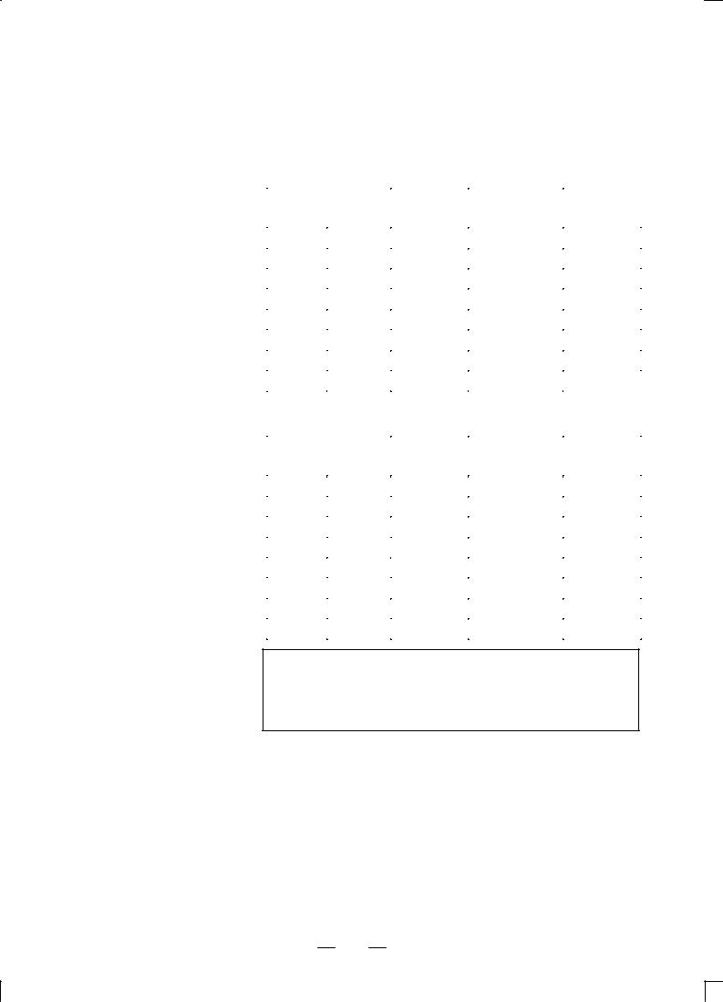
B±62622EN/02 |
NC FUCNTION |
1. CONTROLLED AXES |
|
|
|
1.4
INCREMENT SYSTEM
There are two increment systems as shown in the tables below. One of the increment systems can be selected using a parameter.
Table 1.4(a)
|
|
Least input |
Least command |
Abbreviation |
|
|
increment |
increment |
|
|
|
|
||
|
|
|
|
|
|
Metric input |
0.01 mm |
0.005 mm |
|
|
|
|
|
|
Millimeter |
0.01 deg |
0.01 deg |
|
|
|
|
|||
|
|
|
|
|
machine |
Inch input |
0.001 inch |
0.005 mm |
|
|
|
|||
|
|
|
|
|
|
0.01 deg |
0.01 deg |
IS±A |
|
|
|
|||
|
|
|
|
|
|
Metric input |
0.01 mm |
0.0005 inch |
|
|
|
|||
|
|
|
|
|
Inch |
0.01 deg |
0.01 deg |
|
|
|
|
|||
|
|
|
|
|
machine |
Inch input |
0.001 inch |
0.0005 inch |
|
|
|
|||
|
|
|
|
|
|
0.01 deg |
0.01 deg |
|
|
|
|
|
||
|
|
|
|
|
Table 1.4(b)
|
|
Least input |
Least command |
Abbreviation |
|
|
increment |
increment |
|
|
|
|
||
|
|
|
|
|
|
Metric input |
0.001 mm |
0.0005 mm |
|
|
|
|
|
|
Millimeter |
0.001 deg |
0.001 deg |
|
|
|
|
|||
|
|
|
|
|
machine |
Inch input |
0.0001 inch |
0.0005 mm |
|
|
|
|||
|
|
|
|
|
|
0.001 deg |
0.001 deg |
IS±B |
|
|
|
|||
|
|
|
|
|
|
Metric input |
0.001 mm |
0.00005 inch |
|
|
|
|||
|
|
|
|
|
Inch |
0.001 deg |
0.001 deg |
|
|
|
|
|||
|
|
|
|
|
machine |
Inch input |
0.0001 inch |
0.00005 inch |
|
|
|
|||
|
|
|
|
|
|
0.001 deg |
0.001 deg |
|
|
|
|
|
||
|
|
|
|
|
Notes
For the turrent axis (called T-axis), the least command increment is determined according to the distance the tool travels each time the turret makes one turn.
The least command increment is in millimeters or inches, depending on the machine tool. One of them must be selected using a parameter beforehand.
The least input increment can be switched between metric input and inch input by using a G code (G20 or G21) or a setting parameter.
17

1. CONTROLLED AXES |
NC FUNCTION |
B±62622EN/02 |
|
|
|
1.4.1
Input Unit (10 Times)
The following least input increments can be set using a parameter:
Increment system |
Least input increment |
|
|
IS±B |
0.01 mm, 0.01 deg, or 0.001 inch |
|
|
When incerement system is IS-A, Input unit 10 time multibly can not be used.
18
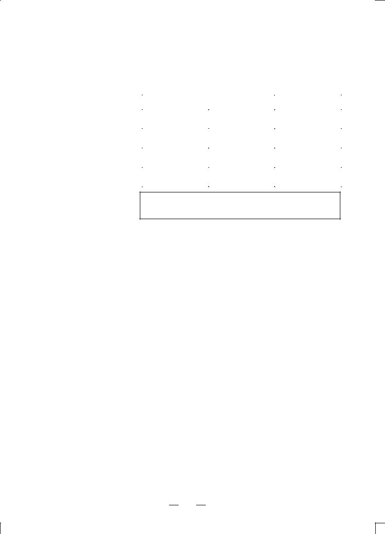
B±62622EN/02 |
NC FUCNTION |
1. CONTROLLED AXES |
|
|
|
1.5
MAXIMUM STROKE
The following table lists the maximum strokes of machine tools that are allowed by the control unit:
Maximum stroke = Least command increment 99999999
Increment system |
Maximum stroke |
||
|
|
|
|
|
Millimeter machine |
±999999.99 mm |
|
|
±999999.99 deg |
||
IS±A |
|
||
|
|
||
Inch machine |
±99999.999 inch |
||
|
|||
|
±999999.99 deg |
||
|
|
||
|
|
|
|
|
Millimeter machine |
±99999.999 mm |
|
|
±99999.999 deg |
||
IS±B |
|
||
|
|
||
Inch machine |
±9999.9999 inch |
||
|
|||
|
±99999.999 deg |
||
|
|
||
|
|
|
|
Notes
A command that exceeds the maximum stroke is not allowed.
19

2. PREPARATORY FUNCTIONS |
NC FUNCTION |
B±62622EN/02 |
|
|
|
2 PREPARATORY FUNCTIONS
The following G codes are provided. The G codes are classified into two: A and B. One of the G code types can be selected using a parameter. In this manual, G code system B is assumed.
|
|
|
G code list (1/2) |
System A |
System B |
Group |
Meaning |
|
|
|
|
G00l |
G00l |
|
Positioning (Rapid traverse) |
|
|
|
|
G01l |
G00l |
01 |
Linear interpolation (Cutting feed) |
|
|
|
|
G02 |
G02 |
|
Circular interpolation (CW) |
|
|
|
|
G03 |
G03 |
|
Circular interpolation (CCW) |
|
|
|
|
G04 |
G04 |
|
Dwell |
|
|
|
|
G08 |
G08 |
|
Look±ahead cotrol |
|
|
|
|
G09 |
G09 |
00 |
Exact stop |
|
|
|
|
G10 |
G10 |
|
Data setting |
|
|
|
|
G11 |
G11 |
|
Data setting mode cancel |
|
|
|
|
G20 |
G20 |
06 |
Input in inch |
|
|
|
|
G21 |
G21 |
|
Input in mm |
|
|
|
|
G22l |
G22l |
04 |
Stored stroke limit function on |
|
|
|
|
G23 |
G23 |
|
Stored stroke limit function off |
|
|
|
|
G26 |
G26 |
|
Bolt hole circle |
|
|
|
|
G28 |
G28 |
|
Automatic reference point return |
|
|
|
|
G32 |
G32 |
00 |
Automatic safety zone setting |
|
|
|
|
G33 |
G33 |
|
Skip function |
|
|
|
|
G38 |
G38 |
|
Bending compensation X |
|
|
|
|
G39 |
G39 |
|
Bending compensation Y |
|
|
|
|
G40l |
G40l |
|
Cutter compensation cancel |
|
|
|
|
G41 |
G41 |
07 |
Cutter compensation left |
|
|
|
|
G42 |
G42 |
|
Cutter compensation right |
|
|
|
|
G45 |
G45 |
|
Linear punching |
|
|
|
|
G46 |
G46 |
00 |
Circular punching (CW) |
|
|
|
|
G47 |
G47 |
|
Circular punching (CCW) |
|
|
|
|
G50l |
G34l |
11 |
Scaling on |
|
|
|
|
G51 |
G35 |
|
Scaling off |
|
|
|
|
G52 |
G93 |
0 |
Local coordinate system setting |
|
|
|
|
G53 |
G53 |
00 |
Machine coordinate system selection |
|
|
|
|
G54 |
G54 |
|
Workpiece coordinates system 1 selection |
|
|
|
|
G55 |
G55 |
|
Workpiece coordinates system 2 selection |
|
|
|
|
G56 |
G56 |
14 |
Workpiece coordinates system 3 selection |
|
|
|
|
G57 |
G57 |
|
Workpiece coordinates system 4 selection |
|
|
|
|
G58 |
G58 |
|
Workpiece coordinates system 5 selection |
|
|
|
|
20

B±62622EN/02 |
|
|
NC FUCNTION |
2. PREPARATORY FUNCTIONS |
||
|
|
|
|
|
|
|
|
|
|
|
G code list (2/2) |
|
|
|
|
|
|
|
|
|
|
System A |
System B |
Group |
|
Meaning |
|
|
|
|
|
|
|
|
|
G59 |
G59 |
14 |
Workpiece coordinates system 6 selection |
|
|
|
|
|
|
|
|
|
|
G61 |
G61 |
|
Exact stop mode |
|
|
|
|
|
|
|
|
|
|
G62 |
G62 |
15 |
Automatic corner override |
|
|
|
|
|
|
|
|
|
|
G64l |
G64l |
|
Continuous cutting mode |
|
|
|
|
|
|
|
|
|
|
G65 |
G95 |
00 |
Custom macro simple call |
|
|
|
|
|
|
|
|
|
|
G66 |
G96 |
12 |
Custom macro modal call |
|
|
|
|
|
|
|
|
|
|
G67l |
G97l |
|
Custom macro modal call cancel |
|
|
|
|
|
|
|
|
|
|
G68 |
G68 |
|
Circular nibbling |
|
|
|
|
|
|
|
|
|
|
G69 |
G69 |
|
Linear nibbling |
|
|
|
|
|
|
|
|
|
|
G70 |
G70 |
|
Positioning & press off |
|
|
|
|
|
|
|
|
|
|
G72 |
G72 |
|
Standard point command |
|
|
|
|
|
|
|
|
|
|
G73 |
G75 |
|
Multi-piece machining command X |
|
|
|
|
|
|
|
|
|
|
G74 |
G76 |
00 |
Multi-piece machining command Y |
|
|
|
|
|
|
|
|
|
|
G75 |
G27 |
|
Automatic repositioning |
|
|
|
|
|
|
|
|
|
|
G76 |
G28 |
|
Line at angle |
|
|
|
|
|
|
|
|
|
|
G77 |
G29 |
|
Arc |
|
|
|
|
|
|
|
|
|
|
G78 |
G36 |
|
Grid I |
|
|
|
|
|
|
|
|
|
|
G79 |
G37 |
|
Grid II |
|
|
|
|
|
|
|
|
|
|
G84 |
G84 |
16 |
Coordinate rotating on |
|
|
|
|
|
|
|
|
|
|
G85l |
G85l |
|
Coordinate rotating off |
|
|
|
|
|
|
|
|
|
|
G86 |
G86 |
|
Share proof |
|
|
|
|
|
|
|
|
|
|
G87 |
G87 |
00 |
Square |
|
|
|
|
|
|
|
|
|
|
G88 |
G78 |
|
Radius |
|
|
|
|
|
|
|
|
|
|
G89 |
G79 |
|
Cut at angle |
|
|
|
|
|
|
|
|
|
|
G90l |
G90l |
03 |
Absolute command |
|
|
|
|
|
|
|
|
|
|
G91l |
G91l |
|
Incremental command |
|
|
|
|
|
|
|
|
|
|
G92 |
G92 |
00 |
Coordinate system setting |
|
|
|
|
|
|
|
|
|
|
G98 |
G98 |
|
Coordinate system setting (Multi-piece machining) |
|
|
|
|
|
|
|
|
|
21

3. INTERPOLATION FUNCTIONS |
NC FUNCTION |
B±62622EN/02 |
|
|
|
3 INTERPOLATION FUNCTIONS
22
Loading...