


GE Fanuc Automation
Computer Numerical Control Products
I/O Link―II
Connection Manual
GFZ-62714EN/04 |
February 2001 |

GFL-001
Warnings, Cautions, and Notes as Used in this Publication
Warning
Warning notices are used in this publication to emphasize that hazardous voltages, currents, temperatures, or other conditions that could cause personal injury exist in this equipment or may be associated with its use.
In situations where inattention could cause either personal injury or damage to equipment, a Warning notice is used.
Caution
Caution notices are used where equipment might be damaged if care is not taken.
Note
Notes merely call attention to information that is especially significant to understanding and operating the equipment.
This document is based on information available at the time of its publication. While efforts have been made to be accurate, the information contained herein does not purport to cover all details or variations in hardware or software, nor to provide for every possible contingency in connection with installation, operation, or maintenance. Features may be described herein which are not present in all hardware and software systems. GE Fanuc Automation assumes no obligation of notice to holders of this document with respect to changes subsequently made.
GE Fanuc Automation makes no representation or warranty, expressed, implied, or statutory with respect to, and assumes no responsibility for the accuracy, completeness, sufficiency, or usefulness of the information contained herein. No warranties of merchantability or fitness for purpose shall apply.
©Copyright 2001 GE Fanuc Automation North America, Inc.
All Rights Reserved.

B-62714EN/04 |
SAFETY PRECAUTIONS |
SAFETY PRECAUTIONS
This section describes the safety precautions related to the use of CNC units, to ensure safe operation of machines fitted with FANUC CNC units. Read this section carefully before attempting to use any function described in this manaul.
Users should also read the relevant descriptions in the Operator’s Manual to become fully familiar with the functions to be used.
|
CONTENTS |
|
1. |
DEFINITION OF WARNING, CAUTION, AND NOTE |
.........s-2 |
2. |
GENERAL WARNINGS AND NOTES ................................... |
s-3 |
s - 1

SAFETY PRECAUTIONS |
B-62714EN/04 |
1 DEFINITION OF WARNING, CAUTION, AND NOTE
This manual includes safety precautions for protecting the user and preventing damage to the machine. Precautions are classified into Warning and Caution according to their bearing on safety. Also, supplementary information is described as a Note. Read the Warning, Caution, and Note thoroughly before attempting to use the machine.
WARNING
Applied when there is a danger of the user being injured or when there is a damage of both the user being injured and the equipment being damaged if the approved procedure is not observed.
CAUTION
Applied when there is a danger of the equipment being damaged, if the approved procedure is not observed.
NOTE
The Note is used to indicate supplementary information other than Warning and Caution.
- Read this manual carefully, and store it in a safe place.
s - 2

B-62714EN/04 |
SAFETY PRECAUTIONS |
2 GENERAL WARNINGS AND NOTES
WARNING
1Before operating the machine, thoroughly check the entered data.
Operating the machine with incorrect data may result in the machine behaving unexpectedly, possibly causing damage to the workpiece and/or machine itself, or injury to the user.
2Never attempt to perform a production run, such as actually machining a workpiece, without first checking the operation of the machine. Before starting the machine for a production run, ensure that the program command values, offsets, current position, external signals, and other settings are suitable for the operation to be performed. Also check that the machine operates correctly by performing a trial run using, for example, the single block, feedrate override, or machine lock function or by operating the machine with neither a tool nor workpiece mounted.
3Ensure that the specified feedrate is appropriate for the intended operation. Generally, for each machine, there is a maximum allowable feedrate.
The appropriate feedrate varies with the intended operation. Refer to the manual provided with the machine to determine the maximum allowable feedrate.
If a machine is run at other than the correct speed, it may behave unexpectedly, possibly causing damage to the workpiece and/or machine itself, or injury to the user.
4When using a tool compensation function, thoroughly check the direction and amount of compensation.
Operating the machine with incorrectly specified data may result in the machine behaving unexpectedly, possibly causing damage to the workpiece and/or machine itself, or injury to the user.
s - 3

SAFETY PRECAUTIONS |
B-62714EN/04 |
WARNING
5The parameters for the CNC and PMC are factoryset. Usually, there is not need to change them. When, however, there is not alternative other than to change a parameter, ensure that you fully understand the function of the parameter before making any change.
Failure to set a parameter correctly may result in the machine behaving unexpectedly, possibly causing damage to the workpiece and/or machine itself, or injury to the user.
6Immediately after switching on the power, do not touch any of the keys on the MDI panel until the position display or alarm screen appears on the
CNC unit.
Some of the keys on the MDI panel are dedicated to maintenance or other special operations. Pressing any of these keys may place the CNC unit in other than its normal state. Starting the machine in this state may cause it to behave unexpectedly.
7The operator's manual and programming manual supplied with a CNC unit provide an overall description of the machine's functions, including any optional functions. Note that the optional functions will vary from one machine model to another. Therefore, some functions described in the manuals may not actually be available for a particular model.
Check the specification of the machine if in doubt.
8Some functions may have been implemented at the request of the machine-tool builder. When using such functions, refer to the manual supplied by the machine-tool builder for details of their use and any related cautions. Refer to the following two examples.
<1> Some machines have a tool replacement device that operates when a tool feature is executed. When the user is working near the device, he or she may touch it. Execute tool features in a place sufficiently away from the tool replacement device.
<2> Many auxiliary features cause machine operation such as rotation of the spindle. Understand the operations of auxiliary features before using them.
s - 4

B-62714EN/04 |
SAFETY PRECAUTIONS |
NOTE
Command programs, parameters, and variables are stored in nonvolatile memory in the CNC unit. Usually, they are retained even if the power is turned off. Such data may be delated inadvertently, however, or it may prove necessary to delete all data from nonvolatile memory as part of error recovery. To guard against the occurrence of the above, and assure quick restoration of deleted data, backup all vital data, and keep the backup copy in a safe place.
s - 5

B-62714EN/04 |
Table of Contents |
Table of Contents
SAFETY PRECAUTIONS....................................................................................................................... |
s-1 |
||
I. GENERAL |
|
||
1 |
GENERAL........................................................................................................................................... |
3 |
|
|
1.1 |
ORGANIZATION .............................................................................................................................. |
4 |
|
1.2 |
APPLICABLE MODELS................................................................................................................... |
5 |
II. SPECIFICATIONS |
|
||
1 |
I/O Link-II I/O FUNCTION................................................................................................................ |
9 |
|
|
1.1 |
FEATURES...................................................................................................................................... |
10 |
|
1.2 |
MASTER FUNCTION..................................................................................................................... |
11 |
|
1.3 |
SLAVE FUNCTION ........................................................................................................................ |
12 |
|
1.4 |
SPECIFICATIONS.......................................................................................................................... |
13 |
|
1.5 |
GLOSSARY...................................................................................................................................... |
16 |
III. OPERATION |
|
||
1 |
16/18/21-B, 16/18-C, LCD-MOUNTED TYPE 16i/18i/21i-A............................................................ |
21 |
|
|
1.1 |
MASTER FUNCTION..................................................................................................................... |
22 |
|
1.2 |
SLAVE FUNCTION ........................................................................................................................ |
32 |
|
1.3 |
DATA CONCURRENCY................................................................................................................. |
42 |
2 |
LCD-MOUNTED TYPE 16i/18i/21i-A, Power Mate i-D/H .............................................................. |
44 |
|
|
2.1 |
MASTER FUNCTION..................................................................................................................... |
45 |
|
2.2 |
SLAVE FUNCTION ........................................................................................................................ |
61 |
|
2.3 |
DATA CONCURRENCY................................................................................................................. |
80 |
3 |
Power Mate-D/F/H............................................................................................................................ |
82 |
|
|
3.1 |
SLAVE FUNCTION ........................................................................................................................ |
83 |
|
3.2 |
DATA CONCURRENCY................................................................................................................. |
92 |
c - 1
Table of Contents |
B - 62714EN/04 |
||
IV. CONNECTION |
|
||
1 |
COMMUNICATION FUNCTION CONNECTION |
.......................................................................... 97 |
|
|
1.1 |
HARDWARE SPECIFICATIONS .................................................................................................. |
98 |
|
1.2 |
CABLE CONNECTION .................................................................................................................. |
99 |
|
1.3 |
SECURING CABLES.................................................................................................................... |
101 |
|
1.4 |
NOISE PROTECTION.................................................................................................................. |
102 |
|
1.4.1 Separating Signal Lines ........................................................................................................ |
102 |
|
|
1.4.2 Cable Clamps and Shielding................................................................................................. |
102 |
|
2 |
16/18/21-B, 16/18-C......................................................................................................................... |
104 |
|
|
2.1 |
SPECIFICATIONS........................................................................................................................ |
105 |
|
2.2 |
INSTALLATION ........................................................................................................................... |
106 |
|
2.3 |
CABLE CONNECTION ................................................................................................................ |
107 |
3 |
LCD-MOUNTED TYPE 16i/18i/21i-A............................................................................................ |
110 |
|
|
3.1 |
SPECIFICATIONS........................................................................................................................ |
111 |
|
3.2 |
INSTALLATION ........................................................................................................................... |
112 |
|
3.3 |
CABLE CONNECTION ................................................................................................................ |
113 |
4 |
STAND-ALONE TYPE 16i/18i/21i-A ............................................................................................. |
116 |
|
|
4.1 |
SPECIFICATIONS........................................................................................................................ |
117 |
|
4.2 |
INSTALLATION ........................................................................................................................... |
118 |
4.3CABLE CONNECTION
|
|
(USING CONNECTORS MANUFACTURED BY PHOENIX CONTACT) ............................... |
119 |
|
4.4 |
CABLE CONNECTION |
|
|
|
(USING CONNECTORS MANUFACTURED BY HIROSE ELECTRIC) ................................. |
120 |
5 |
Power Mate-D/F/H.......................................................................................................................... |
122 |
|
|
5.1 |
SPECIFICATIONS........................................................................................................................ |
123 |
|
5.2 |
CONNECTION.............................................................................................................................. |
124 |
|
5.3 |
COMMUNICATION CABLE CONNECTION............................................................................. |
128 |
|
5.4 |
CONNECTION WITH BUILT-IN DI/DO .................................................................................... |
133 |
6 |
Power Mate i-D/H ........................................................................................................................... |
144 |
|
|
6.1 |
SPECIFICATIONS........................................................................................................................ |
145 |
|
6.2 |
INSTALLATION ........................................................................................................................... |
148 |
|
6.3 |
CABLE CONNECTION (I/O Link-II SLAVE BOARD) .............................................................. |
149 |
|
6.4 |
CABLE CONNECTION (I/O Link-II SLAVE BOARD B)........................................................... |
150 |
c - 2
B-62714EN/04 |
|
Table of Contents |
||
V. MAINTENANCE |
|
|||
1 |
16/18/21-B, 16/18-C......................................................................................................................... |
155 |
||
|
1.1 |
COMPONENT LAYOUT .............................................................................................................. |
156 |
|
|
1.2 |
LED INDICATIONS AND THEIR MEANINGS......................................................................... |
157 |
|
|
1.3 |
SETTING ....................................................................................................................................... |
158 |
|
2 |
LCD-MOUNT TYPE 16i/18i/21i-A ................................................................................................. |
159 |
||
|
2.1 |
COMPONENT LAYOUT .............................................................................................................. |
160 |
|
|
2.2 |
LED INDICATIONS AND THEIR MEANINGS......................................................................... |
161 |
|
|
2.3 |
SETTING ....................................................................................................................................... |
162 |
|
3 |
STAND-ALONE TYPE 16i/18i/21i-A ............................................................................................. |
163 |
||
|
3.1 |
COMPONENT LAYOUT .............................................................................................................. |
164 |
|
|
3.1.1 |
Board B1................................................................................................................................. |
164 |
|
|
3.1.2 |
Board B2................................................................................................................................. |
165 |
|
|
3.2 |
LED INDICATIONS AND THEIR MEANINGS......................................................................... |
166 |
|
|
3.3 |
SETTING ....................................................................................................................................... |
167 |
|
4 |
Power Mate-D/F/H.......................................................................................................................... |
168 |
||
|
4.1 |
COMPONENT LAYOUT .............................................................................................................. |
169 |
|
|
4.2 |
SETTING ....................................................................................................................................... |
170 |
|
5 |
Power Mate i-D/H ........................................................................................................................... |
171 |
||
|
5.1 |
I/O Link-II SLAVE BOARD.......................................................................................................... |
172 |
|
|
5.1.1 |
Component Layout ................................................................................................................ |
172 |
|
|
5.1.2 LED Indications and Their Meanings .................................................................................. |
173 |
||
|
5.2 |
I/O Link-II SLAVE BOARD B ...................................................................................................... |
174 |
|
|
5.2.1 |
Component Layout ................................................................................................................ |
174 |
|
|
5.2.2 LED Indications and Their Meanings .................................................................................. |
175 |
||
|
5.2.3 |
Setting .................................................................................................................................... |
176 |
|
c - 3
I. GENERAL

B-62714EN/04 |
GENERAL |
1.GENERAL |
1 GENERAL
Describes the organization of this manual, applicable models.
- 3 -

1.GENERAL |
GENERAL |
B-62714EN/04 |
1.1 ORGANIZATION
This manual consists of the following parts:
SAFETY PRECAUTIONS
Describes the precautions to be observed in reading this manual.
I.GENERAL
Describes the organization of this manual, applicable models.
II.DESCRIPTION
Describes the general for using the I/O Link-II function.
III.OPERATION
Describes the setting and operation procedures for using the I/O Link-II function.
IV. CONNECTION
Describes the method of connecting each device and notes on using the I/O Link-II function.
V.MAINTENANCE
Describes the drawing number of the I/O Link-II board, the meanings of LED indications, and so forth.
- 4 -

B-62714EN/04 GENERAL 1.GENERAL
1.2 |
APPLICABLE MODELS |
|
||
|
|
This manual covers the models listed in the table below. In this |
||
|
|
manual, the their abbreviations may be used. |
||
|
|
|
|
|
|
|
Model |
Abbreviation |
|
|
FANUC Series 16-MODEL B |
16-B |
|
|
|
FANUC Series 160-MODEL B |
|
||
|
|
|
||
|
FANUC Series 18-MODEL B |
18-B |
16/18/21-B |
|
|
FANUC Series 180-MODEL B |
|
||
|
|
|
||
|
FANUC Series 21-MODEL B |
21-B |
|
|
|
FANUC Series 16-MODEL C |
16-C |
|
|
|
FANUC Series 160-MODEL C |
16/18-C |
||
|
|
|||
|
FANUC Series 18-MODEL C |
18-C |
||
|
|
|||
|
FANUC Series 180-MODEL C |
|
||
|
|
|
||
|
LCD-mounted type FANUC Series 16i-MODEL A/B |
LCD-mounted type 16i-A/B |
|
|
|
LCD-mounted type FANUC Series 160i-MODEL A/B |
|
||
|
|
|
||
|
LCD-mounted type FANUC Series 18i-MODEL A/B |
LCD-mounted type 18i-A/B |
LCD-mounted type 16/18/21i-A/B |
|
|
LCD-mounted type FANUC Series 180i-MODEL A/B |
|||
|
|
|
||
|
LCD-mounted type FANUC Series 21i-MODEL A/B |
LCD-mounted type 21i-A/B |
|
|
|
LCD-mounted type FANUC Series 210i-MODEL A/B |
|
||
|
|
|
||
|
Stand-alone type FANUC Series 16i-MODEL A |
Stand-alone type 16i-A |
|
|
|
Stand-alone type FANUC Series 160i-MODEL A |
|
||
|
|
|
||
|
Stand-alone type FANUC Series 18i-MODEL A |
Stand-alone type 18i-A |
Stand-alone type 16/18/21i-A |
|
|
Stand-alone type FANUC Series 180i-MODEL A |
|||
|
|
|
||
|
Stand-alone type FANUC Series 21i-MODEL A |
Stand-alone type 21i-A |
|
|
|
Stand-alone type FANUC Series 210i-MODEL A |
|
||
|
|
|
||
|
FANUC Power Mate-MODEL D |
PM-D |
|
|
|
FANUC Power Mate-MODEL F |
PM-F |
PM-D/F/H |
|
|
FANUC Power Mate-MODEL H |
PM-H |
|
|
|
FANUC Power Mate i-MODEL D |
PMi-D |
PMi-D/H |
|
|
FANUC Power Mate i-MODEL H |
PMi-H |
||
|
|
|||
- 5 -
II. SPECIFICATIONS

B-62714EN/04 |
SPECIFICATIONS |
1.I/O LINK-II I/O FUNCTION |
1 I/O LINK-II I/O FUNCTION
The I/O Link-II function is a communication function that conforms to OPCN-1 (formerly called JPCN-1/JEMA net) defined by the Japan Electrical Manufacturer's Association.
The I/O Link-II function includes a master function and slave function.
- 9 -

1.I/O LINK-II I/O FUNCTION |
SPECIFICATIONS |
B-62714EN/04 |
1.1 FEATURES
<Master station>
16/18/21-B 16/18-C
LCD-mounted type 16i/18i/21i-A/B Stand-alone type 16i/18i/21i-A (OPCN-1-compliant products of other manufacturers)
The I/O Link-II function has the features listed below.
(1)A connection can be made with devices (including devices produced by other manufacturers) that conform to OPCN-1.
(2)The power to a slave station on the network can be turned on and off at any time without affecting communications performed by other devices.
(3)Up to thirty-one slave stations can be connected to one master station.
(4)The slave function includes a global I/O transfer function (allowing a slave station to receive DO data from other slave stations).
|
|
|
|
|
|
|
|
|
|
|
|
|
|
|
|
|
|
|
|
|
|
|
|
<Slave station> #1 |
|
<Slave station> #2 |
|
|
|
<Slave station> #31 |
|||||
16/18/21-B |
|
16/18/21-B |
|
|
|
16/18/21-B |
|||||
16/18-C |
|
16/18-C |
|
|
|
16/18-C |
|||||
LCD-mounted type 16i/18i/21i-A/B |
|
LCD-mounted type 16i/18i/21i-A/B |
|
|
|
LCD-mounted type 16i/18i/21i-A/B |
|||||
Stand-alone type 16i/18i/21i-A |
|
Stand-alone type 16i/18i/21i-A |
|
|
|
Stand-alone type 16i/18i/21i-A |
|||||
PM-D/F/H |
|
PM-D/F/H |
|
|
|
PM-D/F/H |
|||||
PMi-D/H |
|
PMi-D/H |
|
|
|
PMi-D/H |
|||||
(OPCN-1-compliant products of other |
|
(OPCN-1-compliant products of other |
|
|
|
(OPCN-1-compliant products of other |
|||||
manufacturers) |
|
manufacturers) |
|
|
|
manufacturers) |
|||||
|
|
|
|
|
|
|
|
|
|
|
|
- 10 -

B-62714EN/04 |
SPECIFICATIONS |
1.I/O LINK-II I/O FUNCTION |
1.2 MASTER FUNCTION
The master function consists of the following function:
(1) DI/DO data transfer function
NOTE
FANUC I/O Link-II (master function) uses the following services of OPCN-1:
(1)Initialization service
(2)Input/output service
(3)Reset service
- 11 -
1.I/O LINK-II I/O FUNCTION |
SPECIFICATIONS |
B-62714EN/04 |
1.3 SLAVE FUNCTION
The slave function consists of the following functions:
(1)DI/DO data transfer function
(2)Global I/O transfer function (FANUC unique function)
(3)Capability of turning on and off the power to a slave station at any time without affecting communications performed by other devices
NOTE
FANUC I/O Link-II (slave function) uses the following services of OPCN-1:
(1)Initialization service
(2)Input/output service
(3)Reset service
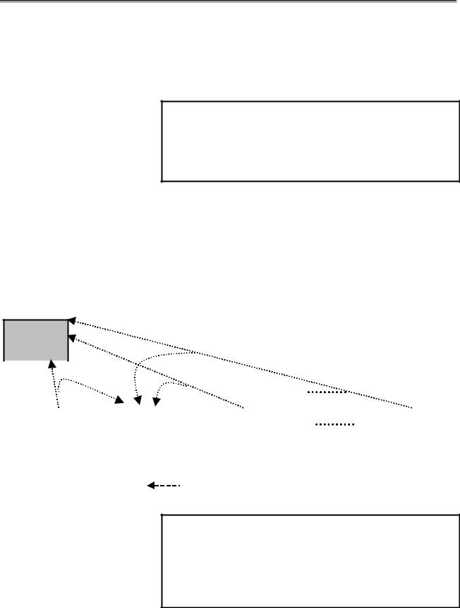
About the global I/O transfer function:
The figure below shows DI/DO data transfer performed between a master station and slave stations #1 to #N. Suppose that a slave station using the global I/O transfer function is a local slave station, and the other slave stations are remote slave stations. Then, the local slave station (#2) can receive DO data sent from the master station and can also receive DO data sent to the master station from the remote slave stations. So, the local slave station can make a ladder reference.
Master
station
|
|
|
|
|
|
|
|
|
|
|
|
|
|
|
|
|
|
|
|
|
|
|
|
|
|
|
|
|
|
|
|
|
|
Slave station #1 |
|
Slave station #2 |
|
Slave station #3 |
|
|
|
Slave station #N |
||||||||
[Remote slave |
|
[Local slave |
|
[Remote slave |
|
|
|
[Remote slave |
||||||||
|
station] |
|
|
station] |
|
|
station] |
|
|
|
station] |
|||||
|
|
|
|
|
|
|
|
|
|
|
|
|
|
|
|
|
DO data from slave stations #1 to #N (excluding #2)
NOTE
The global I/O transfer function is not a function defined by OPCN-1 but a FANUC unique function. This function can be used even when the network includes products of other manufacturers (even as a master station). In this case, however, the size of data that can be transferred is limited.
- 12 -

B-62714EN/04 SPECIFICATIONS 1.I/O LINK-II I/O FUNCTION
|
1.4 |
SPECIFICATIONS |
|
|
|
|
|
|
|
|
|
|
|
|
Type |
|
Master station |
Master station |
Slave station |
|
|
Applicable CNC |
|
16/18/21-B, 16/18-C |
LCD-mounted type |
16/18/21-B, 16/18-C |
|
|
|
16i/18i/21i-A/B |
|
|||
|
|
|
|
|
|
|
|
Board (printed circuit board |
I/O Link-II board |
I/O Link-II board |
I I/O Link-II board |
|
|
|
drawing number) |
|
A16B-2202-0152 |
A20B-8100-0250 |
A16B-2202-0152 |
|
|
Control software |
|
6546 series |
6546 series |
6545 series |
|
|
Maximum DI/DO size of the |
62 bytes/62 bytes (16/18-C) |
|
62 bytes/62 bytes (16/18-C) |
|
|
|
32 bytes/32 bytes |
128 bytes/128 bytes |
|
|||
|
DI/DO data transfer function |
32 bytes/32 bytes (16/18/21-B) |
|
|||
|
(16/18/21-B) |
|
|
|||
|
|
|
|
|
|
|
|
Maximum DI/DO size of the |
--- |
--- |
48 bytes |
|
|
|
global I/O transfer function |
|
||||
|
|
|
|
|
||
|
DI/DO allocatable area of |
|
R0000-R0999 for both |
|
|
|
|
|
DI and DO |
|
|
||
|
the DI/DO data transfer |
R0000-R0999 for both DI |
R0000-R0999 for both DI and |
|
||
|
(PMC-SA1/SA5) |
|
||||
|
function |
|
and DO |
DO |
|
|
|
|
R0000-R1499 for both |
|
|||
|
|
|
(PMC-SA1/SA3) |
(PMC-SA1/SA3) |
|
|
|
DI/DO allocatable area of |
DI and DO |
|
|||
|
R0000-R1499 for both DI |
R0000-R1499 for both DI and |
|
|||
|
(PMC-SB5) |
|
||||
|
the global I/O transfer |
and DO |
DO |
|
||
|
R0000-R2999 for both |
|
||||
|
function |
|
(PMC-SB3/SC3/SB5) |
(PMC-SB3/SC3/SB5) |
|
|
|
|
DI and DO |
|
|||
|
|
|
R0000-R2999 for both DI |
R0000-R2999 for both DI and |
|
|
|
|
|
(PMC-SB6) |
|
||
|
|
|
and DO |
DO |
|
|
|
Status information |
R0000-R7999 for both |
|
|||
|
(PMC-SB4/SC4/SB6) |
(PMC-SB4/SC4/SB6) |
|
|||
|
allocatable area |
|
DI and DO |
|
||
|
|
|
|
|
||
|
|
|
|
(PMC-SB7) |
|
|
|
|
|
I,II |
I,II |
I,II |
|
|
Reference items of this |
III-1.1,III-1.3 |
III-1.1, III-1.3 |
III-1.2, III-1.3 |
|
|
|
manual |
|
IV-1,IV-2 |
IV-1,IV-3 |
IV-1,IV-2 |
|
|
|
|
V-1 |
V-2 |
V-1 |
|
|
JEMA net |
|
--- |
--- |
--- |
|
- 13 -
1.I/O LINK-II I/O FUNCTION |
SPECIFICATIONS |
B-62714EN/04 |
|||||
|
|
|
|
|
|
||
|
Type |
Master station |
Master station |
Slave station |
|||
Applicable CNC |
LCD-mounted type |
|
PM-D/F/H |
PMi-D/H |
|||
16i/18i/21i-A/B |
|
||||||
|
|
|
|
|
|
||
Board (printed circuit board |
I/O Link-II board |
|
I/O Link-II board |
I/O Link-II board |
|||
drawing number) |
A20B-8100-0250 |
|
A20B-2100-0041, 0040 |
A20B-8100-0310 |
|||
Control software |
6545 series |
|
8816 series |
8816 series |
|||
Maximum DI/DO size of the |
128 bytes/128 bytes |
32 bytes/32 bytes (PM-F/H) |
32 bytes.32 bytes |
||||
DI/DO data transfer function |
64 bytes/64 bytes (PM-D) |
||||||
|
|
|
|
||||
Maximum DI/DO size of the |
48 bytes |
|
48 bytes(Caution) |
48 bytes(Caution) |
|||
global I/O transfer function |
|
||||||
|
|
|
|
|
|||
DI/DO allocatable area of |
R0000-R0999 for both DI |
DI : X1002-X1063 |
DI : X1032-X1063 |
||||
and DO |
|
||||||
the DI/DO data transfer |
|
DO : Y1002-Y1063 |
DO : Y1032-Y1063 |
||||
(PMC-SA1/SA5) |
|
||||||
function |
|
(PMC-PA1/PA3) |
(PMC-SB5/SB6) |
||||
R0000-R1499 for both DI |
|||||||
|
|
|
|
|
|||
DI/DO allocatable area of |
and DO |
|
|
|
|
||
(PMC-SB5) |
|
|
|
|
|||
the global I/O transfer |
|
|
|
|
|||
R0000-R2999 for both DI |
|
|
|
||||
function |
R0000-R0999 for both DI |
R0000-R0999 for both DI |
|||||
and DO |
|
||||||
|
|
|
and DO |
and DO |
|||
|
|
(PMC-SB6) |
|
||||
|
|
|
(PMC-PA1/PA3) |
(PMC-SB5/SB6) |
|||
Status information |
R0000-R7999 for both DI |
||||||
|
|
|
|||||
allocatable area |
and DO |
|
|
|
|
||
|
|
(PMC-SB7) |
|
|
|
|
|
|
|
I,II |
|
I,II |
I,II |
||
Reference items of this |
III-1.2,III-1.3 |
|
III-3.1,III-3.2 |
III-3.1,III-3.2 |
|||
manual |
IV-1,IV-3 |
|
IV-1,IV-5 |
IV-1,IV-6.1, IV-6.2, IV-6.3 |
|||
|
|
V-2 |
|
V-4 |
V-5.1 |
||
JEMA net |
--- |
|
--- |
--- |
|
||
- 14 -

B-62714EN/04 |
SPECIFICATIONS |
1.I/O LINK-II I/O FUNCTION |
|||||
|
|
|
|
|
|
|
|
|
Type |
Master station |
Slave station |
|
Slave station |
||
Applicable CNC |
Stand-alone type |
Stand-alone type |
|
PMi-D/H |
|||
16i/18i/21i-A |
16i/18i/21i-A |
|
|||||
|
|
|
|
|
|||
|
|
I/O Link-II board B1 |
I/O Link-II board B1 |
|
I/O Link-II board B |
||
Board (printed circuit board |
A20B-8100-0380 |
A20B-8100-0380 |
|
||||
drawing number) |
I/O Link-II board B2 |
I/O Link-II board B2 |
|
A20B-8100-0381 |
|||
|
|
A20B-8100-0381 |
A20B-8100-0381 |
|
|
|
|
Control software |
654B series |
654A series |
|
654A series |
|||
Maximum DI/DO size of the |
128 bytes/128 bytes |
128 bytes/128 bytes |
|
128 bytes/128 bytes |
|||
DI/DO data transfer function |
|
||||||
|
|
|
|
|
|||
Maximum DI/DO size of the |
--- |
48 bytes |
|
48 bytes |
|||
global I/O transfer function |
|
||||||
|
|
|
|
|
|||
DI/DO allocatable area of |
R0000-R0999 for both DI |
R0000-R0999 for both DI |
|
|
|||
the DI/DO data transfer |
and DO |
and DO |
|
R0000-R1499 for both DI |
|||
function |
(PMC-SA1/SA5) |
(PMC-SA1/SA5) |
|
||||
|
and DO |
||||||
DI/DO allocatable area of |
R0000-R1499 for both DI |
R0000-R1499 for both DI |
|||||
(PMC-SB5) |
|||||||
the global I/O transfer |
and DO |
and DO |
|
||||
|
R0000-R2999 for both DI |
||||||
function |
(PMC-SB5) |
(PMC-SB5) |
|
||||
|
and DO |
||||||
|
|
R0000-R2999 for both DI |
R0000-R2999 for both DI |
||||
Status information |
(PMC-SB6) |
||||||
and DO |
and DO |
|
|||||
allocatable area |
|
|
|
||||
(PMC-SB6) |
(PMC-SB6) |
|
|
|
|||
|
|
|
|
|
|||
|
|
I,II |
I,II |
|
I,II |
||
Reference items of this |
III-2.1,III-2.3 |
III-2.2,III-2.3 |
|
III-2.2,III-2.3 |
|||
manual |
IV-1,IV-4 |
IV-1,IV-4 |
|
IV-1, IV-6.1, IV-6.2, IV-6.4 |
|||
|
|
V-3 |
V-3 |
|
V-5.2 |
||
JEMA net |
OPCN-1 certified device |
OPCN-1 certified device |
OPCN-1 certified device |
||||
CAUTION
The I/O Link-II board (A20B-2100-041) for PM-D/H and the I/O Link-II board (A20B-8100-0310) for PMi-
D/H cannot use the global I/O transfer function because of a mixture with the other stations (master station and slave stations) using I/O Link-II boards B, B1, and B2.
- 15 -

1.I/O LINK-II I/O FUNCTION |
SPECIFICATIONS |
B-62714EN/04 |
1.5 GLOSSARY
Key terms used this manual are explained below.
OPCN-1 (formerly called JPCN-1 or JEMA net)
Field network defined by the Japan Electrical Manufacturer's Association
OPCN-1 certified device
FANUC device that passed the OPCN-1 certification test Certification number: J990705JPCNM026
Date of certification: July 5, 1999
Master station
Station that establishes and cancels logical communication paths to multiple slave stations, manages the data transmission service issue sequence and error recovery sequence, and performs I/O transfer. One OPCN-1 network can include only one master station.
Slave station
Station that exercises communication control and performs I/O transfer to and from the master station according to instructions from the master station. One OPCN-1 network can include up to 31 slave stations.
Initialization service
Service defined by OPCN-1 for information exchange and setting to establish logical communication paths between the master station and slave stations. When the initialization service is executed successfully, input/output service can be started.
Input/output service
Service defined by OPCN-1 for DI/DO data transfer between the master station and slave stations
Reset service
Service defined by OPCN-1 for the master station to reset slave stations to the initial state
Initial state
State where no logical communication path is established
Detachment
State where communication (input/output service being performed) with the remote station is disabled
Disconnection
State where communication is not performed (such as in the initial state or detached state)
- 16 -

B-62714EN/04 |
SPECIFICATIONS |
1.I/O LINK-II I/O FUNCTION |
DI data
Input data when viewed from the local station (master station or slave station)(Caution)
DO data
Output data when viewed from the local station (master station or slave station)(Caution)
CAUTION
In the OPCN-1 specifications, data input/output is defined as data input/output viewed from the master station. Note that the use of the term in this manual for slave stations is opposite to the definition in the OPCN-1 specifications.
For communication with devices of other manufacturers, check the definition of data input/output.
DI/DO data transfer function
Function for exchanging DI/DO data between the master station and slave stations of I/O Link-II. This function is implemented by input/output service of OPCN-1.
Global I/O transfer function
FANUC unique function. When DI/DO data is exchanged between the master station and multiple slave stations, a slave station receives DO data sent from the other slave stations to the master station, thus achieving I/O transfer between the slave stations.
Successive error detach detection counter
Maximum allowable number of successive communication errors. When this maximum number is exceeded, a detachment is detected.
One scan
Executing input/output service once for all slave stations connected to the network
Slave type
Initialization service parameter defined by OPCN-1 for determining the type of communication between the master station and slave stations
- 17 -

1.I/O LINK-II I/O FUNCTION SPECIFICATIONS B-62714EN/04
stypeM
Slave type set by the master station
|
stypeM |
|
bit 7 |
bit 6 |
bit 5 |
|
bit 4 |
bit 3 |
bit 2 |
bit 1 |
bit 0 |
|
Bits 7 and 6 |
: |
Reserved (0 at all times) |
|
|
|
|
|
|
||||
|
Bit 5 |
: |
SA (whether information and I/O from the master station to a slave |
|||||||||
|
|
|
station are specified) |
|
|
|
|
|
|
|||
-When SA = 0, information and I/O from the master station to a slave station are not specified.
-When SA = 1, information and I/O from the master station to a slave station are specified
Bit 4 : ST (whether a type of I/O from the master station to a slave station is specified)
-When ST = 0, no type of I/O from the master station to a slave station is specified.
-When ST = 0, a type of I/O from the master station to a slave station is specified.
NOTE
The setting of bits 3 to 1 is valid when ST = 1.
Bit 3 : DW (data write)
Set DW = 1 to enable data write service.
Bit 2 : DR (data read)
Set DR = 1 to enable data read service.
Bit 1 : DO (output)
Set DO = 1 to perform input/output service and enable output.
Bit 0 : DI (input)
Set DI = 1 to perform input/output service and enable input.
stypeS
Slave type set by a slave station
stypeS |
|
bit 7 |
bit 6 |
bit 5 |
bit 4 |
bit 3 |
bit 2 |
bit 1 |
bit 0 |
Bits 7 to 4 : Reserved (0 at all times) Bit 3 : DW (data write)
Set DW = 1 to enable data write service. Bit 2 : DR (data read)
Set DR = 1 to enable data read service.
Bit 1 : DO (output from the master station) when viewed from the master station
Set DO = 1 to perform input/output service and enable output.
Bit 0 : DI (input to the master station) when viewed from the master station Set DI = 1 to perform input/output service and enable input.
- 18 -
III. OPERATION

B-62714EN/04 OPERATION 1.16/18/21-B, 16/18-C, LCD-MOUNTED TYPE 16i/18i/21i-A/B
1 16/18/21-B, 16/18-C, LCD-MOUNTED TYPE 16i/18i/21i-A/B
This chapter describes the setting procedure for operating the master function and slave function.
NOTE
The parameters related to the I/O Link-II function are stored in the SRAM on an I/O Link-II board. When using an I/O Link-II board for the first time, initialize the SRAM on the board according to Section 1.3, "SETTING" of Part V, "MAINTENANCE" (for 16/18/21-B and 16/18-C) or Section 2.3 "SETTING" of the same part (for 16i/18i/21i-A/B).
- 21 -

1.16/18/21-B, 16/18-C, LCD-MOUNTED TYPE 16i/18i/21i-A/B OPERATION |
B-62714EN/04 |
1.1 MASTER FUNCTION
Display of the setting screen
Procedure
(1)Press the function key SYSTEM, then select the soft key [PMC] to switch to the PMC screen.
(2)Select the soft keys [PMCDGN], [I/OCHK], and [IOLNK2] in this order. Screen 1-1 appears.
Screen 1-1
- 22 -

B-62714EN/04 OPERATION 1.16/18/21-B, 16/18-C, LCD-MOUNTED TYPE 16i/18i/21i-A/B
Setting items and display items
Setting items
|
Table III-1-1 |
|
Item |
Description |
|
|
Maximum slave station number used for |
|
MAX SLAVE NO. |
communication with the master station. |
|
|
Setting range: 1 to 31 |
|
|
Interval for performing one scan of input/output |
|
|
service. |
|
|
Set a value greater than the value of REFRESH |
|
|
TIME. |
|
|
Guideline for setting: |
|
SCAN TIME |
SCAN TIME = MAX SLAVE NO. × 2 + 2 |
|
|
Setting unit: 2 msec |
|
|
Setting range: 1 to 9999 |
|
|
Example of setting: |
|
|
When 4 is set in SCAN TIME, the setting of 8 msec |
|
|
is assumed. |
|
|
Start address of an area for storing communication |
|
STATUS ADDRESS |
status. |
|
|
Setting range: R area of the PMC |
|
|
Slave station communication monitoring time |
|
OPTION1 |
Recommended setting: 14 [hexadecimal] →40 msec |
|
Setting unit: msec |
||
|
||
|
Setting range: 03 to D0 (hexadecimal) |
|
|
Successive error detach detection counter. |
|
|
Recommended setting: 3 [hexadecimal] |
|
OPTION2 |
Setting range: 00 to FF (hexadecimal) |
|
|
When the default value 0 is used, the setting of 3 is |
|
|
assumed for operation. |
|
|
Determines the method of allocating a DI/DO data |
|
|
area. |
|
|
Setting: 1, 2 |
|
DI/DO MAP MODE |
1: A DI data area and DO data area are allocated for |
|
the number of stations set in MAX SLAVE NO.. |
||
|
||
|
2: A DI data area is allocated for the number of |
|
|
stations set in MAX SLAVE NO., and a DO data |
|
|
area is allocated for one station. |
|
|
DI/DO data area size. |
|
|
Setting range: 0 to 62 (16/18/21-B, 16/18-C) |
|
DI/DO DATA SIZE |
Setting range: 0 to 128 (LCD-mounted type |
|
|
16i/18i/21i-A) |
|
|
(Unit: Bytes) |
|
DO ADDRESS |
DO data area start address. |
|
Setting range: R area of the PMC |
||
|
||
DI ADDRESS |
DI data area start address. |
|
Setting range: R area of the PMC |
||
|
||
MESSAGE SIZE |
Not used |
|
OUTPUT ADDRESS |
Not used |
|
INPUT ADDRESS |
Not used |
- 23 -

1.16/18/21-B, 16/18-C, LCD-MOUNTED TYPE 16i/18i/21i-A/B OPERATION |
B-62714EN/04 |
NOTE
The baud rate cannot be changed, but is fixed at 1
Mbps.
Display items
|
Table III-1-1 |
|
Item |
Description |
|
|
Interval at which DI data from all slave stations set in |
|
REFRESH TIME. |
MAX SLAVE NO. is reflected in the R area of the PMC. |
|
|
Unit: 1 msec |
|
I/O LINK-II |
The series and edition of the EPROM installed on the |
|
I/O Link-II board are displayed. |
||
|
- 24 -
 Loading...