


FANUC I/O Unit-MODEL A
CONNECTION AND MAINTENANCE MANUAL
B-61813E/04

•No part of this manual may be reproduced in any form.
•All specifications and designs are subject to change without notice.
In this manual we have tried as much as possible to describe all the various matters. However, we cannot describe all the matters which must not be done, or which cannot be done, because there are so many possibilities.
Therefore, matters which are not especially described as possible in this manual should be regarded as ”impossible”.
This manual contains the program names or device names of other companies, some of which are registered trademarks of respective owners. However, these names are not followed by or in the main body.

B-61813E/04 |
DEFINITION OF WARNING, CAUTION, AND NOTE |
DEFINITION OF WARNING, CAUTION, AND NOTE
This manual includes safety precautions for protecting the user and preventing damage to the machine. Precautions are classified into Warning and Caution according to their bearing on safety. Also, supplementary information is described as a Note. Read the Warning, Caution, and Note thoroughly before attempting to use the machine.
 WARNING
Applied when there is a danger of the user being injured or when there is a damage of both the user being injured and the equipment being damaged if the approved procedure is not observed.
 CAUTION
Applied when there is a danger of the equipment being damaged, if the approved procedure is not observed.
NOTE
The Note is used to indicate supplementary information other than Warning and Caution.
- Read this manual carefully, and store it in a safe place.
s-1

B-61813E/04 |
PREFACE |
PREFACE
Applicable models
This manual describe the following products:
|
Name of products |
Abbreviation |
|
FANUC I/O Unit-MODEL A |
I/O Unit-A |
Applicable CNCs |
|
|
Name of products |
Abbreviation |
|
FANUC Power Mate |
Power Mate |
|
FANUC Series 0 (MODEL C) |
Series 0-C |
|
FANUC Series 15 |
Series 15 |
|
FANUC Series 16 |
Series 16 |
|
FANUC Series 18 |
Series 18 |
|
FANUC Series 20 |
Series 20 |
|
FANUC Series 21 |
Series 21 |
|
FANUC SYSTEM F-MODEL D Mate |
F-D Mate |
|
FANUC Power Mate i |
Power Mate i |
|
FANUC Series 0i |
Series 0i |
|
FANUC Series 15i |
Series 15i |
|
FANUC Series 16i |
Series 16i |
|
FANUC Series 18i |
Series 18i |
|
FANUC Series 20i |
Series 20i |
|
FANUC Series 21i |
Series 21i |
|
FANUC Series 30i |
Series 30i |
|
FANUC Series 31i |
Series 31i |
|
FANUC Series 32i |
Series 32i |
|
|
|
|
Other related models |
|
|
|
Name of products |
Abbreviation |
|
FANUC I/O Unit-MODEL B |
I/O Unit-B |
Abbreviations of manufacturer names used herein |
|
|
This manual uses the following abbreviations for manufacturers of products such as connectors.
Manufacturer name |
Abbreviation |
Daito Communication Apparatus Co., Ltd. |
Daito |
Fujitsu Limited |
Fujitsu |
HIROSE ELECTRIC CO., LTD. |
HIROSE ELECTRIC |
HONDA TSUSHIN KOGYO CO., LTD. |
HONDA TSUSHIN |
Molex Incorporated |
Molex |
Nihon Weidmüller Co., Ltd. |
Weidmüller |
SORIAU JAPAN |
SORIAU JAPAN |
Tyco Electronics AMP K.K. |
Tyco Electronics |
p-1

B-61813E/04 |
TABLE OF CONTENTS |
TABLE OF CONTENTS
DEFINITION OF WARNING, CAUTION, AND NOTE ................................. |
s-1 |
|||
PREFACE |
.................................................................................................... |
|
p-1 |
|
I. CONNECTION |
|
|||
1 |
FANUC I/O Link ...................................................................................... |
3 |
||
|
1.1 |
CONFIGURATION......................................................................................... |
4 |
|
|
1.2 |
ALLOCATION OF I/O POINTS...................................................................... |
5 |
|
2 |
I/O Unit CONFIGURATION..................................................................... |
7 |
||
3 |
INSTALLATION ...................................................................................... |
8 |
||
|
3.1 |
ENVIRONMENT FOR INSTALLATION ......................................................... |
9 |
|
|
|
3.1.1 Environmental Conditions outside the Cabinet........................................................ |
9 |
|
|
3.2 |
DESIGNING CONDITION FOR A CABINET ............................................... |
10 |
|
|
3.3 |
OUTER DIMENSION OF I/O Unit................................................................ |
11 |
|
|
3.4 |
MOUNTING AND DISMOUNTING MODULES............................................ |
15 |
|
4 |
CONNECTION....................................................................................... |
16 |
||
|
4.1 |
GENERAL CONNECTION DIAGRAM......................................................... |
17 |
|
|
4.2 |
CONNECTING INPUT POWER SOURCE .................................................. |
18 |
|
|
4.3 |
GROUNDING .............................................................................................. |
19 |
|
|
4.4 |
REQUIRED CURRENT ............................................................................... |
20 |
|
|
4.5 |
INTERFACE MODULE (AIF01A, AIF01A2, AIF01B) ................................... |
21 |
|
|
4.6 |
INTERFACE MODULE (AIF02C) CONNECTION........................................ |
24 |
|
|
|
4.6.1 |
Overview ................................................................................................................ |
24 |
|
|
4.6.2 |
Connection ............................................................................................................. |
25 |
|
|
4.6.3 Setting with the DIP Switch ................................................................................... |
27 |
|
|
4.7 |
CONNECTING WITH I/O MODULES .......................................................... |
28 |
|
5 |
DIGITAL INPUT/OUTPUT MODULES .................................................. |
30 |
||
|
5.1 |
LIST OF MODULES .................................................................................... |
31 |
|
5.2CORRESPONDENCE BETWEEN I/O SIGNALS AND ADDRESSES IN A
|
MODULE ..................................................................................................... |
34 |
|
|
5.2.1 Module with 16/32 Digital Inputs (DI) .................................................................. |
34 |
|
|
5.2.2 |
Module with 5/8/12/16/32 Digital Outputs (DO)................................................... |
34 |
|
5.2.3 |
AIO40A Module (Hybrid Module with 24 Input and 16 Output Points)............... |
35 |
5.3 |
SPECIFICATION FOR EACH MODULE ..................................................... |
36 |
|
c-1
TABLE OF CONTENTS |
B-61813E/04 |
5.4DETAILS OF I/O Unit CONNECTORS (HONDA TSUSHIN/HIROSE
ELECTRIC) AND TERMINAL BLOCK (WEIDMÜLLER).............................. |
74 |
5.4.1 Modules Using the MR-50RMA Connector Manufactured by Honda Tsushin..... |
75 |
5.4.2 Modules Using the HIF3BB-50PA-2.54DS Connector Manufactured by |
|
Hirose Electric........................................................................................................ |
77 |
5.4.3 Modules Using the HIF4-40P-3.18DS Connector Manufactured by |
|
Hirose Electric........................................................................................................ |
79 |
5.4.4 Modules Using the Terminal Block BL3.5/24/90F Manufactured by |
|
Weidmüller............................................................................................................. |
80 |
6 ANALOG INPUT MODULE................................................................... |
81 |
||
6.1 |
12-BIT ANALOG INPUT MODULE (AAD04A)............................................. |
82 |
|
|
6.1.1 |
Specifications ......................................................................................................... |
82 |
|
6.1.2 Correspondence between Input Signals and Addresses in a Module ..................... |
83 |
|
|
6.1.3 Connecting with Analog Input Module.................................................................. |
85 |
|
6.2 |
16-BIT ANALOG INPUT MODULE (AAD04B)............................................. |
86 |
|
|
6.2.1 |
Specifications ......................................................................................................... |
86 |
|
6.2.2 Correspondence between Input Signals and Addresses in a Module ..................... |
87 |
|
|
6.2.3 Connecting with Analog Input Module.................................................................. |
89 |
|
7 ANALOG OUTPUT MODULE............................................................... |
90 |
||
7.1 |
12-BIT ANALOG OUTPUT MODULE (ADA02A)......................................... |
91 |
|
|
7.1.1 |
Specification........................................................................................................... |
91 |
|
7.1.2 Correspondence between Output Signals and Addresses in a Module .................. |
92 |
|
|
7.1.3 Connection to Analog Output Module ................................................................... |
93 |
|
7.2 |
14-BIT ANALOG OUTPUT MODULE (ADA02B)......................................... |
94 |
|
|
7.2.1 |
Specification........................................................................................................... |
94 |
|
7.2.2 Correspondence between Output Signals and Addresses in the Module ............... |
95 |
|
|
7.2.3 Connection between the Analog Output Module and Load ................................... |
96 |
|
8 HIGH-SPEED COUNTER MODULE ..................................................... |
97 |
||
8.1 |
OUTLINE OF HIGH-SPEED COUNTER MODULE ..................................... |
98 |
|
8.2 |
SPECIFICATIONS OF HIGH-SPEED COUNTER MODULE..................... |
100 |
|
|
8.2.1 |
Pulse Counter ....................................................................................................... |
100 |
|
8.2.2 |
Comparison Function ........................................................................................... |
100 |
|
8.2.3 |
Pulse Interface ...................................................................................................... |
102 |
|
8.2.4 |
External Contact Input.......................................................................................... |
105 |
|
8.2.5 |
External Contact Output....................................................................................... |
105 |
|
8.2.6 |
Marker Processing................................................................................................ |
106 |
|
|
c-2 |
|
B-61813E/04 |
|
TABLE OF CONTENTS |
|
|
8.2.7 |
LED indicators ..................................................................................................... |
107 |
8.3 |
PMC INTERFACE ..................................................................................... |
109 |
|
|
8.3.1 |
Mode A................................................................................................................. |
109 |
|
8.3.2 |
Mode B................................................................................................................. |
111 |
|
8.3.3 Details of PMC Interface Signals ......................................................................... |
114 |
|
8.4 |
TOTAL CONNECTION OF HIGH-SPEED COUNTER MODULE .............. |
117 |
|
|
8.4.1 |
Connection Diagram............................................................................................. |
117 |
|
8.4.2 |
Connector Signal List........................................................................................... |
117 |
|
|
8.4.2.1 C49 signal (for mode A).................................................................................. |
118 |
|
|
8.4.2.2 C49 signal (for mode B) .................................................................................. |
118 |
8.5 |
CONNECTION WITH PULSE GENERATOR ............................................ |
119 |
|
|
8.5.1 Use of Phase A and B Pulses................................................................................ |
119 |
|
|
8.5.2 Use of Positive/Negative Pulses........................................................................... |
120 |
|
8.6 |
CONNECTION WITH MACHINE (POWER MAGNETICS CABINET) ....... |
121 |
|
|
8.6.1 Use in Mode A ..................................................................................................... |
121 |
|
|
8.6.2 Use in Mode B...................................................................................................... |
122 |
|
8.7 |
I/O SIGNALS CONVENTIONS .................................................................. |
123 |
|
|
8.7.1 Solid State Relay Output Signals (OUT0 to OUT7) ............................................ |
123 |
|
|
8.7.2 DC Input Signals (ME and CSP).......................................................................... |
124 |
|
|
8.7.3 +5-V Output from JA9 Connector........................................................................ |
124 |
|
8.8 |
SUPPLEMENT .......................................................................................... |
125 |
|
|
8.8.1 Configuration of Mode A..................................................................................... |
125 |
|
|
8.8.2 Counter Presetting and Counting ......................................................................... |
126 |
|
|
8.8.3 |
Setting Data .......................................................................................................... |
129 |
|
8.8.4 |
Reading Data ........................................................................................................ |
130 |
8.9 |
EXAMPLE OF STARTING UP ACT01A .................................................... |
131 |
|
|
8.9.1 Mode A Startup Flowchart ................................................................................... |
131 |
|
|
8.9.2 Example of Mode A Ladder................................................................................. |
132 |
|
|
8.9.3 Mode B Startup Flowchart ................................................................................... |
136 |
|
|
8.9.4 Example of Mode B Ladder ................................................................................. |
137 |
|
9 TEMPERATURE INPUT MODULE ..................................................... |
144 |
||
9.1 |
OVERVIEW ............................................................................................... |
145 |
|
9.2 |
TEMPERATURE INPUT MODULE SPECIFICATION ............................... |
146 |
|
9.3 |
PMC INTERFACE ..................................................................................... |
147 |
|
|
9.3.1 |
PMC I/O Area ...................................................................................................... |
147 |
|
9.3.2 |
Measurement Mode.............................................................................................. |
148 |
|
9.3.3 Details of Output Signals (PMC → Temperature Module).................................. |
148 |
|
|
|
c-3 |
|
TABLE OF CONTENTS |
B-61813E/04 |
||
|
9.3.4 |
Details of Input Signals (Temperature Module → PMC) .................................... |
151 |
9.4 |
COMPLETE CONNECTION OF TEMPERATURE INPUT MODULE ........ |
154 |
|
|
9.4.1 |
Temperature Input Module Connection Diagram ................................................ |
154 |
|
9.4.2 |
Connector Signal Lists ......................................................................................... |
155 |
|
9.4.3 |
Terminal Board Unit Connection Diagram .......................................................... |
156 |
9.5 |
TIMING CHARTS ...................................................................................... |
157 |
|
9.6 |
MEASUREMENT EXAMPLES................................................................... |
158 |
|
9.7 |
TERMINAL BOARD UNIT DIMENSIONS.................................................. |
165 |
|
10 OPTICAL I/O Link ADAPTER............................................................. |
166 |
||
10.1 |
EXTERNAL DIMENSION OF OPTICAL I/O Link....................................... |
167 |
|
10.2 |
WEIGHT OF OPTICAL I/O Link................................................................. |
167 |
|
10.3 |
CONNECTION OF OPTICAL I/O Link ....................................................... |
168 |
|
10.4 |
POWER SOURCE OF OPTICAL I/O Link ADAPTER ............................... |
169 |
|
10.5 |
INSTALLATION CONDITIONS OF OPTICAL I/O Link ADAPTER ............ |
169 |
|
10.6 |
CAUTIONS FOR USING OPTICAL I/O Link ADAPTERS ......................... |
170 |
|
|
10.6.1 |
Configuring I/O Links Using Optical I/O Link Adapters .................................... |
170 |
|
10.6.2 |
When Using Series 16i/18i/21i-MODEL B as Master ......................................... |
171 |
|
10.6.3 |
When Using Series 30i/31i/32i-MODEL B as Master ......................................... |
172 |
10.7 |
OPTICAL FIBER CABLE ........................................................................... |
174 |
|
|
10.7.1 |
External View of Optical Fiber Cable .................................................................. |
174 |
|
10.7.2 |
Notice of Optical Fiber Cable Handling............................................................... |
175 |
|
10.7.3 |
Optical Fiber Cable Clamping Method ................................................................ |
176 |
|
10.7.4 |
Relay Using an Optical Fiber Junction Adapter................................................... |
177 |
|
10.7.5 |
Maximum Transmission Distance by Optical Fiber Junction Cable .................... |
179 |
11 I/O Link DUMMY UNIT........................................................................ |
180 |
||
11.1 |
OVERVIEW ............................................................................................... |
181 |
|
11.2 |
EXTERNAL DIMENSIONS ........................................................................ |
181 |
|
11.3 |
LED INDICATORS..................................................................................... |
182 |
|
11.4 |
WEIGHT .................................................................................................... |
182 |
|
11.5 |
POWER REQUIREMENTS ....................................................................... |
182 |
|
11.6 |
INSTALLATION CONDITIONS.................................................................. |
182 |
|
11.7 |
CONNECTION DIAGRAMS....................................................................... |
183 |
|
|
11.7.1 |
When not Connecting FANUC I/O Link Dummy Units in Series ....................... |
183 |
|
11.7.2 |
Connecting FANUC I/O Link Dummy Units in Series........................................ |
184 |
|
11.7.3 |
Grounding............................................................................................................. |
184 |
|
11.7.4 |
K3X Cable............................................................................................................ |
185 |
|
|
c-4 |
|
B-61813E/04 |
|
TABLE OF CONTENTS |
|
12 TWO-CHANNEL I/O Link CONNECTOR ADAPTER |
......................... |
186 |
|
12.1 |
OVERVIEW ............................................................................................... |
|
187 |
12.2 |
CONNECTION FOR USE OF TWO FANUC I/O Link CHANNELS ........... |
187 |
|
12.3CONNECTING THE CNC WITH TWO-CHANNEL I/O Link CONNECTOR
ADAPTER.................................................................................................. |
188 |
12.4 CABLING................................................................................................... |
189 |
12.5CONNECTING TWO-CHANNEL I/O Link CONNECTOR ADAPTER TO
|
I/O Units FOR THE FANUC I/O Link ......................................................... |
189 |
12.6 |
CABLE LENGTH ....................................................................................... |
190 |
12.7 |
INSTALLING TWO-CHANNEL I/O Link CONNECTOR ADAPTER ........... |
190 |
12.8OUTSIDE DIMENSIONS OF TWO-CHANNEL I/O Link CONNECTOR
|
ADAPTER.................................................................................................. |
191 |
12.9 |
MOUNTING TWO-CHANNEL I/O Link CONNECTOR ADAPTER ............ |
192 |
13 THREE-CHANNEL I/O Link CONNECTOR ADAPTER ..................... |
193 |
|
13.1 |
OVERVIEW ............................................................................................... |
194 |
13.2 |
CONNECTION FOR USE OF FOUR FANUC I/O Link CHANNELS.......... |
194 |
13.3CONNECTING THE CNC WITH THREE-CHANNEL I/O Link
CONNECTOR ADAPTER.......................................................................... |
195 |
13.4 CABLING................................................................................................... |
195 |
13.5ALLOCATING THREE-CHANNEL I/O Link CONNECTOR ADAPTER
SIGNALS ................................................................................................... |
196 |
13.6CONNECTING THREE-CHANNEL I/O Link CONNECTOR ADAPTER
SIGNAL TO EACH CHANNEL................................................................... |
197 |
13.7CONNECTING THREE-CHANNEL I/O Link CONNECTOR ADAPTER
TO TWO-CHANNEL I/O Link CONNECTOR ADAPTER........................... |
199 |
13.8CONNECTING THREE-CHANNEL I/O Link CONNECTOR ADAPTER
|
TO I/O Units FOR THE FANUC I/O Link ................................................... |
200 |
13.9 |
CABLE LENGTH ....................................................................................... |
200 |
13.10 |
INSTALLING THREE-CHANNEL I/O Link CONNECTOR ADAPTER ....... |
200 |
13.11OUTSIDE DIMENSIONS OF THREE-CHANNEL I/O Link CONNECTOR
|
ADAPTER.................................................................................................. |
201 |
13.12 |
MOUNTING THREE-CHANNEL I/O Link CONNECTOR ADAPTER......... |
202 |
14 SAFETY FOR USING AC.................................................................... |
203 |
|
14.1 |
ENVIRONMENT FOR INSTALLATION ..................................................... |
204 |
|
14.1.1 Installation Category (Overvoltage Category) ..................................................... |
204 |
|
14.1.2 Pollution Degree................................................................................................... |
204 |
|
c-5 |
|
TABLE OF CONTENTS |
B-61813E/04 |
II. MAINTENANCE |
|
|
1 OVERVIEW ......................................................................................... |
207 |
|
1.1 |
SYSTEM CONFIGURATION..................................................................... |
208 |
1.2 |
I/O Unit-A CONFIGURATION.................................................................... |
209 |
1.3 |
BLOCK DIAGRAM..................................................................................... |
210 |
1.4 |
I/O Unit-MODEL A CONFORMING TO UL/C-UL ...................................... |
211 |
1.5 |
LIST OF UNITS ......................................................................................... |
212 |
|
1.5.1 Units Conforming to UL/C-UL Standard: Ordering Information |
|
|
A03B-0819-Jxxx .................................................................................................. |
212 |
|
1.5.2 Other Units (not Conforming to UL/C-UL) ......................................................... |
214 |
|
1.5.3 Early Units (Units not Conforming to UL/C-UL: Ordering Information |
|
|
A03B-0807-Jxxx)................................................................................................. |
214 |
2 |
INDICATION |
........................................................................................ |
|
|
216 |
|
|
2.1 |
INTERFACE MODULE (AIF01A, AIF01A2) LED INDICATORS ................ |
217 |
|||
|
2.2 |
INTERFACE MODULE (AIF01B) LED INDICATORS................................ |
220 |
|||
|
2.3 |
INTERFACE MODULE (AIF02C) LED INDICATORS................................ |
221 |
|||
|
|
2.3.1 |
PWR Indicator ...................................................................................................... |
221 |
||
|
|
2.3.2 |
LNK Indicators ..................................................................................................... |
221 |
||
|
|
2.3.3 |
ER Indicators ........................................................................................................ |
221 |
||
|
|
2.3.4 |
LED Indicators ..................................................................................................... |
221 |
||
|
|
2.3.5 |
|
|
Indicator |
222 |
|
|
M/S |
||||
|
|
2.3.6 |
No. Indicators ....................................................................................................... |
223 |
||
|
2.4 |
LED INDICATORS ON THE INPUT/OUTPUT MODULES (HAVING 16 |
|
|||
|
|
OR FEWER INPUT/OUTPUT POINTS) .................................................... |
223 |
|||
3 |
FUSES................................................................................................. |
|
|
|
224 |
|
4 |
REMOVING PC ...................................................................BOARDS |
225 |
||||
|
4.1 |
HOW TO REMOVE TERMINAL BOARD-TYPE I/O MODULE PC |
|
|||
|
|
BOARDS ................................................................................................... |
226 |
|||
4.2HOW TO REMOVE INTERFACE AND CONNECTOR-TYPE I/O
MODULE PC BOARDS ............................................................................. |
228 |
c-6
I. CONNECTION

B-61813E/04 |
CONNECTION |
1.FANUC I/O Link |
1 FANUC I/O Link
I/O Link is a serial interface with a purpose to transfer I/O signals (bit data) between CNC, cell controller, the I/O Unit-MODEL A, the Power Mate and so on at high-speed.
- 3 -

1.FANUC I/O Link |
CONNECTION |
B-61813E/04 |
1.1 |
CONFIGURATION |
|
|
|
|
|
|
|
|
|
|
|
|
|
|
|
|
|
|||
|
|
|
|
|
|
|
|
|
|
|
|
|
|
|
|
||||||
|
|
|
|
|
|
|
|
|
|
|
|
|
|
Slave |
|
||||||
|
|
|
|
|
|
|
|
|
|
|
|
|
|
|
|
|
|
|
|
|
|
|
|
CNC |
|
|
I/O Unit-A |
|
|
|
|
|
|
I/O Unit-A |
|||||||||
|
|
|
|
|
|
|
|
|
|
||||||||||||
|
|
Power Mate |
|
|
|
|
|
|
|
|
|
|
|
|
|
|
|
|
|
|
Group |
|
|
|
|
|
|
|
|
|
|
|
|
|
|
|
|
|
|
|
|
|
|
|
|
|
|
|
|
|
|
|
|
|
|
|
|
|
|
|
|
|
|
#0 |
|
|
|
|
|
|
|
|
|
|
|
|
|
|
|
|
|
|
|
|
|
|
|
|
|
|
|
|
|
|
|
|
|
|
|
|
|||||||||
|
|
|
|
|
Operator’s |
|
|
|
|
Group |
|||||||||||
|
|
|
|
|
panel |
|
|
|
#1 |
|
|
|
|
|
|
|
|||||
|
|
|
|
|
connection |
|
|
|
|
|
|
|
|
||||||||
|
|
|
|
|
|
|
|
|
|
|
|
|
|
|
|
|
|||||
|
|
|
|
|
unit |
|
|
|
|
|
|
|
|
|
|
|
|
||||
|
|
|
|
|
|
|
|
|
|
|
|
|
|
|
|
|
|
||||
|
|
|
|
|
Power Mate |
|
|
|
|
Group |
|||||||||||
|
|
|
|
|
|
|
|
|
|
|
|
|
|
||||||||
|
|
|
|
|
|
|
|
|
|
|
#2 |
|
|
|
|
|
|
|
|||
|
|
|
|
|
|
|
|
|
|
|
|
|
|
|
|
|
|
||||
|
|
|
|
|
|
|
|
|
|
|
|
|
|
|
|
|
|
||||
|
|
|
|
|
Series |
|
|
|
|
Group |
|||||||||||
|
|
|
|
|
0-C |
|
|
|
|
||||||||||||
|
|
|
|
|
|
|
|
#3 |
|
|
|
|
|
|
|
||||||
|
|
|
|
|
|
|
|
|
|
|
|
|
|
|
|
|
|
||||
|
|
|
|
|
|
|
|
|
|
|
|
|
|
|
|
|
|||||
|
|
|
|
|
|
|
|
|
|
|
|
|
|
|
|
|
|||||
|
: |
: |
|
|
|
: |
|
|
|
|
|
|
|
|
|
||||||
|
|
: |
: |
|
|
|
: |
|
|
|
|
|
|
|
|
|
|||||
|
|
: |
: |
|
|
|
: |
|
|
|
|
|
|
|
|
|
|
|
|||
|
|
|
|
|
|
|
|
|
|
|
|
|
|
|
|
|
|
|
|
|
|
|
|
|
|
|
Operator’s |
|
|
|
|
Group |
|||||||||||
|
|
|
|
|
panel |
|
|
|
|
||||||||||||
|
|
|
|
|
connection |
|
#15 |
|
|
|
|
|
|
|
|||||||
|
|
|
|
|
unit |
|
|
|
|
|
|
|
|
|
|
|
|
||||
(1)The FANUC I/O Link is made up of one master and a number of slaves.
Master:Series0-C, Series15/16/18/20/21, Series15i/16i/18i/20i/21i/30i/31i/32i/0i,
Power Mate-D/H, Power Mate i-D/H, F-D Mate
Slave: I/O Unit-A, I/O Unit-B, Operator's panel connection unit, Connector panel I/O module, Power Mate,
Series0-C, Servo unit β series (I/O Link option), and so on
(2) Up to 16 groups of slaves can be connected with a single I/O Link. Number of slaves per one group is as follows.
I/O Unit-A.............................................. |
Up to 2 units (i.e.2 bases) |
I/O Unit-B................................................................ |
Up to 30 units |
(Basic unit, basic and extension units). |
|
Operator's panel I/O module ................................................ |
1 unit |
(1 basic module and extension modules (up to three)
Operator's panel connection unit, connector panel I/O module, Power Mate, Series0-C, Servo unit β series (I/O Link option)
.............................................................................. 1 unit
(3)Any slave can be connected with any group. However, different types of slaves cannot be connected with a single group.
-4 -
B-61813E/04 |
CONNECTION |
1.FANUC I/O Link |
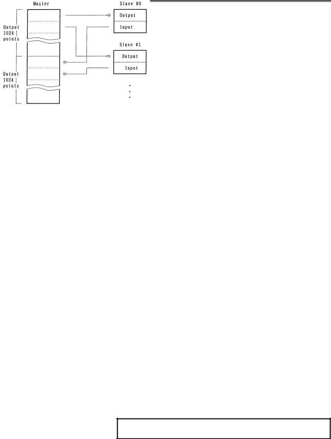
1.2 ALLOCATION OF I/O POINTS
I/O Link has 1024 input points per 1 channel and 1024 output points per 1 channel as viewed from the master.
I/O data is periodically transferred between the master and slaves by allotting these I/O points to each slave.
Each slave can occupy as many I/O points as determined for it. For the I/O Link, the total number of I/O points occupied by all slaves per channel must meet:
Number of input points ≤ 1024 Number of output points ≤ 1024
Number of actual I/O points may differ from that of the occupied ones. How to determine the number of I/O points to be allotted to each slave and restrictions for allocation are shown in the followings.
(For the allocation method for I/O points, refer to the PMC PROGRAMMING MANUAL.)
(1)Sum the numbers of the I/O points for all slaves connected with a single I/O Link. The sum must satisfy the following restriction :
Number of input points ≤ 1024 (per one I/O Link)
Number of output points ≤ 1024 (per one I/O Link)
(2)Number of the occupied I/O points per one group must satisfy the following restriction :
Number of input points ≤ 256 (per one group)
Number of output points ≤ 256 (per one group)
(3)Determine the number of I/O points for the I/O Unit-A using the following.
[Output points] |
|
|
Sum of the actual output |
Occupied output |
|
points in a group |
|
points |
0 to 32 |
32 points |
|
40 to 64 |
|
64 points |
72 to 128 |
|
128 points |
136 to 256 |
|
256 points |
NOTE
Count AOA05E as 8 points AOA12F as 16 points.
- 5 -
1.FANUC I/O Link |
CONNECTION |
|
|
|
B-61813E/04 |
|
|
[Input points] |
|
|
|
|
|
|
Sum of the actual output |
|
Occupied output |
|||
|
points in a group |
|
|
points |
|
|
|
0 to 32 |
|
|
32 points |
|
|
|
40 to 64 |
|
|
|
64 points |
|
|
72 to 128 |
|
|
|
128 points |
|
|
136 to 256 |
|
|
256 points |
||
|
However, as result of the calculation above, when the number of |
|||||
|
input points is not larger than that of the output points in a single |
|||||
|
group, the number of input points is assumed to be equal to that of |
|||||
|
the output points. |
|
|
|
|
|
|
Example 1 : When the following modules are used in the group |
|||||
|
|
No. 0. |
|
|
|
|
|
|
AOD32C |
3 |
AID32A |
5 |
|
|
|
AOA12F |
2 |
AIA16G |
3 |
|
|
|
[Output points] |
|
|
||
|
|
32 3 + 16 2 = 128 128 points |
||||
|
|
[Input points] |
|
|
||
|
|
32 5 + 16 3 = 208 256 points |
||||
|
Example 2: |
When the following modules are used in the group |
||||
|
|
No.2 |
|
|
|
|
|
|
AOD16C |
7 |
AID16C |
4 |
|
|
|
AOA05E |
9 |
AIA16G |
3 |
|
|
|
[Output points] |
|
|
||
|
|
16 7 + 8 9 = 184 256 points |
||||
[Input points]
16 4 + 16 3 = 112 128 points
In this case, as the number of input points is not larger than that of the output points, the number of input points is assumed to be equal to that of the output points, in other words, 256 points.
- 6 -
B-61813E/04 |
CONNECTION |
2.I/O Unit CONFIGURATION |
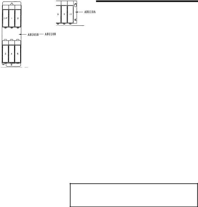
2 I/O Unit CONFIGURATION
5-slot horizontal base unit (ABU05A)
10-slot horizontal base unit (ABU10A)
5-slot vertical base unit (ABU05B)
10-slot vertical base unit (ABU10B)
NOTE
I/F : Interface module (AIF01A, AIF01A2, AIF01B, or AIF02C)
1 to 10 : I/O modules
- 7 -

3.INSTALLATION |
CONNECTION |
B-61813E/04 |
3 INSTALLATION
- 8 -
B-61813E/04 |
CONNECTION |
3.INSTALLATION |
3.1 ENVIRONMENT FOR INSTALLATION
3.1.1 Environmental Conditions outside the Cabinet
The peripheral units and the control unit have been designed on the assumption that they are housed in closed cabinets. In this manual "cabinet" refers to the following:
•Cabinet manufactured by the machine tool builder for housing the control unit or peripheral units;
•Operation pendant, manufactured by the machine tool builder, for housing the LCD/MDI unit or operator's panel.
•Equivalent to the above.
The environmental conditions when installing these cabinets shall conform to the following table. Section 3.2 describes the installation and design conditions of a cabinet satisfying these conditions.
Ambient |
Operating |
0°C to 45°C |
|
temperature |
Storage, Transport |
-20°C to 60°C |
|
of the cabinet |
Temperature change |
0.3°C/minute or less |
|
Humidity |
Normal |
75%RH or less, no condensation |
|
Short period |
95%RH or less, no condensation |
||
|
(less than 1 month) |
||
|
|
||
Vibration |
Operating |
0.5G or less |
|
Non-operating |
1.0G or less |
||
|
|||
Meters above |
Operating |
Up to 1000 m (Note) |
|
sea level |
Non-operating |
Up to 12000 m |
|
|
|
Normal machine shop environment |
|
Environment |
|
(The environment must be considered if the |
|
|
cabinets are in a location where the density |
||
|
|
of dust, coolant, organic solvent, and/or |
|
|
|
corrosive gas is relatively high.) |
NOTE
If the CNC is installed 1000 m or higher above sea level, the allowable upper ambient temperature of the CNC in the cabinet is changed as follows.
Assume that the allowable upper ambient temperature of the CNC in the cabinet installed 1000 m or higher above sea level decreases by 1.0°C for every 100 m rise in altitude.
Example)
The upper allowable ambient temperature of the CNC in the cabinet installed 1750 m above sea level is: 55°C - 1750/100 × 1.0°C = 47.5°C
Therefore, the allowable ambient temperature range is from 0°C to 47.5°C.
- 9 -

3.INSTALLATION |
CONNECTION |
B-61813E/04 |
3.2 DESIGNING CONDITION FOR A CABINET
When designing a cabinet to contain the I/O Unit-A, take the same care as taken for the cabinet containing the CNC control unit and other units. For details, refer to the CNC CONNECTION MANUAL.
In addition, when mounting the I/O Unit, conform to the followings in view of maintenance, environmental durability, noise resistance and the like.
(1)In order to ventilate inside the module well, mount the I/O Unit in the direction shown in the figure below.
Upside
Downside
(2)Separate each I/O Unit at least 100 mm vertically from the other units so as to ensure effective ventilation and make it easy to attach/detach wires and modules.
(3)Do not put equipments which generate a large amount of heat under the I/O Unit.
(4)Low-level signals are transferred through the signal cables K1X and K2X. (For these cables, see the general connection diagram.) Lay out these cables apart from the wires for AC power source and the I/O wires of the I/O module by 100 mm or more.
(5)Make sure that there is no protruding portion such as a screw on the mounting surface of the I/O Unit.
(6)Heat values of I/O Unit are listed in Table 3.3
- 10 -
B-61813E/04 |
CONNECTION |
3.INSTALLATION |
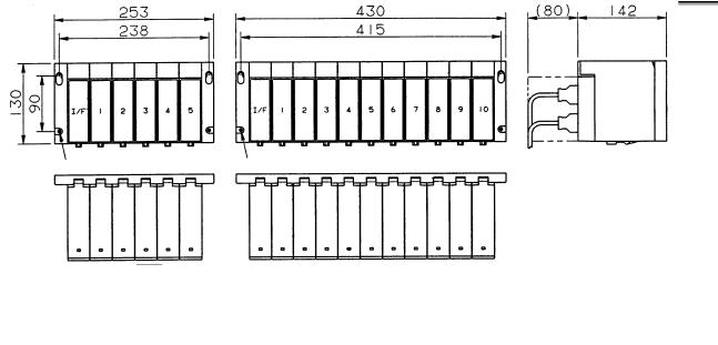
3.3 OUTER DIMENSION OF I/O Unit
Horizontal base units (ABU05A and ABU10A)
Hole for an M4 screw (4 places) |
Hole for an M4 screw (4 places) |
- 11 -

3.INSTALLATION |
CONNECTION |
B-61813E/04 |
Vertical base units (ABU05B and ABU10B)
Hole for an M4 screw (2 places) |
Hole for an M4 screw (4 places) |
|
|
*The ABU05B and ABU10B units that were shipped early on are housed in a metal case.
The distances between mounting holes for the metal case and their size are the same as for the plastic case used for the current units. However, the width of the metal case differs from that of the plastic case as listed below.
|
ABU05B |
|
ABU10B |
|
|
Plastic case |
Metal case |
Plastic case |
Metal case |
Width |
107mm |
110mm |
213mm |
217mm |
- 12 -
B-61813E/04 |
|
|
|
CONNECTION |
|
3.INSTALLATION |
|||
|
|
|
|
Table 3.3 Heat value and weight of each module |
|
|
|||
|
|
Module name |
|
Basic heat value |
Heat value per one I/O point |
Weight (g) |
|||
|
|
|
(W) |
|
(W) |
|
|||
|
|
|
|
|
|
|
|
||
|
|
ABU10A |
|
- |
|
- |
|
600 |
|
|
|
ABU10B |
|
- |
|
- |
|
740 |
|
|
|
ABU05A |
|
- |
|
- |
|
350 |
|
|
|
ABU05B |
|
- |
|
- |
|
380 |
|
|
|
AIF01A |
|
1.2 |
|
- |
|
300 |
|
|
|
AIF01A2 |
|
1.2 |
|
- |
|
300 |
|
|
|
AIF01B |
|
1.2 |
|
- |
|
270 |
|
|
|
AIF02C |
|
1.2 |
|
- |
|
300 |
|
*1 |
|
AID32A1 |
|
1.2 |
|
0.23 |
|
250 |
|
*2 |
|
AID32B1 |
|
1.2 |
|
0.23 |
|
250 |
|
|
|
AID32H1 |
|
1.2 |
|
0.23 |
|
250 |
|
|
|
AID16C |
|
0.1 |
|
0.21 |
|
300 |
|
|
|
AID16K |
|
0.1 |
|
0.21 |
|
300 |
|
|
|
AID16D |
|
0.1 |
|
0.21 |
|
300 |
|
|
|
AID16L |
|
0.1 |
|
0.21 |
|
300 |
|
*3 |
|
AID32E1 |
|
0.1 |
|
0.23 |
|
220 |
|
|
|
AID32E2 |
|
0.1 |
|
0.23 |
|
220 |
|
*4 |
|
AID32F1 |
|
0.1 |
|
0.23 |
|
220 |
|
|
|
AID32F2 |
|
0.1 |
|
0.23 |
|
220 |
|
|
|
AIA16G |
|
0.1 |
|
0.21 |
|
300 |
|
*5 |
|
AOD32A1 |
|
0.3 |
|
- |
|
220 |
|
|
|
AOD08C |
|
0.1 |
|
0.04+0.4×IL2 |
|
380 |
|
|
|
AOD08D |
|
0.1 |
|
0.04+0.6×IL2 |
|
380 |
|
|
|
AOD08DP |
|
0.1 |
|
0.04+0.1×IL2 |
|
310 |
|
|
|
AOD16C |
|
0.1 |
|
0.04+1.4×IL2 |
|
300 |
|
|
|
AOD16D |
|
0.1 |
|
0.04+1.4×IL2 |
|
320 |
|
|
|
AOD16D2 |
|
0.1 |
|
0.04+0.1×IL2 |
|
320 |
|
|
|
AOD16D3 |
|
0.1 |
|
0.04+0.1×IL2 |
|
320 |
|
|
|
AOD16DP |
|
0.1 |
|
0.04+1.8×IL2 |
|
310 |
|
*6 |
|
AOD32C1 |
|
0.1 |
|
0.01+0.8×IL2 |
|
220 |
|
|
|
AOD32C2 |
|
0.1 |
|
0.01+0.8×IL2 |
|
220 |
|
*7 |
|
AOD32D1 |
|
0.1 |
|
0.01+0.8×IL2 |
|
200 |
|
|
|
AOD32D2 |
|
0.1 |
|
0.01+0.8×IL2 |
|
200 |
|
|
|
AOA05E |
|
0.1 |
|
0.13+1.5×IL |
|
370 |
|
|
|
AOA08E |
|
0.1 |
|
0.13+1.5×IL |
|
370 |
|
|
|
AOA12F |
|
0.1 |
|
0.11+1.5×IL |
|
320 |
|
|
|
AOR08G |
|
0.1 |
|
0.3+0.1×IL2 |
|
300 |
|
|
|
AOR16G |
|
0.1 |
|
0.3+0.1×IL2 |
|
350 |
|
|
|
AOR16H2 |
|
0.1 |
|
0.3+0.1×IL2 |
|
250 |
|
|
|
AIO40A |
|
Input |
0.2 |
|
0.23 |
|
350 |
|
|
|
Output |
|
0.01+1.3×IL |
|
|||
|
|
|
|
|
|
|
|
||
|
|
AAD04A |
|
3.1 |
|
- |
|
350 |
|
|
|
AAD04B |
|
3.1 |
|
- |
|
370 |
|
|
|
ADA02A |
|
3.1 |
|
- |
|
350 |
|
|
|
ADA02B |
|
3.1 |
|
- |
|
350 |
|
|
|
ACT01A |
|
4.1 |
|
- |
|
220 |
|
|
|
ATI04A |
|
4.0 |
|
- |
|
260 |
|
|
|
ATI04B |
|
4.0 |
|
- |
|
260 |
|
|
|
ATB01A |
|
- |
|
- |
|
100 |
|
|
|
ATB01B |
|
- |
|
- |
|
120 |
|
- 13 -
3.INSTALLATION |
CONNECTION |
|
B-61813E/04 |
||
|
|
|
|
|
|
|
Module name |
Basic heat value |
Heat value per one I/O point |
Weight (g) |
|
|
(W) |
|
(W) |
||
|
|
|
|
||
|
Optical I/O Link adapter |
- |
|
- |
100 |
|
I/O Link dummy unit |
- |
|
- |
120 |
•Total ‘Heat value per 1 I/O point’ for simultaneous ON points plus ‘Basic heat value’ is the heat value of the module.
•IL : Load current of output
•*1 to *7 : "AxD32x" produced to the old specification is
equivalent to "AxD32x1" (with additional "1" at the end) produced to the current specification. (Example: Old specification AID32E → AID32E1)
- 14 -
B-61813E/04 |
CONNECTION |
3.INSTALLATION |
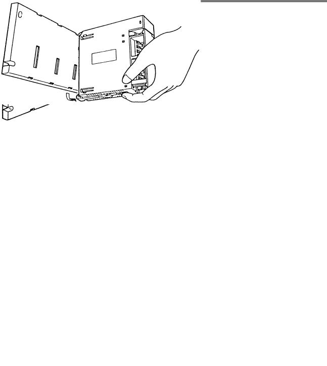
3.4 MOUNTING AND DISMOUNTING MODULES
Interface modules and various types of I/O modules can be mounted to and dismounted from the base unit easily as shown below.
Mounting
Hang the hook at the top of the module on the groove in the upper side of the base unit, and make the connector of the module engage with that of the base unit. Push the module in the lower groove of the base unit till the stopper in the lower side of the module stops.
Dismounting
Release the stopper by pushing the lever at the bottom of the module, and then push the module upwards.
- 15 -

4.CONNECTION |
CONNECTION |
B-61813E/04 |
4 CONNECTION
- 16 -
B-61813E/04 |
CONNECTION |
4.CONNECTION |
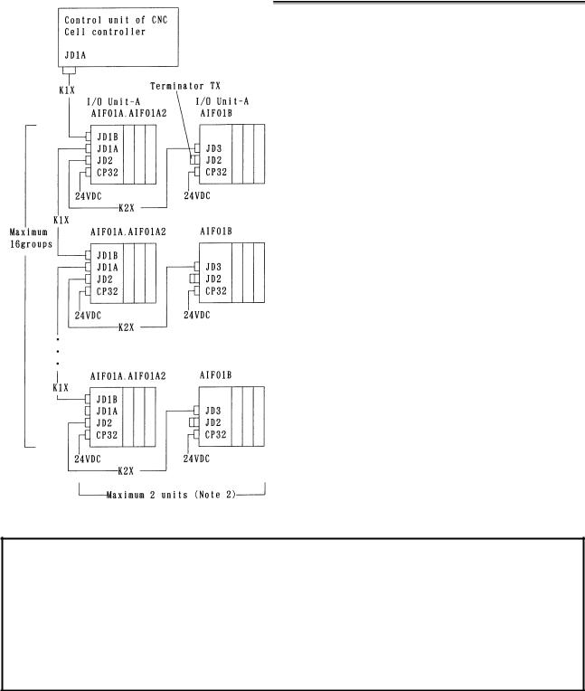
4.1 GENERAL CONNECTION DIAGRAM
NOTE
1Number of I/O Units and connecting method are restricted depending on the allocation of the I/O points. Refer to the section 1.2,"Allocation of I/O points."
2If the master unit is the F-D Mate, one group can consist of up to four I/O Units.
3Cable K1X can be an optical fiber cable by using the optical I/O link adapter.
See chapter 10.
4Terminator TX is required for connector JD2 of the AIF01B that is the last unit to be connected in the group. If no AIF01B is in use, no terminator has to be attached to the
JD2 connector of the AIF01A or AIF01A2.
-17 -

4.CONNECTION |
CONNECTION |
B-61813E/04 |
4.2 CONNECTING INPUT POWER SOURCE
Connect the following power source with the connector CP32 or CP1 of the interface module (AIF01A, AIF01A2, AIF01B, or AIF02C).
•Voltage: 24VDC ±10%
•Current: Determine from Table 4.4
AIF01A / AIF01B / AIF02C CP32
1 |
+24V |
2 |
GND |
3 |
|
AIF01A2
|
CP1 |
|
1 |
|
+24V |
2 |
|
GND |
3 |
|
|
SORIAU JAPAN (manufactured by former Nippon Burndy) Tri-pole connector (Brown)
Housing : SMS3PNS-5 A63L-0001-0202#3LN Contact : RC16M-SCT3 A63L-0001-0226
24VDC
Tyco Electronics
Housing : 1-178288-3
Contact : 1-175218-5
Housing and contact set
A02B-0120-K324
24VDC
NOTE
Turn ON the power for the I/O Unit just when or before the power for the CNC or the cell controller is turned ON. When the CNC or cell controller power is turned OFF, make sure to turn the power to the I/O Unit OFF as well. If the power is not turned on and off according to the above procedure, an error occurs in the CNC or the controller, or the I/O Unit is not normally connected to the power.
Power for the master device
Power for the I/O Unit
t ≥ 500 ms (Turn ON of the power for I/O Unit can be late 500 ms or less.)
- 18 -
 Loading...