


B-64647EN-01
Table of contents
 Loading...
<
+
HMI
SETUP MANUAL
B-64647EN/01
www.hongdiancnc.com
www.hongdiancnc.com
• No part of this manual may be reproduced in any form.
• The design and specifications of this product are subject to change due to
improvements.
The products in this manual are controlled based on Japan's "Foreign Exchange and
Foreign Trade Law".
Furthermore, the product may also be controlled by re-export regulations of the United
States government.
Should you wish to export or re-export these products, please contact FANUC for advice.
This manual attempts to include information as much as possible.
There are, however, a very large number of operations that must not or cannot be
performed, and if the manual contained them all, it would be enormous in volume.
It is, therefore, requested to assume that any functions not described in this manual are
"not equipped in this product."
Program and device names belonging to companies other than FANUC in this manual
include registered trademarks of their respective companies.
However, the ® and ™ marks may be omitted for some of those names.
www.hongdiancnc.com
www.hongdiancnc.com
SAFETY PRECAUTIONS
DEFINITION OF WARNING, CAUTION, NOTE, AND MEMO
s-1
1
2
3
4
5
6
7
8
A1
A2
Z
B-64647EN/01
When using FANUC iHMI, you must comply with the instructions written in "SAFETY
PRECAUTIONS".
This manual includes safety precautions for protecting the user and preventing
damage t
o
the machine. Precautions are classified into " Warning" and "
Caution" according to the degree of the risk or severity of damage.
Also, supplementary information is described as "Note" and "Memo".
Read these indications thoroughly before using this product.
*
Read this manual carefully, and store it in a safe place.
SAFETY PRECAUTIONS
DEFINITION OF WARNING, CAUTION,
NOTE, AND MEMO
WARNING
Used if a danger resulting in the death or serious injury of the user is
expected to occur if he or she fails to observe the approved procedure.
CAUTION
Used if a danger resulting in the minor injury of the user or equipment
damage is expected to occur if he or she fails to observe the approved
procedure.
NOTE
Used if points to keep in mind not related to WARNING or CAUTION are to
be indicated.
MEMO
Used if supplementary explanations for operation or additional information
not related to WARNING or CAUTION are to be indicated.
!
!
!
!
www.hongdiancnc.com
www.hongdiancnc.com

SAFETY PRECAUTIONS
GENERAL PRECAUTIONS
s-2
1
2
3
4
5
6
7
8
A1
A2
Z
B-64647EN/01
The following warnings and cautions provide information to be noted when
handing the CNC device for safer use of the machine with the CNC device.
GENERAL PRECAUTIONS
WARNING
• Carefully check that data you want to enter is correctly entered before
performing the next operation. Operation with incorrect data may cause
unexpected behavior of the machine, resulting in damage to the work or
machine or injury.
• Carefully check that program command value, offset value, curren
t
po
si
tion, and external signal settings, etc. are correct before starting the
machine for operation, such as machining the work. Also, perform tria
l
op
eration, such as using the single block, feed speed override, or machi
ne
l
ock function, or operating without a tool or work, to carefully check that th
e
machine operates correctly.
• Check that an appropriate feed speed value is specified for the operation.
T
h
e maximum feed speed is normally limited for each machine. Follow the
manual of the machine as well because the optimal speed is differen
t
de
pending on the operation.
Operation with an incorrect speed may cause unexpected load to t
he
ma
ch
ine, resulting in damage to the work or machine or injury.
• Before using the tool offset function, carefully check the offset direction a
nd
v
al
ue. Operation with incorrect data may cause unexpected behavior of
the
ma
chine, resulting in damage to the work or machine or injury.
• Optimal values are set to the CNC and PMC parameters, so they do no
t
no
r
mally need to be changed. If you change the parameter for so
me
r
eason, fully understand its function before change. An incorrect parameter
setting may cause unexpected behavior of the machine depending on th
e
s
etting value, resulting in damage to the work or machine or injury.
CAUTION
• After pressing the power on button, do not touch any key on the keyboard
un
til the screen appears. Some keys are used for maintenance or specia
l
op
eration and may cause unexpected behavior.
• NC programs, parameters, and variables are stored in the non-volatile
me
mory
in the CNC device. These data are usually not lost by powering
on/off. However, precious data stored in the non-volatile memory may
be
l
ost due to incorrect operation or may have to be erased due to faul
t
re
covery.
To recover fast from such an unexpected situation, back up all kinds of
da
t
a beforehand.
• There are some embedded machine operations and screen function
s
i
ns
talled by machine tool builders (MTB). For how to use them and
precautions, refer to the appropriate manual provided by each
manufacturer.
!
!
www.hongdiancnc.com
www.hongdiancnc.com

SAFETY PRECAUTIONS
GENERAL WARNINGS FOR CNC APPLICATION DEVELOPMENT
s-3
1
2
3
4
5
6
7
8
A1
A2
Z
B-64647EN/01
0.1
GENERAL WARNINGS FOR CNC
APPLICATION DEVELOPMENT
WARNING
Be careful enough for the following warnings when you develop two or more
applications or use networks.
If you neglect them, there is a danger of the user being injured or there is a
da
nge
r of both the user being injured and the equipment being damaged.
1.Be careful enough if you write an identical NC data, an identical PMC data
or
a s
eries of related data set by two or more above applications including
network functions. Because they are executed based on each individual
cycles (in other words, asynchronous cycles), there is a possibility that the
data will be written in an unexpected order.
Therefore, do NOT write above data in the following cases.
- Applications and network functions
- Two or more applications
- Two or more network functions
Data, applications and network functions of interest are listed in below.
Howe
ve
r, all may not be listed completely because new features will be
added in the future.
2.Be careful enough that you must prevent PMC signals in the same by
te
from
being written by the following two or more applications including
network functions. While an application reads and writes one byte of PMC
signals, other applications may write the same byte.
3.Be careful enough if you process a PMC signal set that is related to a
NC
func
tion by using the following two or more applications including network
functions. Because they are executed based on each individual cycles (in
other words, asynchronous cycles), there is a possibility that the NC may
receive the PMC signal set in an unexpected order.
4.Generally, when multi-byte data are read or written at once among t
he
following two or more applications including network functions, the
coherency of the read multi-byte data (in other words, reading all latest
data at once) is not guaranteed. To ensure the coherency of the multi-byte
data, prepare flags to notify the completion of reading or writing process
that is separated from the entity of the data and make the handshaking
process to access the data by using the flags.
!
www.hongdiancnc.com
www.hongdiancnc.com
SAFETY PRECAUTIONS
GENERAL WARNINGS FOR CNC APPLICATION DEVELOPMENT
s-4
1
2
3
4
5
6
7
8
A1
A2
Z
B-64647EN/01
CAUTION
Data List Table
List Table of Applications and Network Functions
5.CNC has functions that read or write PMC signals in other than the G/F
address. Be careful enough if the above mentioned applications and
network read or write PMC signals used by these functions. When reading
or writing the same PMC signal, applications or CNC functions may work in
an unexpected manner.
As for the CNC functions of interest, refer to the connection manual
(
Function) (B-64483EN-1) ”Appendix B. List of Functions Using PMC
Signals Other Than G/F Address”.
!
Category Data
General data for NC Parameter, Tool compensation value and related
data,
Work zero offset value and related data,
Workpiece coordinate system shift value and related
data,
Macro variable, P-CODE variable, Program and
related data,
Tool management function data, Tool life
management data,
Error compensation related data ,
Overtravel check (Interference check) related data ,
Software operator’s panel related data
PMC data PMC signal, PMC parameter
Data for Laser,
Punch press or Wire
cut
Tool data for punch press and related data, Safety
zone data and related data, Laser cutting condition
data and related data, Laser oscillator setting data
and related data, Wire consumption compensation
data, Guide position compensation data, Workpiece
leveling data
Other data Parameters for Data Server, Parameters for network
setting
Category Functions
Applications PMC Ladder, Macro Executor, C Language
Executor, FANUC PICTURE, FOCAS2
Network functions FL-net, EtherNet/IP, PROFINET, Modbus/TCP,
PROFIBUS-DP, DeviceNet, CC-Link
www.hongdiancnc.com
www.hongdiancnc.com
PREFACE
RELATED MANUALS
p-1
1
2
3
4
5
6
7
8
A1
A2
Z
B-64647EN/01
The iHMI consists of applications that support CNC operations and the "Home
screen" that starts each application. The iHMI allows you to customize each
application and add your custom applications to the Home screen. This manual
describes the customization method and specifications of the iHMI.
For details about the iHMI and iHMI applications, see "FANUC iHMI Home Screen
OPERATOR'S MANUAL" (B-64644EN) and "FANUC iHMI CNC Operation Screen
OPERATOR'S MANUAL" (B-64644EN-1).
0.1
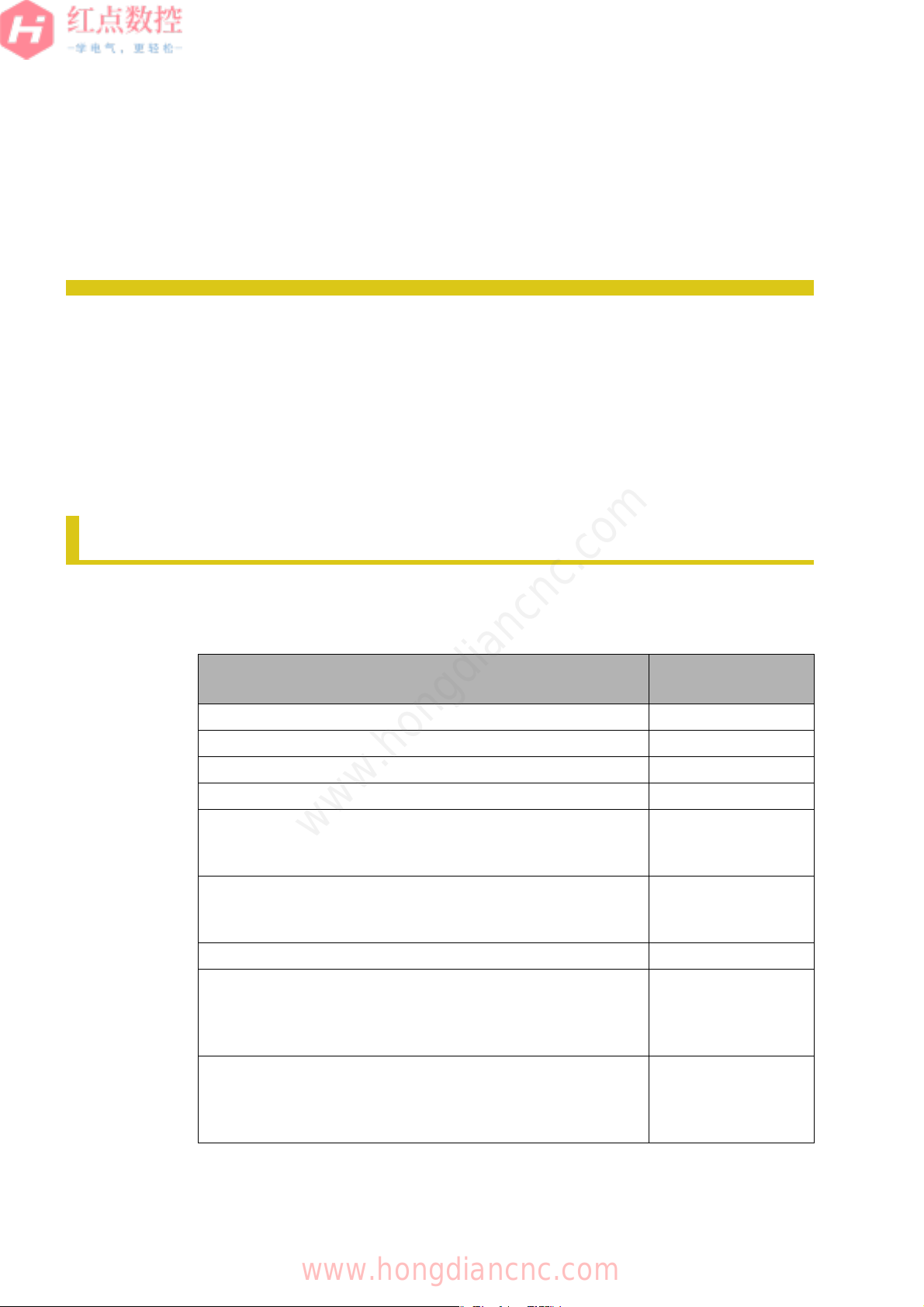
The table below lists related manuals.
Table1 Related Manuals List
PREFACE
1 RELATED MANUALS
Manual name Specification
number
FANUC iHMI Home Screen OPERATOR'S MANUAL B-64644EN
FANUC iHMI CNC Operation Screen OPERATOR'S MANUAL B-64644EN-1
FANUC iHMI Machining Cycle OPERATOR'S MANUAL B-64644EN-2
FANUC iHMI Set-up Guidance OPERATOR'S MANUAL B-64644JA-3
FANUC Series 30i-MODEL B
FANUC Series 31i-MODEL B
FANUC Series 32i-MODEL B PARAMETER MANUAL
B-64490EN
FANUC Series 30i-MODEL B
FANUC Series 31i-MODEL B
FANUC Series 32i-MODEL B MAINTENANCE MANUAL
B-64485EN
FANUC PICTURE OPERATOR'S MANUAL B-66284EN
FANUC Series 30i-MODEL B
FANUC Series 31i-MODEL B
FANUC Series 32i-MODEL B CONNECTION MANUAL
(HARDWARE)
B-64483EN
FANUC Series 30i-MODEL B
FANUC Series 31i-MODEL B
FANUC Series 32i-MODEL B CONNECTION MANUAL
(FUNCTION)
B-64483EN-1
www.hongdiancnc.com
www.hongdiancnc.com

PREFACE
RELATED MANUALS
p-2
1
2
3
4
5
6
7
8
A1
A2
Z
B-64647EN/01
FANUC Series 30i-MODEL B
FANUC Series 31i-M
O
DEL B
FANUC Series 32i-
M
ODEL B Common to Lathe System/
Machining Center System OPERATOR'S MANUAL
B-64484EN
FANUC Series 30i-MODEL B
FANUC Series 31i-M
O
DEL B
FANUC Series 32i-MO
D
EL B
FANUC Series 35i-MO
D
EL B PMC PROGRAMMING MANUAL
B-64513EN
FANUC MANUAL GUIDE i Common to Lathe System/Machining
Center System OPERATOR'S MANUAL
B-63874EN
FANUC MANUAL GUIDE i SET-UP GUIDANCE FUNCTIONS
OPERATOR'S MANUAL
B-63874EN-1
FANUC Interactive Programming Function for Complex Lathe
OPERATOR'S MANUAL
B-64654EN
CNC Screen Display Function OPERATOR'S MANUAL
B-63164EN
Manual name Specification
number
www.hongdiancnc.com
www.hongdiancnc.com

c-1
1
2
3
4
5
A
B-64647EN/01
CHAPTER CONTENTS
1 OVERVIEW . . . . . . . . . . . . . . . . . . . . . . . . . . . . . . . . . . . . . . . . . . . . . .1
2 SETTING UP iHMI APPLICATIONS . . . . . . . . . . . . . . . . . . . . . . . . . .13
3 CREATING A USER APPLICATION . . . . . . . . . . . . . . . . . . . . . . . .185
4 MAINTENENCE . . . . . . . . . . . . . . . . . . . . . . . . . . . . . . . . . . . . . . . . .205
5 PARAMETERS . . . . . . . . . . . . . . . . . . . . . . . . . . . . . . . . . . . . . . . . .231
A APPENDIX . . . . . . . . . . . . . . . . . . . . . . . . . . . . . . . . . . . . . . . . . . . . .313
www.hongdiancnc.com
www.hongdiancnc.com

c-2
1
2
3
4
5
6
7
8
A1
A2
Z
B-64647EN/01
www.hongdiancnc.com
www.hongdiancnc.com

c-3
1
2
3
4
5
6
7
8
A1
A2
Z
B-64647EN/01
SAFETY PRECAUTIONS . . . . . . . . . . . . . . . . . . . . . . . . . . . . . . . s-1
DEFINITION OF WARNING, CAUTION, NOTE, AND MEMO ...........s-1
GENERAL PRECAUTIONS ................................................................s-2
GENERAL WARNINGS FOR CNC APPLICATION
DEVELOPMENT..................................................................................s-3
PREFACE ............................................................................................... p-1
1 RELATED MANUALS .......................................................................... p-1
1 OVERVIEW . . . . . . . . . . . . . . . . . . . . . . . . . . . . . . . . . . . . . . . . . .1
1.1 iHMI SETUP OVERVIEW ..............................................................2
1.1.1 Setup Overview ................................................................................ 2
1.1.1.1 Customizing applications registered with the iHMI ................... 2
1.1.1.2 Overall iHMI settings ................................................................. 6
1.1.2 Environment Required for iHMI Customization ................................ 8
1.1.2.1 User application ........................................................................ 8
1.1.2.2 FANUC PICTURE ..................................................................... 9
1.1.2.3 Machine alarm diagnosis guidance table ................................ 10
1.1.3 iHMI Hardware Performance Table ................................................ 10
1.2 iHMI MAINTENANCE OVERVIEW .............................................12
2 SETTING UP iHMI APPLICATIONS . . . . . . . . . . . . . . . . . . . . . .13
2.1 iHMI APPLICATION SETUP OVERVIEW ...................................14
2.1.1 iHMI Folder Configuration .............................................................. 14
2.1.1.1 Folder configuration inside the CNC ....................................... 14
2.1.2 Customizable Applications ............................................................. 15
2.2 CONFIGURATION FILES THAT AFFECT THE ENTIRE iHMI ...17
2.2.1 Application Definition File ............................................................... 17
2.2.1.1 Starting an application with a screen specified ....................... 19
2.2.1.2 Starting iHMI applications from shortcuts ............................... 19
2.2.2 iHMI Whole Configuration File ....................................................... 22
2.2.3 Individual Settings Common to the Applications ............................ 24
2.2.3.1 Hiding the vertical soft keys .................................................... 24
2.2.3.2 Setting an animation to be used when a slide is displayed ..... 25
2.3 SETTING UP BASIC FUNCTIONS .............................................27
2.3.1 Customizing the Home Screen ....................................................... 27
2.3.1.1 Changing the background of the home screen ....................... 27
2.3.1.2 Adding a shutdown button ...................................................... 27
TABLE OF CONTENTS
www.hongdiancnc.com
www.hongdiancnc.com

c-4
1
2
3
4
5
6
7
8
A1
A2
Z
B-64647EN/01
2.3.2 Customizing the Status Display ..................................................... 29
2.3.2.1 Adding status icons and character string display ................... 29
2.3.3 Setting the Machine Alarm Diagnosis ............................................ 36
2.3.3.1 Alarm and operator message types that can be added .......... 36
2.3.3.2 Diagnosable numbers ............................................................. 36
2.3.3.3 Environments required to create failure diagnosis messages 37
2.3.3.4 Machine alarm diagnosis guidance table ............................... 37
2.3.3.5 Creating failure diagnosis messages ...................................... 42
2.3.3.6 Creating different language messages ................................... 50
2.4 SETTING UP THE PLANNING APPLICATION .......................... 54
2.4.1 Setting Up Tool Management Function ......................................... 54
2.4.1.1 NC tool database management .............................................. 54
2.4.1.2 Tool management function customization .............................. 56
2.4.2 Setting Up Cycle Time Estimation Function ................................... 57
2.4.2.1 Application definition file ......................................................... 57
2.4.2.2 Auxiliary function time setting window .................................... 57
2.4.2.3 Adding an auxiliary function time ............................................ 58
2.4.2.4 Changing an auxiliary function time ........................................ 60
2.4.2.5 Deleting an auxiliary function time .......................................... 60
2.5 SETTING UP THE MACHINING APPLICATION ........................ 62
2.5.1 Setting Up the CNC Operation Screen .......................................... 62
2.5.1.1 Configuration file to use the multi-path edit function ............... 62
2.5.1.2 Setting the coordinate axes display and soft key display ....... 64
2.5.1.3 Setting the number of divided areas of the multi-path display 65
2.5.1.4 Hiding the modal G codes ...................................................... 68
2.5.1.5 Settings related to each mode base screen ........................... 68
2.5.1.6 Setting the spindle rotation direction icon display ................... 70
2.5.1.7 Setting the uniform peripheral speed control mode icon
display .................................................................................... 73
2.5.1.8 Setting the traveling direction guide in the JOG, HND, INC,
and REF mode base screens ................................................. 74
2.5.1.9 Setting the workpiece coordinates slide ................................. 76
2.5.1.10 Setting the program manager slide ........................................ 77
2.5.1.11 Opening/closing the custom macro variable slide .................. 78
2.5.1.12 Displaying custom macro variable numbers and values ........ 79
2.5.1.13 Editing custom macro variables .............................................. 82
2.5.1.14 Displaying custom macro variable names .............................. 86
2.5.1.15 Conditions to use the machining simulation function .............. 87
2.5.1.16 Configuration file to use the machining simulation function .... 88
2.5.1.17 Machining simulation screen .................................................. 90
2.5.1.18 Configuration file to use the machining cycle creation
function ................................................................................... 98
2.5.1.19 Display settings of the MEM mode base screen .................... 99
2.5.1.20 Setting program guidance messages ................................... 101
2.5.1.21 Setting up M code input function .......................................... 105
2.5.1.22 Setting up the fixed sentence function .................................. 109
www.hongdiancnc.com
www.hongdiancnc.com

c-5
1
2
3
4
5
6
7
8
A1
A2
Z
B-64647EN/01
2.5.2 Setting Up the iHMI Machining Cycle ........................................... 113
2.5.3 Setting Up the iHMI Set-up Guidance .......................................... 113
2.5.3.1 Manually setting in the P-CODE variable .............................. 114
2.5.3.2 Setting on the MANUAL GUIDE i screen .............................. 121
2.5.4 Setting Up the Machine Collision Avoidance Function ................. 125
2.5.4.1 Creating a 3D machine model .............................................. 125
2.5.4.2 Setting various settings of the machine collision avoidance
function ................................................................................. 127
2.5.4.3 Setting the common items .................................................... 129
2.5.4.4 Setting the machine configuration ......................................... 131
2.5.4.5 Configuring the individual path settings ................................ 149
2.5.4.6 Preview time of the machine collision avoidance function .... 153
2.5.4.7 Signals available during the execution of the machine
collision avoidance function .................................................. 156
2.6 SETTING UP THE IMPROVEMENT APPLICATION ................159
2.6.1 Importing/Exporting Logs Collected with the Data Logger
Function ........................................................................................ 159
2.6.1.1 Log item configuration file ..................................................... 159
2.6.1.2 Log file .................................................................................. 164
2.6.2 Setting Up the Maintenance Manager .......................................... 166
2.6.2.1 Setting parts placement information ..................................... 167
2.6.2.2 Standard icons list ................................................................. 168
2.6.2.3 Switching maintenance items display ................................... 169
2.6.2.4 Outputting the display switch settings of the maintenance
items ..................................................................................... 170
2.6.2.5 Maintenance items display switch configuration file ............. 170
2.7 SETTING UP THE UTILITY APPLICATION ..............................173
2.7.1 Setting Up the Manual Viewer Function ....................................... 173
2.7.1.1 Manual information configuration file .................................... 173
2.7.1.2 Manual viewer tag list ........................................................... 174
2.7.1.3 Import folder configuration .................................................... 177
2.7.1.4 Naming rules for manual file update ..................................... 178
2.7.2 Setting Up the Web Browser Function ......................................... 179
2.7.2.1 Description of the Web browser configuration file ................. 179
2.7.2.2 Setting the start page ............................................................ 180
2.8 CREATING PROGRAM STORAGE FILES ...............................181
2.8.1 Program Storage Files ................................................................. 181
2.8.2 Creating a Program Storage File (Ncprog.bin) ............................. 181
2.8.3 Program Storage File Edit Library (Ncprog.dll) ............................ 181
3 CREATING A USER APPLICATION . . . . . . . . . . . . . . . . . . . .185
3.1 OVERVIEW OF CREATING A USER APPLICATION ..............186
3.1.1 Adding an Application to the iHMI ................................................ 186
3.1.2 User Application ........................................................................... 187
3.2 HOW TO CREATE A USER APPLICATION .............................188
3.2.1 Overview of Creating an Application ............................................ 188
www.hongdiancnc.com
www.hongdiancnc.com

c-6
1
2
3
4
5
6
7
8
A1
A2
Z
B-64647EN/01
3.2.2 Using the iHMI Library ................................................................. 188
3.2.2.1 Application Manager ............................................................. 189
3.2.2.2 Overlapping the user application with the iHMI application .. 190
3.2.2.3 Starting a specific application from the user application ....... 192
3.2.2.4 Displaying a specific screen when starting the user
application ............................................................................ 194
3.3 CUSTOMIZING A SCREEN WITH FANUC PICTURE ............. 196
3.3.1 Creating a New Operator's Panel Screen .................................... 196
3.3.2 Changing an Operator's Panel Screen ........................................ 199
3.3.3 Simultaneous Display with Another Application ........................... 201
4 MAINTENENCE . . . . . . . . . . . . . . . . . . . . . . . . . . . . . . . . . . . . .205
4.1 DATA BACKUP/RESTORE ...................................................... 206
4.1.1 Starting the Backup Screen ......................................................... 207
4.1.2 Saving Data in a Batch ................................................................ 212
4.1.3 Restoring Data in a Batch ............................................................ 213
4.1.4 Saving Data Individually ............................................................... 214
4.1.5 Restoring Data Individually .......................................................... 214
4.1.6 Displaying the Details of Batch Save and Restore Results ......... 214
4.2 AUTOMATIC DATA BACKUP .................................................. 216
4.2.1 Backing Up to External Memory .................................................. 217
4.2.1.1 List of output text data .......................................................... 218
4.3 HOW TO UPDATE THE SOFTWARE ...................................... 220
4.3.1 Preparation .................................................................................. 220
4.3.1.1 Checking the iHMI version ................................................... 220
4.3.1.2 Checking whether the EWF is enabled/disabled
(for PANEL iH Pro only) ....................................................... 221
4.3.2 Updating the iHMI Basic Software for the PANEL iH .................. 222
4.3.2.1 Folder configuration .............................................................. 222
4.3.2.2 Backing up iHMI data ........................................................... 222
4.3.2.3 Installing the iHMI ................................................................. 223
4.3.2.4 Restoring backed-up iHMI data ............................................ 225
4.3.3 Updating the iHMI Basic Software for the PANEL iH Pro ............ 226
4.3.3.1 Backing up iHMI data ........................................................... 226
4.3.3.2 Disabling the EWF ................................................................ 227
4.3.3.3 Uninstalling the iHMI ............................................................ 228
4.3.3.4 Installing the iHMI ................................................................. 228
4.3.3.5 Restoring backed-up iHMI data ............................................ 228
4.3.3.6 Enabling the EWF ................................................................. 229
www.hongdiancnc.com
www.hongdiancnc.com

c-7
1
2
3
4
5
6
7
8
A1
A2
Z
B-64647EN/01
5 PARAMETERS . . . . . . . . . . . . . . . . . . . . . . . . . . . . . . . . . . . . .231
5.1 PARAMETERS TO DISABLE EDITING OF PROGRAMS ........233
5.2 PARAMETER OF SUBPROGRAM CALLS ...............................238
5.3 PARAMETER OF PROGRAM PROTECTION KEYS ...............239
5.4 PARAMETERS TO DISABLE EDITING IN THE AUTOMATIC
OPERATION STOP STATE ......................................................240
5.5 PARAMETER TO CHANGE THE NUMBER OF DIGITS FOR
PROGRAM NUMBERS .............................................................242
5.6 PARAMETER TO SELECT A DEVICE .....................................243
5.7 PARAMETERS OF THE TROUBLE DIAGNOSIS FUNCTION .244
5.8 PARAMETERS OF THE MACHINING SIMULATION
FUNCTION ................................................................................247
5.9 PARAMETERS OF THE CURRENT POSITION/REMAINING
TRAVEL DISTANCE DISPLAY TILES ......................................251
5.9.1 Parameters to Display Axis Names .............................................. 251
5.9.2 Parameters to Display Extended Axis Names and Subscripts ..... 253
5.9.3 Parameters to Display Coordinate Values ................................... 255
5.9.4 Parameters of Increment System 0.1 nm Display ........................ 257
5.9.5 Parameters of Programmable Diameter/Radius Switching .......... 259
5.9.6 Parameters to Show/Hide Control Axes ....................................... 261
5.9.7 Parameters to Align Control Axes to the Top ............................... 261
5.9.8 Parameters to Change the Order of Displaying Control Axes ...... 262
5.9.9 Parameters to Preset a Workpiece Coordinate System
(Absolute/Overall) ......................................................................... 262
5.10 PARAMETERS OF SERVO LOAD METER DISPLAY ..............264
5.10.1 Parameters to Display Axis Names .............................................. 264
5.10.2 Parameters to Display Extended Axis Names and Subscripts ..... 264
5.10.3 Parameters of Axis Name Switching ............................................ 264
5.10.4 Parameters to Show/Hide Control Axes ....................................... 264
5.10.5 Parameters to Align Control Axes to the Top ............................... 264
5.10.6 Parameters to Change the Order of Displaying Control Axes ...... 265
5.11 PARAMETERS OF MODAL INFORMATION DISPLAY ............266
5.11.1 Parameters of Modal G Codes ..................................................... 266
5.11.2 Parameters of Modal HD.T and NX.T Codes ............................... 268
5.11.3 Parameters of Modal SRPM, SSPM, and SMAX ......................... 271
5.11.4 Parameters of Modal F Codes ..................................................... 271
5.11.5 Parameters of Modal T, D, and H Codes ..................................... 272
5.11.6 Parameters of Modal T Codes ..................................................... 273
5.11.7 Parameters of Modal S Codes ..................................................... 274
5.11.8 Parameters of Modal M Codes (First to Fifth M Codes) ............... 275
5.11.9 Parameters of Modal B Codes (Second Auxiliary Function) ........ 276
5.11.10Parameters of Modal C Codes (Third Auxiliary Function) ........... 279
5.11.11Parameters of Modal A Codes (Fourth Auxiliary Function) ......... 279
5.11.12Parameters of General Modal Information .................................. 280
www.hongdiancnc.com
www.hongdiancnc.com

c-8
1
2
3
4
5
6
7
8
A1
A2
Z
B-64647EN/01
5.12 PARAMETERS OF MACHINING INFORMATION DISPLAY ... 282
5.13 PARAMETER TO DISPLAY FEEDRATE INFORMATION ....... 287
5.13.1 Parameter to Display Feedrate Information ................................. 287
5.13.2 Parameters of the Actual Feedrate Unit ....................................... 287
5.13.3 Parameter to Display the Actual Feedrate ................................... 289
5.13.4 Parameters of the Actual Feedrate Speed Meter ........................ 289
5.14 PARAMETERS OF SPINDLE INFORMATION DISPLAY ........ 291
5.14.1 Parameters of Extended Spindle Names and Subscripts ............ 291
5.14.2 Parameters of the Actual Spindle Speed ..................................... 295
5.14.3 Parameters of the Spindle Speed Meter ...................................... 296
5.14.4 Parameters of the Spindle Load Meter ........................................ 296
5.14.5 Parameters of the Current Load Ratio ......................................... 297
5.15 PARAMETERS OF MACHINING PROGRAM DISPLAY .......... 298
5.15.1 Parameters of Subprogram Calls ................................................. 298
5.15.2 Parameter of Program Content Display ....................................... 300
5.15.3 Parameters of Program Numbers ................................................ 301
5.15.4 Parameters of Display during Program Backward by Manual
Handle Retrace ............................................................................ 302
5.16 PARAMETER OF N NUMBER SEARCH IN A MACHINING
PROGRAM ............................................................................... 304
5.16.1 Parameter of Sequence Numbers ............................................... 304
5.17 PARAMETERS OF SEQUENCE NUMBER STOP ................... 305
5.18 PARAMETERS OF THE CUSTOM MACRO VARIABLE LIST
SLIDE ........................................................................................ 306
5.19 PARAMETERS OF THE MACHINE COLLISION AVOIDANCE
FUNCTION ............................................................................... 308
A APPENDIX . . . . . . . . . . . . . . . . . . . . . . . . . . . . . . . . . . . . . . . . .313
A.1 APPLICATION IDENTIFIER ID ................................................. 314
A.2 CNC OPERATION SCREEN SWITCHING ID
(SUBJECT VALUE) .................................................................. 315
A.3 MAINTENANCE DISPLAY SWITCHING ID
(SUBJECT VALUE) .................................................................. 316
A.4 MDI KEY CODE MAP FOR iHMI .............................................. 324
A.5 FANUC SCREEN COLOR DEFINITION LIST .......................... 333
A.6 FUNCTION SPECIFICATIONS ................................................ 338
A.6.1 CncAppClient Function Specifications ......................................... 338
A.6.2 CncAppClient Notification Message ............................................. 342
A.7 RESOURCES REQUIRED FOR EACH FUNCTION ................ 344
A.7.1 For PANEL iH .............................................................................. 344
A.7.1.1 Memory usage in the iHMI basic functions ........................... 344
A.7.1.2 Amount of memory that can be used in the MTB application 345
A.7.2 For PANEL iH Pro ........................................................................ 345
A.7.2.1 Memory usage in the iHMI basic functions ........................... 346
A.7.2.2 Memory usage in option functions ........................................ 347
A.7.2.3 Amount of memory that can be used in the MTB application 347
www.hongdiancnc.com
www.hongdiancnc.com

1
2
3
4
5
A
1
OVERVIEW
This chapter describes the overview of an environment required to set up the
iHMI and customization.
1.1 iHMI SETUP OVERVIEW ........................................................................ 2
1.2 iHMI MAINTENANCE OVERVIEW......................................................... 12
www.hongdiancnc.com
www.hongdiancnc.com
CHAPTER 1 OVERVIEW
1.1 iHMI SETUP OVERVIEW
2
1
2
3
4
5
6
7
8
A1
A2
Z
B-64647EN/01
1.1
The iHMI allows you to customize iHMI applications and add your custom
applications to the Home screen. There are two types of hardware, FANUC
PANEL iH and FANUC PANEL iH Pro, both of which allow application
customization.
1.1.1 Setup Overview
1.1.1
The iHMI provides the following customization methods according to the machine
equipped with the iHMI or the way of using the operator.
1.1.1.1 Customizing applications registered with the iHMI
1.1.1.1
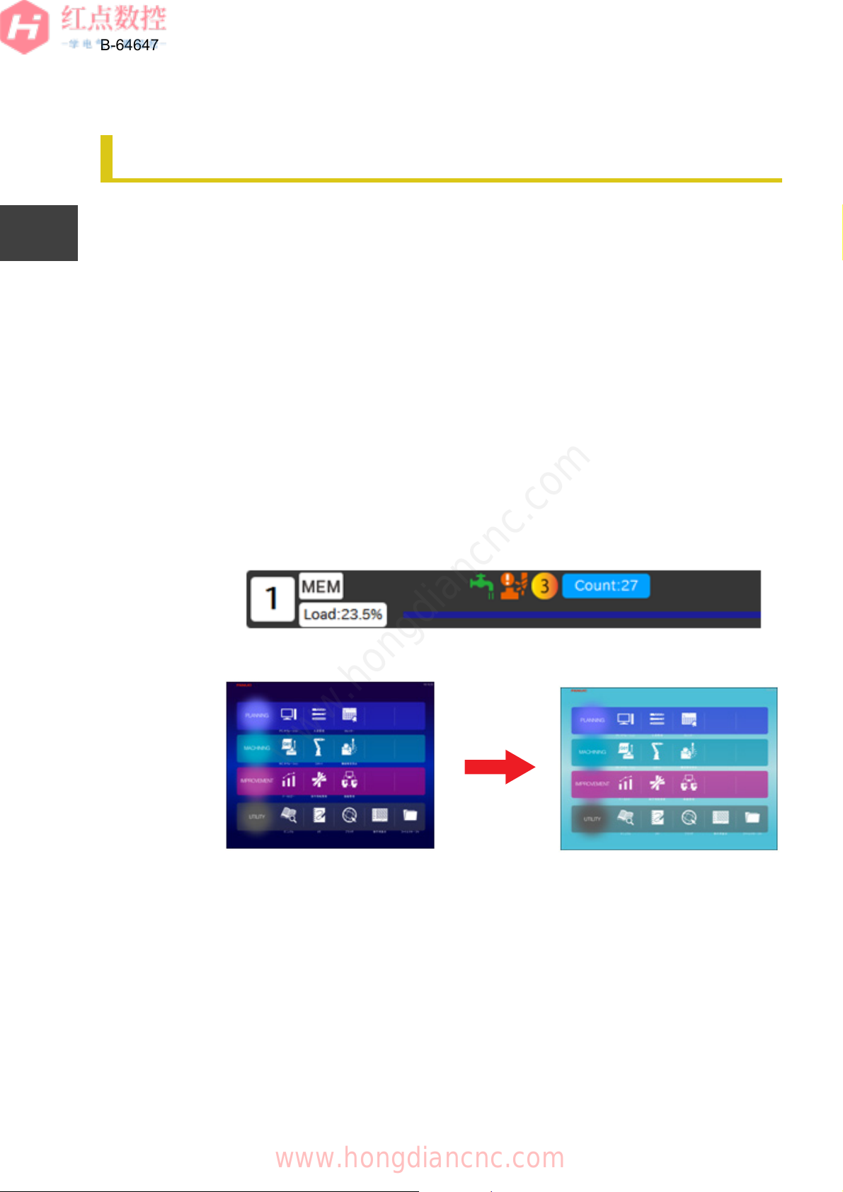
Customize each iHMI application. The following shows customization examples:
Status icon/Home screen
You can add an icon to the status at the top of an iHMI application or change the
background color of the Home screen.
Fig. 1.1.1.1 (a) Adding a Status Icon
Fig. 1.1.1.1 (b) Changing the Background of the Home Screen
1.1 iHMI SETUP OVERVIEW
www.hongdiancnc.com
www.hongdiancnc.com
CHAPTER 1 OVERVIEW
1.1 iHMI SETUP OVERVIEW
3
1
2
3
4
5
6
7
8
A1
A2
Z
B-64647EN/01
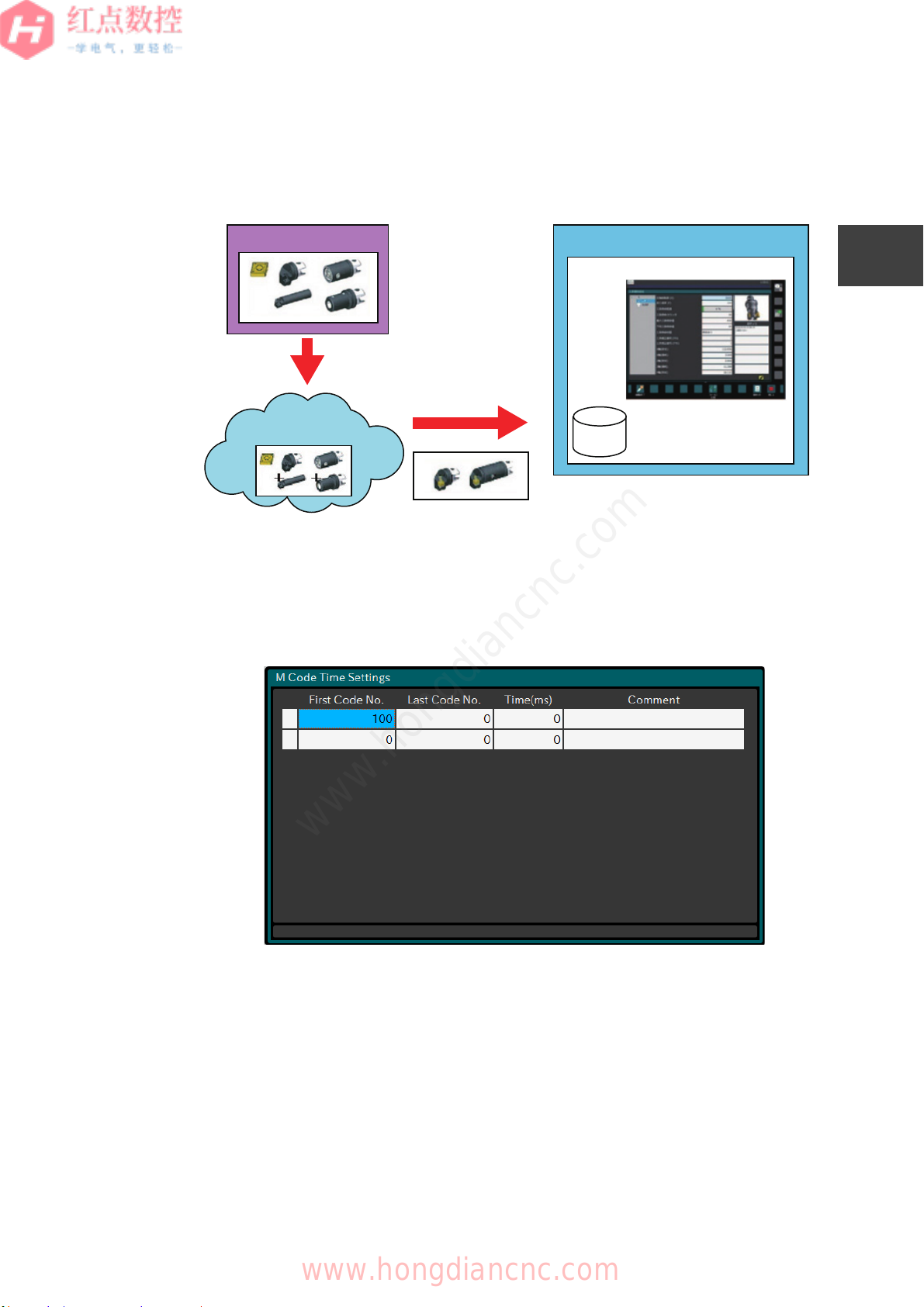
Tool Manager
The Tool Manager allows you to set the options and parameters required for using
the functions and import catalog data.
Fig. 1.1.1.1 (c) Flow of Importing Tool Data
Cycle Time Estimation
The Cycle Time Estimation allows you to set the auxiliary function time.
Fig. 1.1.1.1 (d) Auxiliary function time settings
Tool Data
+iHMI
Tool Manager
Database
Data loading
Select and group tools
Data storing
Tool library
software
www.hongdiancnc.com
www.hongdiancnc.com

CHAPTER 1 OVERVIEW
1.1 iHMI SETUP OVERVIEW
4
1
2
3
4
5
6
7
8
A1
A2
Z
B-64647EN/01
CNC Operation Screen
The CNC operation screen allows you to configure the settings required for using
the functions. You can also register images to a program.
Fig. 1.1.1.1 (e) CNC Operation Screen
Machine Collision Avoidance
The machine collision avoidance allows you to register machine 3D model data
and set the parameters.
Fig. 1.1.1.1 (f) Registering 3D Model Data
Define a
machine model.
Tool definition
VERICUT
www.hongdiancnc.com
www.hongdiancnc.com
CHAPTER 1 OVERVIEW
1.1 iHMI SETUP OVERVIEW
5
1
2
3
4
5
6
7
8
A1
A2
Z
B-64647EN/01
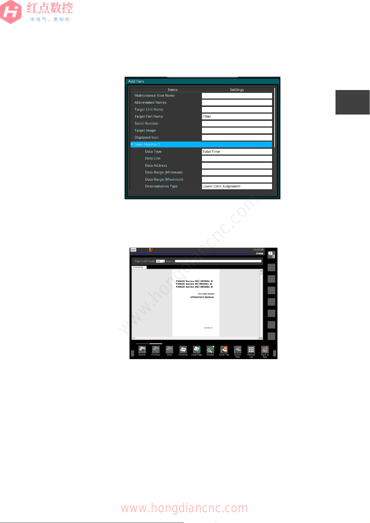
Maintenance Manager
The Maintenance Manager allows you to set the maintenance items.
Fig. 1.1.1.1 (g) Setting the Maintenance Items
Manual Viewer
The manual viewer allows you to add a manual and specify whether to protect it.
Fig. 1.1.1.1 (h) Manual Viewer
For details on how to customize each application, see " Chapter 2 SETTING UP
iHMI APPLICATIONS ".
www.hongdiancnc.com
www.hongdiancnc.com
CHAPTER 1 OVERVIEW
1.1 iHMI SETUP OVERVIEW
6
1
2
3
4
5
6
7
8
A1
A2
Z
B-64647EN/01
1.1.1.2 Overall iHMI settings
1.1.1.2 -
You can configure the overall iHMI settings. The following shows customization
examples:
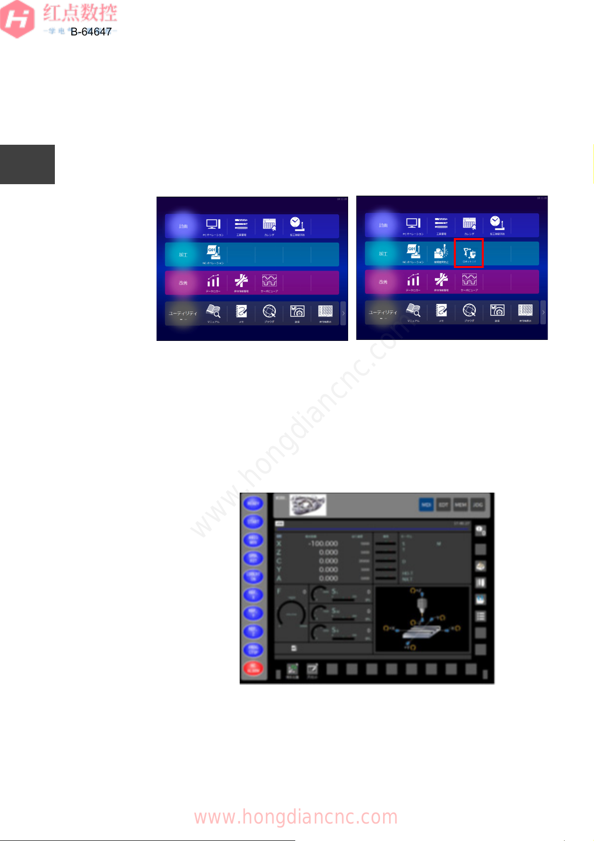
Adding an Application
You can add an application to the Home screen and start the application.
Fig. 1.1.1.2 (a) Adding an Application
In addition, the following applications can be added to the Home screen:
● Applications created with FANUC PICTURE
You can create a machine operator's panel screen using FANUC PICTURE.
Fig. 1.1.1.2 (b) Custom Screen
iHMI Home Screen customization example
www.hongdiancnc.com
www.hongdiancnc.com

CHAPTER 1 OVERVIEW
1.1 iHMI SETUP OVERVIEW
7
1
2
3
4
5
6
7
8
A1
A2
Z
B-64647EN/01
● Custom applications created using C++ or C# (user applications)
You can create a screen using the FOCAS2 library, which allows you to obtain
and set NC information, or the iHMI library, which can control iHMI applications.
Fig. 1.1.1.2 (c) User application
Registering a shortcut key
You can use the shortcut to start an application specified with the function key.
Fig. 1.1.1.2 (d) Registering a shortcut key
For details on how to customize, see "2.2 CONFIGURATION FILES THAT
AFFECT THE ENTIRE iHMI" and "3.3 CUSTOMIZING A SCREEN WITH FANUC
PICTURE".
MEMO
For the PANEL iH Pro, you can add general applications, as well as the above
applications. In addition, a small-size iHMI application can be displayed above an
application created with the display unit size.
Maintenance Manager
Display the last used
application
www.hongdiancnc.com
www.hongdiancnc.com
CHAPTER 1 OVERVIEW
1.1 iHMI SETUP OVERVIEW
8
1
2
3
4
5
6
7
8
A1
A2
Z
B-64647EN/01
1.1.2 Environment Required for iHMI Customization
1.1.2
This section describes an environment required for iHMI customization.
1.1.2.1 User application
1.1.2.1
The machine manufacturers can use the SDK and libraries when creating their
own iHMI application.
For PANEL iH Pro
To create an application that runs on the PANEL iH Pro, the following environment
is required.
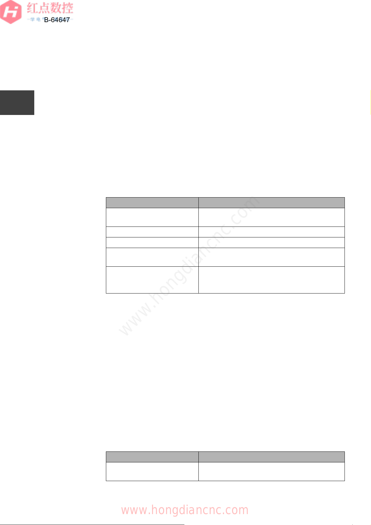
Table 1.1.2.1 (a) Environment Required to Create an Application That Runs on the
PANEL iH Pro
You can create an application using the develop languages C/C++, C#, and Visual
Basic .NET.
You can use the following libraries included in "CNC Application Development Kit"
(A08B-9010-J555#ZZ12) as necessary. The libraries can be used in Visual Studio
2008 or later.
• FOCAS2 library
• iHMI library
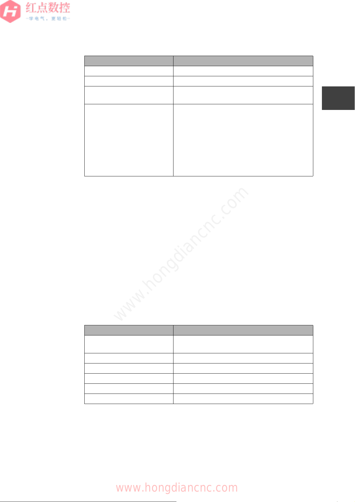
For PANEL iH
To create an application that runs on the PANEL iH, the following environment is
required.
Table 1.1.2.1 (b) Environment Required to Create an Application That Runs on
the PANEL iH
Item Description
Operating system (OS) Microsoft Windows 7 or Microsoft Windows 8
Professional
Memory 1 GB or more (2 GB or more is recommended)
Available hard disk capacity 4.7 GB or more
Display unit resolution 1024 x 768 or higher (1280 x 1024 or higher is
recommended)
Required application • Microsoft Visual Studio 2008 Professional or
Team Editions
• Microsoft Visual Studio 2008 Service Pack 1
Item Description
Operating system (OS) Microsoft Windows 7 or Microsoft Windows 8
Professional
www.hongdiancnc.com
www.hongdiancnc.com
CHAPTER 1 OVERVIEW
1.1 iHMI SETUP OVERVIEW
9
1
2
3
4
5
6
7
8
A1
A2
Z
B-64647EN/01
*1: You can create an application using the develop languages C/C++, C#, and
Visual Basic .NET included in "iHMI Application SDK for PANEL iH" (A08B-
9110-J713#ZZ11).
You can use the following libraries included in "iHMI Application SDK for PANEL
iH" (A08B-9110-J713#ZZ11) as necessary.
• Standard library (FISLIB)
• FOCAS2 library
• iHMI library
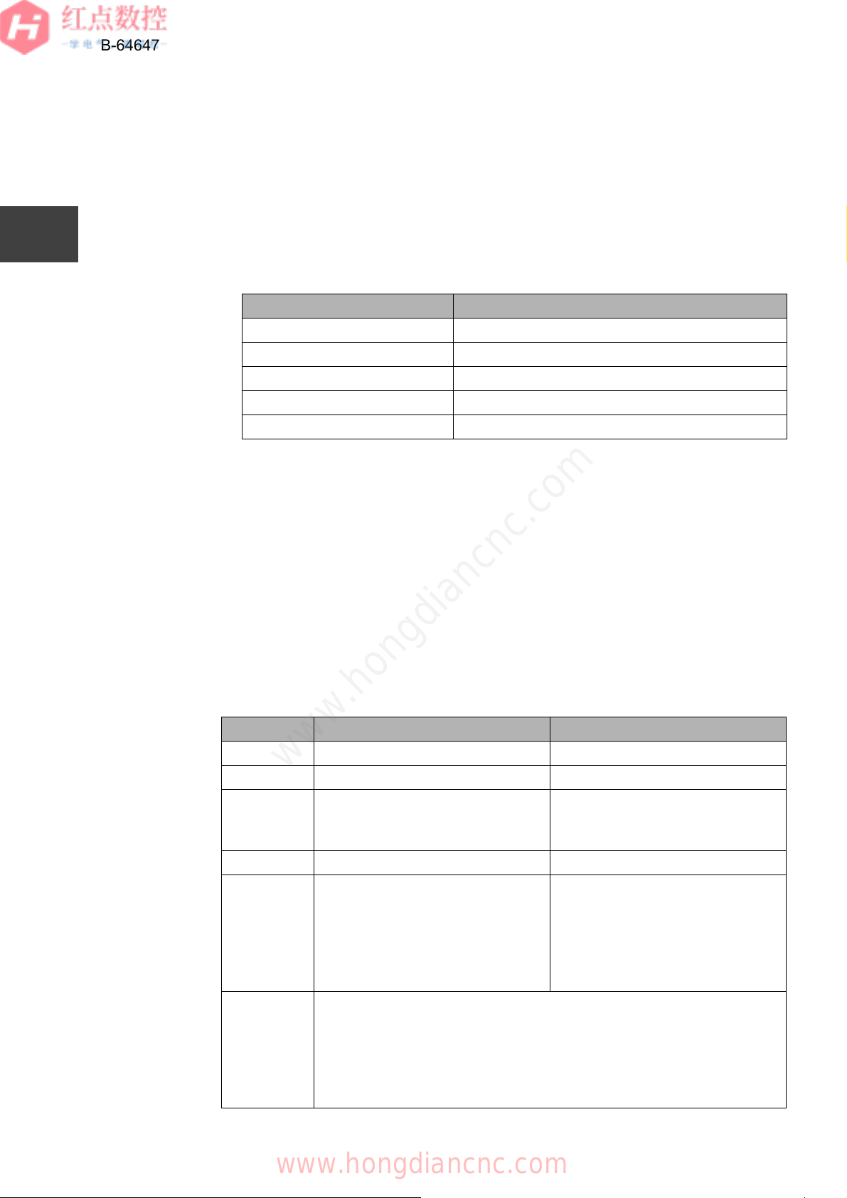
1.1.2.2 FANUC PICTURE
1.1.2.2
To create a screen using FANUC PICTURE, the following environment is required.
Table 1.1.2.2 Environment Required for FANUC PICTURE
For both PANEL iH Pro and PANEL iH, software included in "CNC Application
Development Kit" (A08B-9010-J555#ZZ12) is used to create a screen.
Memory 1 GB or more (2 GB or more is recommended)
Available hard disk capacity 4.7 GB or more
Display unit resolution 1024 x 768 or higher (1280 x 1024 or higher is
recommended)
Required application • Microsoft Visual Studio 2008 Professional or
Team Editions
• Microsoft Visual Studio 2008 Service Pack 1
• Visual Studio 2008 update for Windows
Embedded Compact 7
• Windows Embedded Compact 7 ATL Update for
Visual Studio 2008 SP1
• FANUC SDK for Windows Embedded Compact 7
(*1)
Item Description
Operating system (OS) Microsoft Windows 7, Microsoft Windows 8, or
Microsoft Windows 10
Memory 4 GB or more
Available hard disk capacity 64MB or more
Display unit resolution 1280 x 960 or higher
Peripheral device CF card, USB flash drive
Required application Internet Explorer (version 9.0 or later)
Item Description
www.hongdiancnc.com
www.hongdiancnc.com
CHAPTER 1 OVERVIEW
1.1 iHMI SETUP OVERVIEW
10
1
2
3
4
5
6
7
8
A1
A2
Z
B-64647EN/01
1.1.2.3 Machine alarm diagnosis guidance table
1.1.2.3
The machine alarm diagnosis guidance table allows you to create alarm diagnosis
function data in the iHMI Information Center. To use the machine alarm diagnosis
guidance table, the following environment is required.
Table 1.1.2.3 Environment Required for Machine Alarm Diagnosis Guidance
Table
The machine alarm diagnosis guidance table is included in both "CNC Application
Development Kit" (A08B-9010-J555#ZZ12) and "iHMI Application SDK for PANEL
iH" (A08B-9110-J713#ZZ11).
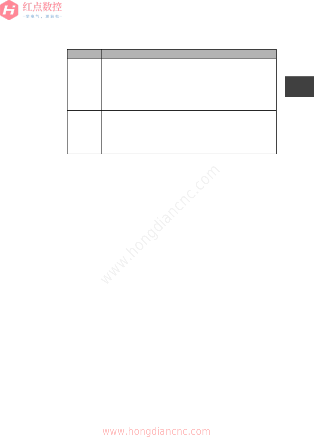
1.1.3 iHMI Hardware Performance Table
1.1.3
There are two types of hardware, FANUC PANEL iH and FANUC PANEL iH Pro.
The performance of each type is as follows:
Table 1.1.3 Performance of PANEL iH and PANEL iH Pro
Item Description
Operating system (OS) Microsoft Windows 7 or Microsoft Windows 8
Memory 1GB or more
Available hard disk capacity 128MB or more
Peripheral device CF card, USB flash drive
Required application Microsoft Excel 2007 or Microsoft Excel 2010
Item PANEL iH PANEL iH Pro
OS Windows Embedded Compact 7 Windows Embedded Standard 7
CPU ARM Core i
General
Windows
application
None Can be used after operation is
verified
Shutdown Not required Required
Memory Main memory: 1 GB
File memory: 2 to 16 GB compact
flash card
SSD type
C drive (13 GB)
D drive (All areas after C drive)
HDD type
C drive (500GB)
D drive (None)
Display 10.4 inch color TFT LCD (800 x 600),
16.0 inch color TFT LCD (1024 x 768), or
19.0 inch color TFT LCD (1280 x 1024)
32-bit full color
MDI keys (QWERTY layout, ONGP layout)
Soft keys or touch panel
www.hongdiancnc.com
www.hongdiancnc.com
CHAPTER 1 OVERVIEW
1.1 iHMI SETUP OVERVIEW
11
1
2
3
4
5
6
7
8
A1
A2
Z
B-64647EN/01
*1 Only the PC card provided by FANUC can be used.
*2 For the display integrated unit, the ports are shared with the CNC. While they
are used by the CNC, applications cannot be used.
Ports PCMCIA x 1 (*1)
Ethernet (10BASE-TX)
USB2.0 x 2
Serial port (RS-232C) x 2 (*2)
PCMCIA x 1
Ethernet (100BASE-TX)
USB2.0 x 4
Serial port (RS-232C) x 2
OS standard
software
Internet Explorer 7 for Windows
Embedded
.NET Compact Framework 3.5
Internet Explorer 8.0
Windows Media Player 12.0
.NET Framework 2.0/3.0/3.5/4.5
Software
provided by
FANUC
HSSB driver
MDI key driver
FOCAS2 library
iHMI (including the CNC screen
display function)
HSSB driver
MDI key driver
Hardware monitoring driver
FOCAS1/2 library
iHMI (including the CNC screen
display function)
Item PANEL iH PA NEL iH Pro
www.hongdiancnc.com
www.hongdiancnc.com

CHAPTER 1 OVERVIEW
1.2 iHMI MAINTENANCE OVERVIEW
12
1
2
3
4
5
6
7
8
A1
A2
Z
B-64647EN/01
1.2
The iHMI maintenance functions include the iHMI batch backup function, which
saves all data files created with the iHMI function and general data created by the
machine manufacturer or users to an external device. For details, see
"4.1 DATA
BACKUP/RESTORE".
In addition, you can update the software by updating the iHMI basic function
software. For details, see
"4.3 HOW TO UPDATE THE SOFTWARE".
1.2 iHMI MAINTENANCE OVERVIEW
www.hongdiancnc.com
www.hongdiancnc.com

1
2
3
4
5
A
2
SETTING UP
i
HMI
APPLICATIONS
This section describes how to set up each iHMI application.
2.1 iHMI APPLICATION SETUP OVERVIEW ............................................ 14
2.2 CONFIGURATION FILES THAT AFFECT THE ENTIRE iHMI ............. 17
2.3 SETTING UP BASIC FUNCTIONS ........................................................ 27
2.4 SETTING UP THE PLANNING APPLICATION...................................... 54
2.5 SETTING UP THE MACHINING APPLICATION.................................... 62
2.6 SETTING UP THE IMPROVEMENT APPLICATION............................ 159
2.7 SETTING UP THE UTILITY APPLICATION......................................... 173
2.8 CREATING PROGRAM STORAGE FILES .......................................... 181
www.hongdiancnc.com
www.hongdiancnc.com
CHAPTER 2 SETTING UP iHMI APPLICATIONS
2.1 iHMI APPLICATION SETUP OVERVIEW
14
1
2
3
4
5
6
7
8
A1
A2
Z
B-64647EN/01
2.1
You can customize the functions of iHMI applications, add applications to the
Home screen, and change the background.
2.1.1 iHMI Folder Configuration
2.1.1
iHMI application folder
iHMI applications are stored in the following locations. (These folders may be
described as "%APPPATH%" in this document.)
For PANEL iH
\Storage Card\FANUC\iHMI
For PANEL iH Pro
C:\Program Files (x86)\FANUC\iHMI
iHMI data folder
iHMI data are stored in the following locations. (These folders may be described
as "%APPDATA%" in this document.)
For PANEL iH
\Storage Card2\FANUC\iHMI
For PANEL iH Pro
For PANEL iH Pro (SSD): D:\FANUC\iHMI
For PANEL iH Pro (HDD): C:\ProgramData\FANUC\iHMI
2.1.1.1 Folder configuration inside the CNC
2.1.1.1
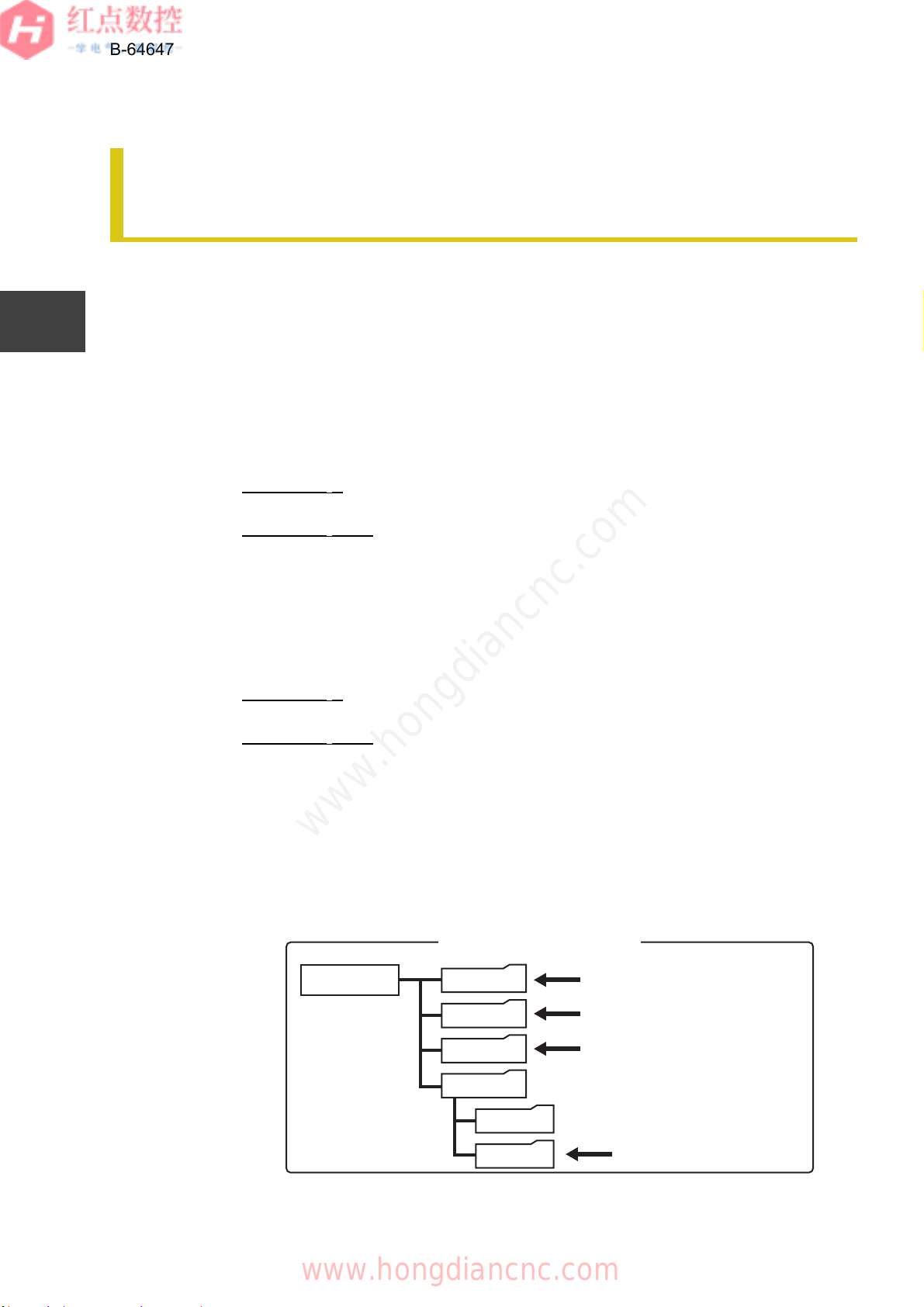
The folder configuration inside the CNC is shown below. Data required for each
customization are stored the folders (3) and (4).
Fig. 2.1.1.1 Folder configuration inside the CNC
2.1 iHMI APPLICATION SETUP OVER-
VIEW
//CNC_MEM
SYSTEM
MTB1
MTB2
USER
PATH1
LIBRARY
Program storage memory
inside the CNC
(5) System folder
(4) Folder 1 (dedicated to
machine manufacturer)
(3)Folder 2 (dedicated to
machine manufacturer)
(2) Common program
folder
www.hongdiancnc.com
www.hongdiancnc.com
Loading...