


 Loading...
UserManual
ProductModel: |
|
TM DGS-3400Series |
|
Layer2GigabitEthernetManagedSwitch
Release2.35
i

xStack DGS-3400 Series Layer 2 Gigabit Ethernet Managed Switch
_____________________________________________
Information in this document is subject to change without notice. © 2008 D-Link Computer Corporation. All rights reserved.
Reproduction in any manner whatsoever without the written permission of D-Link Computer Corporation is strictly forbidden.
Trademarks used in this text: D-Link and the D-LINK logo are trademarks of D-Link Computer Corporation; Microsoft and Windows are registered trademarks of Microsoft Corporation.
Other trademarks and trade names may be used in this document to refer to either the entities claiming the marks and names or their products. D-Link Computer Corporation disclaims any proprietary interest in trademarks and trade names other than its own.
August 2008 P/N 651GS3400065G
ii

|
Table of Contents |
Intended Readers............................................................................................................................................................................ |
x |
Typographical Conventions ............................................................................................................................................................................ |
x |
Notes, Notices, and Cautions ........................................................................................................................................................ |
xi |
Safety Instructions........................................................................................................................................................................ |
xii |
Safety Cautions ............................................................................................................................................................................................ |
xii |
General Precautions for Rack-Mountable Products .................................................................................................................................... |
xiii |
Lithium Battery Precaution..................................................................................................................................................................... |
xiv |
Protecting Against Electrostatic Discharge.................................................................................................................................................. |
xiv |
Introduction...................................................................................................................................................... |
1 |
Switch Description..................................................................................................................................................................................... |
1 |
Features........................................................................................................................................................................................................... |
2 |
Ports ................................................................................................................................................................................................................ |
3 |
Front-Panel Components ........................................................................................................................................................................... |
4 |
LED Indicators................................................................................................................................................................................................ |
5 |
Rear Panel Description .............................................................................................................................................................................. |
7 |
Side Panel Description............................................................................................................................................................................... |
8 |
Installation........................................................................................................................................................ |
9 |
Package Contents....................................................................................................................................................................................... |
9 |
Installation Guidelines ............................................................................................................................................................................... |
9 |
Installing the Switch without the Rack .................................................................................................................................................... |
10 |
Installing the Switch in a Rack ................................................................................................................................................................ |
10 |
Mounting the Switch in a Standard 19" Rack .......................................................................................................................................... |
11 |
Power On ...................................................................................................................................................................................................... |
11 |
Power Failure........................................................................................................................................................................................... |
11 |
Installing the SFP ports............................................................................................................................................................................ |
12 |
The Optional Module .................................................................................................................................................................................... |
13 |
Installing the Module............................................................................................................................................................................... |
14 |
External Redundant Power System ............................................................................................................................................................... |
15 |
Connecting the Switch ................................................................................................................................... |
17 |
Switch to End Node ................................................................................................................................................................................. |
17 |
Switch to Switch...................................................................................................................................................................................... |
17 |
Connecting To Network Backbone or Server ............................................................................................................................................... |
18 |
Introduction to Switch Management ........................................................................................................... |
19 |
Management Options............................................................................................................................................................................... |
19 |
Connecting the Console Port (RS-232 DCE)........................................................................................................................................... |
20 |
Managing the Switch for the First Time .................................................................................................................................................. |
21 |
Password Protection................................................................................................................................................................................. |
22 |
IP Address Assignment............................................................................................................................................................................ |
24 |
Web-based Switch Configuration................................................................................................................. |
26 |
Introduction.................................................................................................................................................................................. |
26 |
Logging in to the Web Manager ................................................................................................................................................................... |
26 |
Web-based User Interface ............................................................................................................................................................................. |
27 |
Areas of the User Interface ...................................................................................................................................................................... |
27 |
Web Pages..................................................................................................................................................................................................... |
28 |
Configuring the Switch.................................................................................................................................. |
30 |
Device Information ...................................................................................................................................................................... |
31 |
IPv6.............................................................................................................................................................................................. |
33 |
Overview....................................................................................................................................................................................................... |
33 |
Packet Format ............................................................................................................................................................................................... |
34 |
IPv6 Header ............................................................................................................................................................................................. |
34 |
Extension Headers ................................................................................................................................................................................... |
35 |
Packet Fragmentation .............................................................................................................................................................................. |
35 |
Address Format............................................................................................................................................................................................. |
35 |
Types ....................................................................................................................................................................................................... |
36 |
ICMPv6......................................................................................................................................................................................................... |
37 |
Neighbor Discovery ...................................................................................................................................................................................... |
37 |
Neighbor Unreachability Detection ......................................................................................................................................................... |
37 |
Duplicate Address Detection (DAD) ....................................................................................................................................................... |
38 |
Assigning IP Addresses ........................................................................................................................................................................... |
38 |
IP Interface Setup .................................................................................................................................................................................... |
38 |
IP Address.................................................................................................................................................................................... |
39 |
Setting the Switch's IP Address using the Console Interface ................................................................................................................... |
40 |
Interface Settings.......................................................................................................................................................................... |
41 |
IPv4 Interface Settings............................................................................................................................................................................. |
41 |
IPv6 Interface Settings............................................................................................................................................................................. |
42 |
Stacking........................................................................................................................................................................................ |
46 |
Stack Switch Swapping ........................................................................................................................................................................... |
47 |
Stacking Mode Settings ........................................................................................................................................................................... |
48 |
Box Information....................................................................................................................................................................................... |
48 |
Port Configuration........................................................................................................................................................................ |
49 |
Port Error Disabled .................................................................................................................................................................................. |
50 |
Port Description....................................................................................................................................................................................... |
51 |
Cable Diagnostics .................................................................................................................................................................................... |
51 |
User Accounts .............................................................................................................................................................................. |
53 |
Port Mirroring .............................................................................................................................................................................. |
54 |
Mirroing within the Switch Stack ............................................................................................................................................................ |
55 |
System Log .................................................................................................................................................................................. |
56 |
System Log Save Mode Settings ............................................................................................................................................................. |
57 |
System Severity Settings.............................................................................................................................................................. |
59 |
SNTP Settings.............................................................................................................................................................................. |
60 |
Time Settings........................................................................................................................................................................................... |
60 |
Time Zone and DST...................................................................................................................................................................................... |
61 |
MAC Notification Settings .......................................................................................................................................................... |
63 |
TFTP Services.............................................................................................................................................................................. |
64 |
Multiple Image Services .............................................................................................................................................................. |
66 |
Firmware Information.............................................................................................................................................................................. |
66 |
Config Firmware Image........................................................................................................................................................................... |
67 |
Ping Test ...................................................................................................................................................................................... |
68 |
IPv4 Ping Test ......................................................................................................................................................................................... |
68 |
IPv6 Ping Test ......................................................................................................................................................................................... |
69 |
Safeguard Engine ......................................................................................................................................................................... |
70 |
Static ARP Settings...................................................................................................................................................................... |
72 |
IPv6 Neighbor .............................................................................................................................................................................. |
73 |
IPv6 Neighbor Settings............................................................................................................................................................................ |
73 |
Routing Table............................................................................................................................................................................... |
75 |
IPv4 Static/Default Route Settings................................................................................................................................................................ |
75 |
IPv6 Static/Default Route Settings................................................................................................................................................................ |
76 |
DHCP/BOOTP Relay................................................................................................................................................................... |
78 |
DHCP / BOOTP Relay Global Settings ........................................................................................................................................................ |
78 |
The Implementation of DHCP Information Option 82 ............................................................................................................................ |
80 |
DHCP/BOOTP Relay Interface Settings....................................................................................................................................................... |
81 |
DHCP Auto Configuration Settings............................................................................................................................................. |
82 |
SNMP Manager............................................................................................................................................................................ |
83 |
SNMP Trap Settings ................................................................................................................................................................................ |
84 |
SNMP User Table.................................................................................................................................................................................... |
84 |
SNMP View Table................................................................................................................................................................................... |
86 |
SNMP Group Table ................................................................................................................................................................................. |
87 |
SNMP Community Table ........................................................................................................................................................................ |
89 |
SNMP Host Table.................................................................................................................................................................................... |
90 |
SNMP Engine ID..................................................................................................................................................................................... |
91 |
IP-MAC-Port Binding.................................................................................................................................................................. |
92 |
ACL Mode .................................................................................................................................................................................................... |
92 |
IP-MAC Binding Port ................................................................................................................................................................................... |
94 |
IP-MAC Binding Table................................................................................................................................................................................. |
95 |
IP-MAC Binding Blocked............................................................................................................................................................................. |
96 |
PoE Configuration........................................................................................................................................................................ |
97 |
PoE System Settings ..................................................................................................................................................................................... |
97 |
PoE Port Settings .......................................................................................................................................................................................... |
99 |
Single IP Management (SIM) Overview.................................................................................................................................... |
101 |
The Upgrade to v1.61 ............................................................................................................................................................................ |
102 |
Single IP vs. Switch Stacking ................................................................................................................................................................ |
103 |
SIM Using the Web Interface ................................................................................................................................................................ |
103 |
Topology..................................................................................................................................................................................................... |
104 |
Tool Tips ............................................................................................................................................................................................... |
107 |
Menu Bar ............................................................................................................................................................................................... |
111 |
Firmware Upgrade ...................................................................................................................................................................................... |
112 |
Configuration Backup/Restore.................................................................................................................................................................... |
112 |
Upload Log ................................................................................................................................................................................................. |
113 |
Layer 2 Features .......................................................................................................................................... |
114 |
VLANs........................................................................................................................................................................................................ |
114 |
Understanding IEEE 802.1p Priority ..................................................................................................................................................... |
114 |
VLAN Description...................................................................................................................................................................................... |
114 |
Notes about VLANs on the DGS-3400 Series....................................................................................................................................... |
115 |
IEEE 802.1Q VLANs ................................................................................................................................................................................. |
115 |
802.1Q VLAN Tags............................................................................................................................................................................... |
116 |
Port VLAN ID ....................................................................................................................................................................................... |
117 |
Tagging and Untagging ......................................................................................................................................................................... |
117 |
Ingress Filtering..................................................................................................................................................................................... |
118 |
Default VLANs...................................................................................................................................................................................... |
118 |
Port-based VLANs................................................................................................................................................................................. |
118 |
VLAN Segmentation ............................................................................................................................................................................. |
119 |
VLAN and Trunk Groups ...................................................................................................................................................................... |
119 |
Protocol VLANs .................................................................................................................................................................................... |
119 |
Static VLAN Entry ..................................................................................................................................................................................... |
119 |
GVRP Settings............................................................................................................................................................................................ |
123 |
Double VLANs ........................................................................................................................................................................................... |
124 |
Regulations for Double VLANs ............................................................................................................................................................ |
125 |
Double VLAN............................................................................................................................................................................................. |
126 |
PVID Auto Assign ...................................................................................................................................................................................... |
128 |
MAC-based VLAN Settings ....................................................................................................................................................................... |
129 |
Trunking..................................................................................................................................................................................... |
130 |
Understanding Port Trunk Groups......................................................................................................................................................... |
130 |
Link Aggregation ........................................................................................................................................................................................ |
131 |
LACP Port Settings..................................................................................................................................................................................... |
134 |
IGMP Snooping ......................................................................................................................................................................... |
137 |
IGMP Snooping Settings ............................................................................................................................................................................ |
137 |
Router Port Settings .................................................................................................................................................................................... |
138 |
ISM VLAN ................................................................................................................................................................................................. |
140 |
Restrictions and Provisos....................................................................................................................................................................... |
140 |
Limited Multicast Address Range............................................................................................................................................................... |
142 |
MLD Snooping .......................................................................................................................................................................... |
144 |
MLD Control Messages......................................................................................................................................................................... |
144 |
MLD Snooping Settings.............................................................................................................................................................................. |
144 |
MLD Router Port Settings .......................................................................................................................................................................... |
146 |
Loopback Detection Global Settings.......................................................................................................................................... |
148 |
Spanning Tree ............................................................................................................................................................................ |
150 |
802.1s MSTP ......................................................................................................................................................................................... |
150 |
802.1w Rapid Spanning Tree................................................................................................................................................................. |
150 |
Port Transition States............................................................................................................................................................................. |
150 |
Edge Port ............................................................................................................................................................................................... |
151 |
P2P Port ................................................................................................................................................................................................. |
151 |
802.1D/802.1w/802.1s Compatibility.................................................................................................................................................... |
151 |
STP Bridge Global Settings ........................................................................................................................................................................ |
152 |
MST Configuration Identification............................................................................................................................................................... |
155 |
MSTP Port Information .............................................................................................................................................................................. |
157 |
STP Instance Settings.................................................................................................................................................................................. |
159 |
STP Port Settings ........................................................................................................................................................................................ |
160 |
Forwarding & Filtering .............................................................................................................................................................. |
162 |
Unicast Forwarding..................................................................................................................................................................................... |
162 |
Multicast Forwarding.................................................................................................................................................................................. |
162 |
Multicast Filtering Mode............................................................................................................................................................................. |
163 |
QoS ................................................................................................................................................................ |
165 |
QoS ............................................................................................................................................................................................................. |
165 |
The Advantages of QoS .............................................................................................................................................................................. |
165 |
Understanding QoS................................................................................................................................................................................ |
166 |
Bandwidth Control...................................................................................................................................................................................... |
168 |
QoS Scheduling Mechanism ....................................................................................................................................................................... |
169 |
QoS Output Scheduling .............................................................................................................................................................................. |
170 |
Configuring the Combination Queue..................................................................................................................................................... |
171 |
802.1P Default Priority ............................................................................................................................................................................... |
172 |
802.1P User Priority.................................................................................................................................................................................... |
173 |
ACL (Access Control List) .......................................................................................................................... |
174 |
Time Range................................................................................................................................................................................ |
174 |
Access Profile Table .................................................................................................................................................................. |
176 |
CPU Interface Filtering.............................................................................................................................................................. |
189 |
CPU Interface Filtering State Settings ........................................................................................................................................................ |
189 |
CPU Interface Filtering Table..................................................................................................................................................................... |
189 |
Security ......................................................................................................................................................... |
202 |
Authorization Network State Settings........................................................................................................................................ |
202 |
Traffic Control ........................................................................................................................................................................... |
203 |
Port Security............................................................................................................................................................................... |
205 |
Port Security Entries ................................................................................................................................................................................... |
206 |
802.1X........................................................................................................................................................................................ |
207 |
Guest VLANs.............................................................................................................................................................................................. |
212 |
Limitations Using the Guest VLAN ...................................................................................................................................................... |
212 |
Configure 802.1X Authenticator................................................................................................................................................................. |
213 |
Configure 802.1x Guest VLAN .................................................................................................................................................................. |
215 |
Authentic RADIUS Server.......................................................................................................................................................................... |
216 |
Trust Host................................................................................................................................................................................... |
217 |
Access Authentication Control................................................................................................................................................... |
218 |
Authentication Policy & Parameters ........................................................................................................................................................... |
219 |
Application's Authentication Settings ......................................................................................................................................................... |
219 |
Authentication Server Group ...................................................................................................................................................................... |
220 |
Authentication Server Host ......................................................................................................................................................................... |
221 |
Login Method Lists..................................................................................................................................................................................... |
223 |
Enable Method Lists ................................................................................................................................................................................... |
224 |
Configure Local Enable Password .............................................................................................................................................................. |
227 |
Enable Admin ............................................................................................................................................................................................. |
227 |
MAC Based Access Control ...................................................................................................................................................... |
228 |
MAC Based Access Control Global Settings.............................................................................................................................................. |
228 |
MAC Based Access Control Local MAC Settings...................................................................................................................................... |
229 |
Traffic Segmentation.................................................................................................................................................................. |
231 |
Secure Socket Layer (SSL) ........................................................................................................................................................ |
232 |
Download Certificate .................................................................................................................................................................................. |
232 |
SSL Configuration ...................................................................................................................................................................................... |
233 |
Secure Shell (SSH)..................................................................................................................................................................... |
235 |
SSH Server Configuration........................................................................................................................................................................... |
235 |
SSH Authentication Mode .......................................................................................................................................................................... |
236 |
SSH User Authentication Mode.................................................................................................................................................................. |
238 |
JWAC (Japanese Web-based Access Control)........................................................................................................................... |
240 |
JWAC Global Configuration....................................................................................................................................................................... |
240 |
JWAC Port Settings .................................................................................................................................................................................... |
242 |
JWAC User Account................................................................................................................................................................................... |
245 |
JWAC Host Information ............................................................................................................................................................................. |
246 |
Monitoring.................................................................................................................................................... |
247 |
Device Status.............................................................................................................................................................................. |
248 |
Stacking Information.................................................................................................................................................................. |
248 |
Module Information ................................................................................................................................................................... |
249 |
CPU Utilization.......................................................................................................................................................................... |
250 |
Port Utilization........................................................................................................................................................................... |
251 |
Packets ....................................................................................................................................................................................... |
252 |
Received (Rx) ........................................................................................................................................................................................ |
252 |
UMB Cast (RX)..................................................................................................................................................................................... |
254 |
Transmitted (TX) ................................................................................................................................................................................... |
256 |
Errors.......................................................................................................................................................................................... |
258 |
Received (RX) ....................................................................................................................................................................................... |
258 |
Transmitted (TX) ................................................................................................................................................................................... |
260 |
Packet Size ................................................................................................................................................................................. |
262 |
Browse Router Port.................................................................................................................................................................... |
265 |
Browse MLD Router Port .......................................................................................................................................................... |
266 |
VLAN Status.............................................................................................................................................................................. |
267 |
VLAN Status Port ...................................................................................................................................................................... |
268 |
Port Access Control.................................................................................................................................................................... |
269 |
RADIUS Authentication ............................................................................................................................................................................. |
269 |
RADIUS Account Client............................................................................................................................................................................. |
270 |
MAC Address Table .................................................................................................................................................................. |
272 |
IGMP Snooping Group .............................................................................................................................................................. |
273 |
MLD Snooping Group ............................................................................................................................................................... |
274 |
Switch Logs................................................................................................................................................................................ |
275 |
Browse ARP Table..................................................................................................................................................................... |
276 |
Session Table ............................................................................................................................................................................. |
277 |
IP Forwarding Table .................................................................................................................................................................. |
278 |
Browse Routing Table................................................................................................................................................................ |
279 |
MAC Based Access Control Authentication Status |
................................................................................................................... 280 |
Save, Reset and Reboot................................................................................................................................ |
281 |
Reset........................................................................................................................................................................................... |
281 |
Reboot System ........................................................................................................................................................................... |
282 |
Save Services ............................................................................................................................................................................. |
283 |
Save Changes.............................................................................................................................................................................................. |
283 |
Configuration Information .......................................................................................................................................................................... |
284 |
Current Configuration Settings ................................................................................................................................................................... |
285 |
Logout ........................................................................................................................................................................................ |
285 |
Appendix A................................................................................................................................................... |
286 |
Technical Specifications ............................................................................................................................................................................. |
286 |
Appendix B ................................................................................................................................................... |
288 |
Cables and Connectors................................................................................................................................................................................ |
288 |
Appendix C................................................................................................................................................... |
289 |
Cable Lengths ............................................................................................................................................................................................. |
289 |
Appendix D................................................................................................................................................... |
290 |
Switch Log Entries...................................................................................................................................................................................... |
290 |
Glossary ........................................................................................................................................................ |
302 |
Warranties/Registration.............................................................................................................................. |
304 |
Technical Support........................................................................................................................................ |
313 |
International Offices.................................................................................................................................... |
340 |

xStack DGS-3400 Series Layer 2 Gigabit Ethernet Managed Switch
Intended Readers
The xStack DGS-3400 series Manual contains information for setup and management of the Switch. This manual is intended for network managers familiar with network management concepts and terminology.
Typographical Conventions
Convention |
Description |
[ ]
Bold font
Boldface Typewriter
Font
Initial capital letter
Italics
Menu Name > Menu
Option
In a command line, square brackets indicate an optional entry. For example: [copy filename] means that optionally you can type copy followed by the name of the file. Do not type the brackets.
Indicates a button, a toolbar icon, menu, or menu item. For example: Open the File menu and choose Cancel. Used for emphasis. May also indicate system messages or prompts appearing on screen. For example: You have mail. Bold font is also used to represent filenames, program names and commands. For example: use the copy command.
Indicates commands and responses to prompts that must be typed exactly as printed in the manual.
Indicates a window name. Names of keys on the keyboard have initial capitals. For example: Click Enter.
Indicates a window name or a field. Also can indicate a variables or parameter that is replaced with an appropriate word or string. For example: type filename means that the actual filename should be typed instead of the word shown in italic.
Menu Name > Menu Option Indicates the menu structure. Device > Port > Port Properties means the Port Properties menu option under the Port menu option that is located under the Device menu.
x
xStack DGS-3400 Series Layer 2 Gigabit Ethernet Managed Switch
Notes, Notices, and Cautions
A NOTE indicates important information that helps make better use of the device.
A NOTICE indicates either potential damage to hardware or loss of data and tells how to avoid the problem.
A CAUTION indicates a potential for property damage, personal injury, or death.
xi

xStack DGS-3400 Series Layer 2 Gigabit Ethernet Managed Switch
Safety Instructions
Use the following safety guidelines to ensure your own personal safety and to help protect your system from potential damage.
Throughout this safety section, the caution icon (  ) is used to indicate cautions and precautions that need to be reviewed and followed.
Safety Cautions
To reduce the risk of bodily injury, electrical shock, fire, and damage to the equipment, observe the following precautions.
•Observe and follow service markings.
•Do not service any product except as explained in the system documentation.
•Opening or removing covers that are marked with the triangular symbol with a lightning bolt may expose the user to electrical shock.
•Only a trained service technician should service components inside these compartments.
•If any of the following conditions occur, unplug the product from the electrical outlet and replace the part or contact your trained service provider:
•Damage to the power cable, extension cable, or plug.
•An object has fallen into the product.
•The product has been exposed to water.
•The product has been dropped or damaged.
•The product does not operate correctly when the operating instructions are correctly followed.
•Keep your system away from radiators and heat sources. Also, do not block cooling vents.
•Do not spill food or liquids on system components, and never operate the product in a wet environment. If the system gets wet, see the appropriate section in the troubleshooting guide or contact your trained service provider.
•Do not push any objects into the openings of the system. Doing so can cause fire or electric shock by shorting out interior components.
•Use the product only with approved equipment.
•Allow the product to cool before removing covers or touching internal components.
•Operate the product only from the type of external power source indicated on the electrical ratings label. If unsure of the type of power source required, consult your service provider or local power company.
•To help avoid damaging the system, be sure the voltage selection switch (if provided) on the power supply is set to match the power available at the Switch’s location:
•115 volts (V)/60 hertz (Hz) in most of North and South America and some Far Eastern countries such as South Korea and Taiwan
•100 V/50 Hz in eastern Japan and 100 V/60 Hz in western Japan
•230 V/50 Hz in most of Europe, the Middle East, and the Far East
•Also, be sure that attached devices are electrically rated to operate with the power available in your location.
•Use only approved power cable(s). If you have not been provided with a power cable for your system or for any ACpowered option intended for your system, purchase a power cable that is approved for use in your country. The power cable must be rated for the product and for the voltage and current marked on the product's electrical ratings label. The voltage and current rating of the cable should be greater than the ratings marked on the product.
•To help prevent electric shock, plug the system and peripheral power cables into properly grounded electrical outlets. These cables are equipped with three-prong plugs to help ensure proper grounding. Do not use adapter plugs or remove the grounding prong from a cable. If using an extension cable is necessary, use a 3-wire cable with properly grounded plugs.
xii

xStack DGS-3400 Series Layer 2 Gigabit Ethernet Managed Switch
•Observe extension cable and power strip ratings. Make sure that the total ampere rating of all products plugged into the extension cable or power strip does not exceed 80 percent of the ampere ratings limit for the extension cable or power strip.
•To help protect the system from sudden, transient increases and decreases in electrical power, use a surge suppressor, line conditioner, or uninterruptible power supply (UPS).
•Position system cables and power cables carefully; route cables so that they cannot be stepped on or tripped over. Be sure that nothing rests on any cables.
•Do not modify power cables or plugs. Consult a licensed electrician or your power company for site modifications. Always follow your local/national wiring rules.
•When connecting or disconnecting power to hot-pluggable power supplies, if offered with your system, observe the following guidelines:
•Install the power supply before connecting the power cable to the power supply.
•Unplug the power cable before removing the power supply.
•If the system has multiple sources of power, disconnect power from the system by unplugging all power cables from the power supplies.
•Move products with care; ensure that all casters and/or stabilizers are firmly connected to the system. Avoid sudden stops and uneven surfaces.
General Precautions for Rack-Mountable Products
Observe the following precautions for rack stability and safety. Also, refer to the rack installation documentation accompanying the system and the rack for specific caution statements and procedures.
•Systems are considered to be components in a rack. Thus, "component" refers to any system as well as to various peripherals or supporting hardware.
CAUTION: Installing systems in a rack without the front and side stabilizers installed could cause the rack to tip over, potentially resulting in bodily injury under certain circumstances. Therefore, always install the stabilizers before installing components in the rack. After installing system/components in a rack, never pull more than one component out of the rack on its slide assemblies at one time. The weight of more than one extended component could cause the rack to tip over and may result in serious injury.
•Before working on the rack, make sure that the stabilizers are secured to the rack, extended to the floor, and that the full weight of the rack rests on the floor. Install front and side stabilizers on a single rack or front stabilizers for joined multiple racks before working on the rack.
•Always load the rack from the bottom up, and load the heaviest item in the rack first.
•Make sure that the rack is level and stable before extending a component from the rack.
•Use caution when pressing the component rail release latches and sliding a component into or out of a rack; the slide rails can pinch your fingers.
•After a component is inserted into the rack, carefully extend the rail into a locking position, and then slide the component into the rack.
•Do not overload the AC supply branch circuit that provides power to the rack. The total rack load should not exceed 80 percent of the branch circuit rating.
•Ensure that proper airflow is provided to components in the rack.
•Do not step on or stand on any component when servicing other components in a rack.
xiii

xStack DGS-3400 Series Layer 2 Gigabit Ethernet Managed Switch
NOTE: A qualified electrician must perform all connections to DC power and to safety grounds. All electrical wiring must comply with applicable local or national codes and practices.
CAUTION: Never defeat the ground conductor or operate the equipment in the absence of a suitably installed ground conductor. Contact the appropriate electrical inspection authority or an electrician if uncertain that suitable grounding is available.
CAUTION: The system chassis must be positively grounded to the rack cabinet frame. Do not attempt to connect power to the system until grounding cables are connected. Completed power and safety ground wiring must be inspected by a qualified electrical inspector. An energy hazard will exist if the safety ground cable is omitted or disconnected.
Lithium Battery Precaution
CAUTION: Incorrectly replacing the lithium battery of the Switch may cause the battery to explode. Replace this battery only with the same or equivalent type recommended by the manufacturer. Discard used batteries according to the manufacturers instructions.
Protecting Against Electrostatic Discharge
Static electricity can harm delicate components inside the system. To prevent static damage, discharge static electricity from your body before touching any of the electronic components, such as the microprocessor. This can be done by periodically touching an unpainted metal surface on the chassis.
The following steps can also be taken prevent damage from electrostatic discharge (ESD):
1.When unpacking a static-sensitive component from its shipping carton, do not remove the component from the antistatic packing material until ready to install the component in the system. Just before unwrapping the antistatic packaging, be sure to discharge static electricity from your body.
2.When transporting a sensitive component, first place it in an antistatic container or packaging.
3.Handle all sensitive components in a static-safe area. If possible, use antistatic floor pads, workbench pads and an antistatic grounding strap.
xiv

xStack DGS-3400 Series Layer 2 Gigabit Ethernet Managed Switch
Section 1
Introduction
Ethernet Technology
Switch Description
Features
Ports
Front-Panel Components
Side Panel Description
Rear Panel Description
Gigabit Combo Ports
Ethernet Technology
Fast Ethernet Technology
The DGS-3400 Gigabit Ethernet switches are members of the D-Link xStack family. Ranging from 10/100Mbps edge switches to core gigabit switches, the xStack switch family has been future-proof designed to deliver a system with fault tolerance, flexibility, port density, robust security and maximum throughput with a user-friendly management interface for the networking professional.
This manual describes the installation, maintenance and configurations concerning members of the xStack DGS-3400 Switch Series. These switches include: the DGS-3426, DGS-3426P, DGS-3427 and the DGS-3450. The xStack DGS-3400 Series switches are similar in configurations and basic hardware and consequentially, most of the information in this manual will be universal to the whole xStack DGS-3400 Series. Corresponding screen pictures of the web manager may be taken from any one of these switches but the configuration will be identical, except for varying port counts.
Switch Description
D-Link's next-generation xStack DGS-3400 Series switches are high port-density stackable switches that combine the ultimate performance with fault tolerance, security, management functions with flexibility and ease-of-use. All these features, typically found in the more expensive chassis-based solutions, are available from the xStack DGS-3400 switch series at the price of a stackable switch!
All xStack DGS-3400 Series switches have some combination of 1000BASE-T ports, SFP ports and 10-Gigabit ports that may be used in uplinking various network devices to the Switch, including PCs, hubs and other switches to provide a gigabit Ethernet uplink in full-duplex mode. The SFP (Small Form Factor Portable) combo ports are used with fiber-optical transceiver cabling in order to uplink various other networking devices for a gigabit link that may span great distances. These SFP ports support fullduplex transmissions, have auto-negotiation and can be used with DEM-310GT (1000BASE-LX), DEM-311GT (1000BASE-SX), DEM-314GT (1000BASE-LH), DEM-312GT2 (100BASE-SX) and DEM-315GT (1000BASE-ZX) transceivers. Users may also use one of the WDM Single Mode Transceivers, such as the DEM-330T/R or the DEM-331T/R. The rear panel of the xStack DGS-3400 Switches Series includes spaces for optional single-port module inserts for single port 10GE XFP or 10GBASE-CX4 modules used for backbone uplink or stacking connection to another xStack DGS-3400 Series Switch.
1

xStack DGS-3400 Series Layer 2 Gigabit Ethernet Managed Switch
Features
The list of features below highlights the significant features of the xStack DGS-3400 Series.
•IEEE 802.3z compliant
•IEEE 802.3x Flow Control in full-duplex compliant
•IEEE 802.3u compliant
•IEEE 802.3ab compliant
•IEEE 802.3ae compliant (for optional XFP module)
•IEEE 802.1p Priority Queues
•IEEE 802.3ad Link Aggregation Control Protocol support.
•IEEE 802.1X Port-based and MAC-based Access Control
•IEEE 802.1Q VLAN
•IEEE 802.1D Spanning Tree, IEEE 802.1W Rapid Spanning Tree and IEEE 802.1s Multiple Spanning Tree support
•IEEE 802.3af Power-over-Ethernet support for the DGS-3426P
•Stacking support in either Duplex-Ring or Duplex-Chain topology
•Access Control List (ACL) support
•IP Multinetting support
•Protocol VLAN support
•Single IP Management support
•Access Authentication Control utilizing TACACS, XTACACS, TACACS+ and RADIUS protocols
•Dual Image Firmware
•Simple Network Time Protocol support
•MAC Notification support
•System and Port Utilization support
•System Log Support
•High performance switching engine performs forwarding and filtering at full wire speed up to 128Gbps.
•Fulland half-duplex for all gigabit ports. Full duplex allows the switch port to simultaneously transmit and receive data. It only works with connections to full-duplex-capable end stations and switches. Connections to a hub must take place at halfduplex.
•Support broadcast storm filtering
•Non-blocking store and forward switching scheme capability to support rate adaptation and protocol conversion
•Supports by-port Egress/Ingress rate control
•Efficient self-learning and address recognition mechanism enables forwarding rate at wire speed
•Support port-based enable and disable
•Address table: Supports up to 8K MAC addresses per device
•Supports a packet buffer of up to 3 Mbits
•Port Trunking with flexible load distribution and fail-over function
•IGMP Snooping support
•MLD Snooping support (MLD v1 and v2)
•SNMP support
•Secure Sockets Layer (SSL) and Secure Shell (SSH) support
2

xStack DGS-3400 Series Layer 2 Gigabit Ethernet Managed Switch
•System Severity control
•Port Mirroring support
•MIB support for:
•RFC1213 MIB II
•RFC1493 Bridge
•RFC1757 RMON
•RFC1643 Ether-like MIB
•RFC2233 Interface MIB
•IF MIB
•Private MIB
•RFC2674 for 802.1p
•IEEE 802.1X MIB
•RS-232 DCE console port for Switch management
•Provides parallel LED display for port status such as link/act, speed, etc.
•PoE Support for the DGS-3426P
•IPv6 Support
Ports
The xStack DGS-3400 Series switches port options, as listed by device.
DGS-3426
•Twenty-four 10/100/1000BASE-T Gigabit ports
•Four Combo SFP Ports
•Two slots open for single port 10GE XFP or 10GBASE-CX4 modules
•One RS-232 DB-9 console port
|
DGS-3426P |
|
DGS-3427 |
|
DGS-3450 |
|
• |
Twenty-four PoE |
• |
Twenty-four |
• |
Forty-eight |
|
|
Compliant |
|
10/100/1000BASE-T |
|
10/100/1000BASE-T |
|
|
10/100/1000BASE-T |
|
Gigabit ports |
|
Gigabit ports |
|
|
Gigabit ports |
• Four Combo SFP Ports |
• Four Combo SFP Ports |
|||
• |
Four Combo SFP Ports |
|||||
• |
Three slots open for |
• Two slots open for |
||||
• Two slots open for |
|
single port 10GE XFP |
|
single port 10GE XFP |
||
|
single port 10GE XFP |
|
or 10GBASE-CX4 |
|
or 10GBASE-CX4 |
|
|
or 10GBASE-CX4 |
|
modules |
|
modules |
|
|
modules |
• |
One RS-232 DB-9 |
• |
One RS-232 DB-9 |
|
• |
|
|||||
One RS-232 DB-9 |
|
console port |
|
console port |
||
|
console port |
|
|
|
|
|
NOTE: For customers interested in D-View, D-Link Corporation's proprietary SNMP management software, go to the D-Link Website and download the software and manual.
3

xStack DGS-3400 Series Layer 2 Gigabit Ethernet Managed Switch
Front-Panel Components
The front panel of the Switch consists of LED indicators for Power, Master, Console, RPS, and for Link/Act for each port on the Switch including 10GE Ports for optional modules and SFP port LEDs. The front panel includes a seven-segment LED indicating the Stack ID number. A separate table below describes LED indicators in more detail. DGS-3426P also includes a Mode Select button for changing the mode Link/Act/State to PoE.
DGS-3426
Figure 2- 1. Front Panel View of the DGS-3426 as shipped
DGS-3426P
Figure 2- 2. Front Panel View of the DGS-3426P as shipped
DGS-3427
Figure 2- 3. Front Panel View of the DGS-3427 as shipped
DGS-3450
Figure 2- 4. Front Panel View of the DGS-3450 as shipped
4
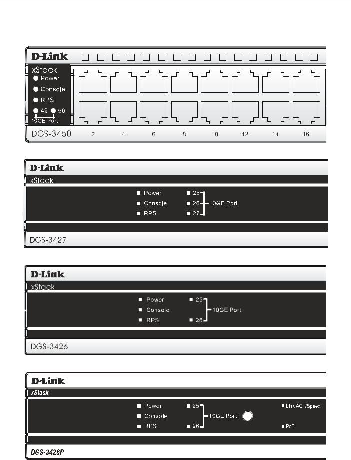
xStack DGS-3400 Series Layer 2 Gigabit Ethernet Managed Switch
LED Indicators
The Switch supports LED indicators for Power, Console, RPS and Port LEDs including 10GE port LEDs for optional module inserts.
Figure 2- 5. LED Indicators on DGS-3450
Figure 2- 6. LED Indicators on DGS-3427
Figure 2- 7. LED Indicators on DGS-3426
Figure 2- 8. LED Indicators on DGS-3426P
5

xStack DGS-3400 Series Layer 2 Gigabit Ethernet Managed Switch
|
LED |
Description |
|
|
This LED will light green after powering the Switch on to indicate the ready state of the |
|
Power |
|
|
device. The indicator is dark when the Switch is no longer receiving power (i.e powered |
|
|
|
off). |
|
|
This LED will blink green during the Power-On Self Test (POST). When the POST is |
|
Console |
|
|
finished, the LED goes dark. The indicator will light steady green when an active console |
|
|
|
link is in session via RS-232 console port. |
|
|
This LED will light when the internal power has failed and the RPS has taken over the |
|
RPS |
|
|
power supply to the Switch. Otherwise, it will remain dark. |
|
|
|
|
|
|
One row of LEDs for each port is located above the ports on the front panel. The indicator |
|
|
|
|
|
above the left side of a port corresponds to the port below the indicator in the upper row |
|
|
of ports. The indicator above the right side of a port corresponds to the port below the |
|
Port LEDs |
indicator in the lower row of ports. A steady green light denotes a valid 1000Mbps link on |
|
the port while a blinking green light indicates activity on the port (at 1000Mbps). A steady |
|
|
|
|
|
|
orange light denotes a valid 10 or 100Mbps link on the port while a blinking orange light |
|
|
indicates activity on the port (at 100Mbps). These LEDs will remain dark if there is no |
|
|
link/activity on the port. |
|
|
A steady green light denotes a valid link on the port while a blinking green light indicates |
|
10GE Ports |
|
|
activity on the port. These LEDs will remain dark if there is no link/activity on the port. |
|
|
|
|
|
|
LED indicators for the Combo ports are located above the ports and numbered 1 – 4 for |
|
|
|
|
Combo SFP Ports |
Combo 1, Combo 2, etc. ports. A steady green light denotes a valid link on the port while |
|
a blinking green light indicates activity on the port. These LEDs will remain dark if there is |
|
|
|
|
|
|
no link/activity on the port. |
|
|
These two seven segment LEDs display the current switch stack order of the Switch while |
|
Stack ID |
|
|
in use. |
|
|
|
|
|
|
To change the LED mode from Link/Act/Speed to PoE and vice versa, press the LED |
|
Link/Act/Speed and |
|
|
PoE (DGS-3426P only) |
Mode Select Button. The Link/Act/Speed LED will light solid green when selected and will |
|
|
shut off when PoE is selected. Likewise, when Link/Act/Speed is selected, the PoE LED |
|
|
shuts off and the Link/Act/Speed LED lights solid green. |
|
|
|
6
xStack DGS-3400 Series Layer 2 Gigabit Ethernet Managed Switch
Rear Panel Description
DGS-3426
The rear panel of the DGS-3426 contains an AC power connector, a redundant power supply connector and two empty slots for optional module inserts.
Figure 2- 9. Rear panel view of DGS-3426
DGS-3426P
The rear panel of the DGS-3426P contains an AC power connector, a redundant power supply connector, a heat vent for the rear fan and two empty slots for optional module inserts.
Figure 2- 10. Rear panel view of the DGS-3426P
DGS-3427
The rear panel of the DGS-3427 contains an AC power connector, a redundant power supply connector and three empty slots for optional module inserts.
Figure 2- 11. Rear panel view of DGS-3427
DGS-3450
The rear panel of the DGS-3450 contains an AC power connector, two empty slots for optional module inserts, a redundant power supply connector, a RS-232 DCE console port for Switch management and a system fan vent.
Figure 2- 12. Rear panel view of DGS-3450
The AC power connector is a standard three-pronged connector that supports the power cord. Plug-in the female connector of the provided power cord into this socket, and the male side of the cord into a power outlet. The Switch automatically adjusts its power setting to any supply voltage in the range from 100 ~ 240 VAC at 50 ~ 60 Hz.
The rear panel also includes an outlet for an optional external power supply. When a power failure occurs, the optional external RPS will automatically assume the power supply for the Switch immediately.
7

xStack DGS-3400 Series Layer 2 Gigabit Ethernet Managed Switch
Side Panel Description
The system fans and heat vents located on each side dissipate heat. Do not block these openings. Leave at least 6 inches of space at the rear and sides of the Switch for proper ventilation. Be reminded that without proper heat dissipation and air circulation, system components might overheat, which could lead to system failure and severely damage components.
Figure 2- 13. Side Panels (DGS-3450)
Figure 2- 14. Side Panels (DGS-3426 and DGS-3427)
Figure 2- 15. Side Panels of the DGS-3426P
8

xStack DGS-3400 Series Layer 2 Gigabit Ethernet Managed Switch
Section 2
Installation
Package Contents
Installation Guidelines
Installing the Switch without the Rack
Rack Installation
Power On
The Optional Module
Redundant Power System
Package Contents
Open the shipping carton of the Switch and carefully unpack its contents. The carton should contain the following items:
1.One xStack Stackable Switch
2.One AC power cord
3.Mounting kit (two brackets and screws)
4.Four rubber feet with adhesive backing
5.RS-232 console cable
6.One CD Kit for User’s Guide/CLI/D-View module
7.One CD Kit for D-View 5.1 Standard version (for Europe only)
8.Registration card & China Warranty Card (for China only)
If any item is missing or damaged, please contact your local D-Link Reseller for replacement.
Installation Guidelines
Please follow these guidelines for setting up the Switch:
•Install the Switch on a sturdy, level surface that can support at least 6.6 lb. (3 kg) of weight. Do not place heavy objects on the Switch.
•The power outlet should be within 1.82 meters (6 feet) of the Switch.
•Visually inspect the power cord and see that it is fully secured to the AC power port.
•Make sure that there is proper heat dissipation from and adequate ventilation around the Switch. Leave at least 10 cm (4 inches) of space at the front and rear of the Switch for ventilation.
•Install the Switch in a fairly cool and dry place for the acceptable temperature and humidity operating ranges.
•Install the Switch in a site free from strong electromagnetic field generators (such as motors), vibration, dust, and direct exposure to sunlight.
•When installing the Switch on a level surface, attach the rubber feet to the bottom of the device. The rubber feet cushion the Switch, protect the casing from scratches and prevent it from scratching other surfaces.
9

xStack DGS-3400 Series Layer 2 Gigabit Ethernet Managed Switch
Installing the Switch without the Rack
First, attach the rubber feet included with the Switch if installing on a desktop or shelf. Attach these cushioning feet on the bottom at each corner of the device. Allow enough ventilation space between the Switch and any other objects in the vicinity.
Figure 2- 16. Prepare Switch for installation on a desktop or shelf
Installing the Switch in a Rack
The Switch can be mounted in a standard 19" rack. Use the following diagrams as a guide.
Figure 2- 17. Fasten mounting brackets to Switch
Fasten the mounting brackets to the Switch using the screws provided. With the brackets attached securely, the Switch can be mounted in a standard rack as shown below.
10
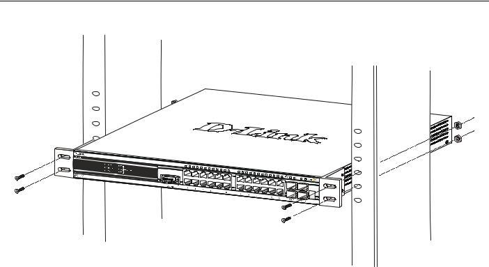
xStack DGS-3400 Series Layer 2 Gigabit Ethernet Managed Switch
Mounting the Switch in a Standard 19" Rack
Figure 2- 18. Installing Switch in a rack
Power On
1.Plug one end of the AC power cord into the power connector of the Switch and the other end into the local power source outlet.
2.After powering on the Switch, the LED indicators will momentarily blink. This blinking of the LED indicators represents a reset of the system.
Power Failure
As a precaution, in the event of a power failure, unplug the Switch. When power is resumed, plug the Switch back in.
11

xStack DGS-3400 Series Layer 2 Gigabit Ethernet Managed Switch
Installing the SFP ports
The xStack DGS-3400 series switches are equipped with SFP (Small Form Factor Portable) ports, which are to be used with fiberoptical transceiver cabling in order to uplink various other networking devices for a gigabit link that may span great distances. These SFP ports support full-duplex transmissions, have auto-negotiation and can be used with DEM-310GT (1000BASE-LX), DEM-311GT (1000BASE-SX), DEM-314GT (1000BASE-LH) and DEM-315GT (1000BASE-ZX) transceivers. See the figure below for installing the SFP ports in the Switch.
Figure 2- 19. Inserting the fiber-optic transceivers into the DGS-3426
12
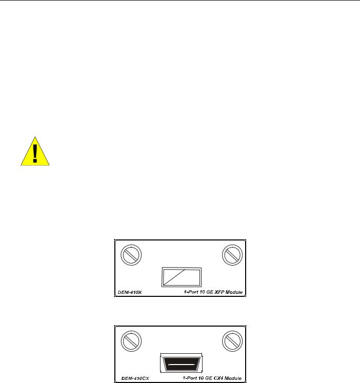
xStack DGS-3400 Series Layer 2 Gigabit Ethernet Managed Switch
The Optional Module
The rear panel of the DGS-3426, DGS-3426P, DGS-3427 and DGS-3450 include open slots that may be equipped with the DEM410X 1-port 10GE XFP stacking uplink module, or a DEM-410CX 1-port 10GBASE-CX4 stacking uplink module, both sold separately. These modules may be used to stack switches in a switch stack using a Duplex Ring or Duplex Chain topology.
Adding the DEM-410X optional module will allow the administrator to transmit data at a rate of ten gigabits a second. The module port(s) are compliant with standard IEEE 802.3ae, support full-duplex transmissions only and must be used with XFP MSA compliant transceivers.
The DEM-410CX uses copper wire medium, not optic fiber and therefore has a transmit length limit up to 1 meter. Compliant with the IEEE802.3ak standard, this module uses a 4-laned copper connector for data transfer in full-duplex mode within a stacking configuration.
To install these modules in the DGS-3400 Series Switch, follow the simple steps listed below.
CAUTION: Before adding the optional module, make sure to disconnect all power sources connected to the Switch. Failure to do so may result in an electrical shock, which may cause damage, not only to the individual but to the Switch as well.
At the back of the Switch to the left is the slot for the optional module. This slot must be covered with the faceplate if the slot is not being used. If a module will be installed in an available slot, the faceplate is easily removed by loosening the screws and pulling off the plate.
The front panels of the available modules are shown here:
Figure 2- 20. Front Panel of the DEM-410X
Figure 2- 21. Front Panel of the DEM-410CX
13

xStack DGS-3400 Series Layer 2 Gigabit Ethernet Managed Switch
Installing the Module
Unplug the Switch before removing the faceplate covering the empty slot. To install the module, slide it in to the available slot at the rear of the Switch until it reaches the back, as shown in the following figure. Gently, but firmly push in on the module to secure it to the Switch. The module should fit snugly into the corresponding receptors.
Figure 2- 22. Inserting the optional module into the Switch (DGS-3450)
Now tighten the two screws at adjacent ends of the module into the available screw holes on the Switch. The upgraded Switch is now ready for use.
Figure 2- 23. DGS-3450 with optional DEM-410X module installed
14
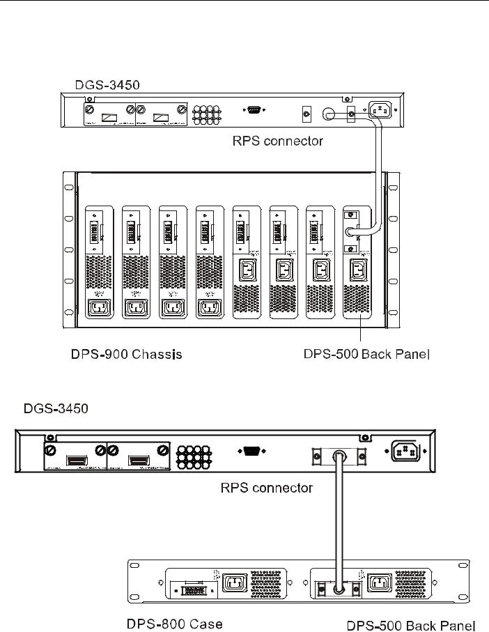
xStack DGS-3400 Series Layer 2 Gigabit Ethernet Managed Switch
External Redundant Power System
The Switch supports an external redundant power system. The diagrams below illustrate a proper RPS power connection to the Switch. Please consult the documentation for information on power cabling and connectors and setup procedure.
Figure 2- 24. The DGS-3450 with the DPS-500 chassis RPS
Figure 2- 25. The DGS-3450 with the DPS-500 Redundant External Power Supply
15
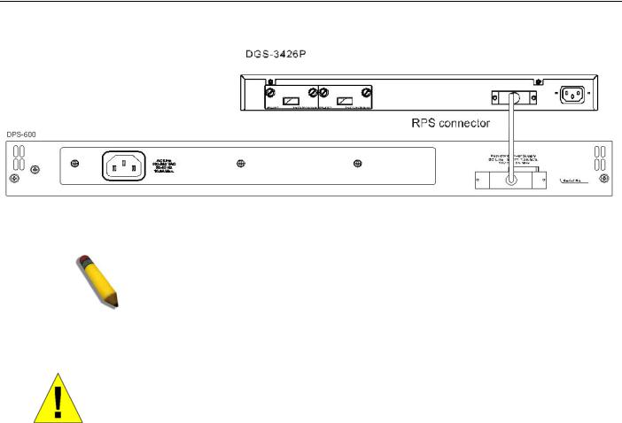
xStack DGS-3400 Series Layer 2 Gigabit Ethernet Managed Switch
Alternate to the other Switches in the xStack DGS-3400 Switch Series, the DGS-3426P utilizes the DPS-600 as its External Redundant Power Supply. The DPS-600 is the ONLY RPS to be used with the DGS-3426P.
NOTE: See the DPS-500 or DPS-600 documentation for more information.
CAUTION: Do not use the Switch (except DGS-3426P) with any redundant power system other than the DPS-500.
16
Loading...