


DES-3028
Table of contents
 Loading...
User Manual
Product Model : DES-3028/DES-3028P/DES-3028G/DES-
3052/DES-3052P
Managed 10/100Mbps Fast Ethernet Switch
Release 2
©Copyright 2009. All rights reserved.

________________________________________________________________________________________________________
Information in this document is subject to change without notice.
© 2009 D-Link Corporation. All rights reserved.
Reproduction in any manner whatsoever without the written permission of D-Link Computer Corporation is strictly forbidden.
Trademarks used in this text: D-Link and the D-LINK logo are trademarks of D-Link Computer Corporation; Microsoft and Windows are registered trademarks of
Microsoft Corporation.
Other trademarks and trade names may be used in this document to refer to either the entities claiming the marks and names or their products. D-Link Computer
Corporation disclaims any proprietary interest in trademarks and trade names other than its own.
January 2009 P/N 651ES3028025G
©Copyright 2009. All rights reserved.

DES-3028 DES-3028P DES-3028G DES-3052 DES-3052P Layer 2 Fast Ethernet Managed Switch
Table of Contents
Preface........................................................................................................................................................... viii
Intended Readers ............................................................................................................................................ix
Typographical Conventions ...........................................................................................................................ix
Notes, Notices, and Cautions..........................................................................................................................ix
Safety Instructions ...........................................................................................................................................x
Safety Cautions..............................................................................................................................................................................x
General Precautions for Rack-Mountable Products......................................................................................................................xi
Protecting Against Electrostatic Discharge..................................................................................................................................xii
Introduction...................................................................................................................................................... 1
DES-3028/28P/28G/52/52P.............................................................................................................................. 1
Features.......................................................................................................................................................................................... 1
Ports...............................................................................................................................................................................................2
LED Indicators............................................................................................................................................................................... 3
Front-Panel Description.................................................................................................................................................................5
Rear Panel Description................................................................................................................................................................... 6
Side Panel Description................................................................................................................................................................... 6
Gigabit Combo Ports......................................................................................................................................................................7
Installing the SFP ports.................................................................................................................................................................. 8
Installation........................................................................................................................................................ 9
Package Contents........................................................................................................................................................................... 9
Before You Connect to the Network.............................................................................................................................................. 9
Installing the Switch without the Rack ........................................................................................................................................ 10
Installing the Switch in a Rack..................................................................................................................................................... 10
Mounting the Switch in a Standard 19" Rack..............................................................................................................................11
Connecting the Switch ...................................................................................................................................12
Switch to End Node..................................................................................................................................................................... 12
Switch to Hub or Switch.............................................................................................................................................................. 13
Introduction to Switch Management ...........................................................................................................14
Management Options.....................................................................................................................................14
Web-based Management Interface............................................................................................................................................... 14
SNMP-Based Management.......................................................................................................................................................... 14
Connecting the Console Port (RS-232 DCE)............................................................................................................................... 14
First Time Connecting to the Switch ........................................................................................................................................... 16
Password Protection..................................................................................................................................................................... 16
SNMP Settings............................................................................................................................................................................. 17
IP Address Assignment................................................................................................................................................................ 18
Web-based Switch Configuration.................................................................................................................21
Introduction....................................................................................................................................................
ii
21

DES-3028 DES-3028P DES-3028G DES-3052 DES-3052P Layer 2 Fast Ethernet Managed Switch
Login to Web Manager................................................................................................................................................................21
Web-based User Interface............................................................................................................................................................ 22
Web Pages.................................................................................................................................................................................... 24
Administration ...............................................................................................................................................25
Device Information ........................................................................................................................................26
IP Address.......................................................................................................................................................28
Setting the Swith’s IP Address using the Console Interface ........................................................................................................ 30
Port Configuration......................................................................................................................................... 31
Port Settings................................................................................................................................................................................. 31
Port Description...........................................................................................................................................................................33
Port Error Disabled......................................................................................................................................................................33
DHCP/BOOTP Relay ....................................................................................................................................35
DHCP/BOOTP Relay Global Settings......................................................................................................................................... 35
DHCP/BOOTP Relay Interface Settings......................................................................................................................................38
DHCP Local Relay Settings......................................................................................................................................................... 38
User Accounts................................................................................................................................................. 40
Cable Diagnostics........................................................................................................................................... 42
Port Mirroring ...............................................................................................................................................44
System Log Settings .......................................................................................................................................45
Log Settings ....................................................................................................................................................47
SNTP Settings.................................................................................................................................................48
Time Settings...............................................................................................................................................................................48
Time Zone and DST..................................................................................................................................................................... 49
MAC Notification Settings ............................................................................................................................51
TFTP Services ................................................................................................................................................
Multiple Image Services ................................................................................................................................5
Firmware Information..................................................................................................................................................................53
Config Firmware Image............................................................................................................................................................... 53
52
3
Ping Test .........................................................................................................................................................54
Safeguard Engine........................................................................................................................................... 54
SNMP Manager..............................................................................................................................................57
SNMP Settings............................................................................................................................................................................. 57
SNMP Traps Settings................................................................................................................................................................... 58
SNMP User Table........................................................................................................................................................................ 58
SNMP View Table....................................................................................................................................................................... 60
SNMP Group Table ..................................................................................................................................................................... 61
SNMP Community Table Configuration ..................................................................................................................................... 62
SNMP Host Table........................................................................................................................................................................ 63
SNMP Engine ID......................................................................................................................................................................... 64
PoE System .....................................................................................................................................................65
iii

DES-3028 DES-3028P DES-3028G DES-3052 DES-3052P Layer 2 Fast Ethernet Managed Switch
PoE System Configuration........................................................................................................................................................... 65
PoE Port Configuration................................................................................................................................................................ 66
Single IP Settings............................................................................................................................................68
SIM Settings................................................................................................................................................................................. 69
Topology...................................................................................................................................................................................... 71
Tool Tips ...................................................................................................................................................................................... 73
Right-Click................................................................................................................................................................................... 74
Menu Bar ..................................................................................................................................................................................... 76
Firmware Upgrade.......................................................................................................................................................................77
Configuration Backup/Restore..................................................................................................................................................... 77
Upload Log..................................................................................................................................................................................78
Forwarding & Filtering.................................................................................................................................78
Unicast Forwarding...................................................................................................................................................................... 78
Multicast Forwarding................................................................................................................................................................... 79
Multicast Filtering Mode ............................................................................................................................................................. 81
SMTP Service................................................................................................................................................. 82
SMTP Server Settings.................................................................................................................................................................. 83
SMTP Service.............................................................................................................................................................................. 83
L2 Features..................................................................................................................................................... 85
VLANs.............................................................................................................................................................85
Static VLAN Entry....................................................................................................................................................................... 90
GVRP Settings............................................................................................................................................................................. 92
VLAN Trunk Settings.................................................................................................................................................................. 94
QinQ............................................................................................................................................................................................. 96
Trunking .........................................................................................................................................................98
Link Aggregation......................................................................................................................................................................... 99
LACP Port Settings...................................................................................................................................................................... 99
IGMP Snooping............................................................................................................................................101
Router Ports Settings.................................................................................................................................................................. 103
IGMP Authentication................................................................................................................................................................. 105
Dynamic IP Multicast Learning................................................................................................................................................. 107
ISM VLAN Settings................................................................................................................................................................... 108
IP Multicast Filter Profile Settings............................................................................................................................................. 110
Limited Multicast Range Settings.............................................................................................................................................. 111
Max Multicast Group Settings................................................................................................................................................... 113
MLD Snooping .............................................................................................................................................114
MLD Snooping Settings............................................................................................................................................................. 114
MLD Snooping Router Port Settings......................................................................................................................................... 116
Spanning Tree ..............................................................................................................................................117
STP Bridge Global Settings....................................................................................................................................................... 120
STP Port Settings....................................................................................................................................................................... 123
iv

DES-3028 DES-3028P DES-3028G DES-3052 DES-3052P Layer 2 Fast Ethernet Managed Switch
MST Configuration Identification.............................................................................................................................................. 125
STP Instance Settings................................................................................................................................................................. 127
MSTP Port Information ............................................................................................................................................................. 128
Loopback Detection Settings.......................................................................................................................130
LLDP.............................................................................................................................................................131
LLDP Global Settings................................................................................................................................................................ 131
Basic LLDP Port Settings .......................................................................................................................................................... 133
802.1 Extension LLDP Port Settings.........................................................................................................................................134
802.3 Extension LLDP Port Settings.........................................................................................................................................136
LLDP Management Address Settings........................................................................................................................................ 138
LLDP Statistics..........................................................................................................................................................................139
LLDP Management Address Table............................................................................................................................................ 140
LLDP Local Port Table.............................................................................................................................................................. 140
LLDP Remote Port Table .......................................................................................................................................................... 142
CoS ................................................................................................................................................................143
Port Bandwidth ............................................................................................................................................146
802.1p Default Priority ................................................................................................................................147
802.1p User Priority..................................................................................................................................... 149
CoS Scheduling Mechanism........................................................................................................................ 149
CoS Output Scheduling ...............................................................................................................................150
Priority Settings ...........................................................................................................................................151
TOS Priority Settings ..................................................................................................................................153
DSCP Priority Settings ................................................................................................................................154
Port Mapping Priority Settings ..................................................................................................................155
MAC Priority ...............................................................................................................................................
ACL ...............................................................................................................................................................
156
157
Time Range...................................................................................................................................................157
Access Profile Table.....................................................................................................................................157
CPU Interface Filtering...............................................................................................................................169
CPU Interface Filtering State..................................................................................................................................................... 169
CPU Interface Filtering Profile Table........................................................................................................................................ 169
Security .........................................................................................................................................................181
Traffic Control .............................................................................................................................................181
Port Security................................................................................................................................................. 185
Port Lock Entries.........................................................................................................................................186
IP-MAC-Port Binding .................................................................................................................................187
IMP Global Settings................................................................................................................................................................... 187
IMP Port Settings....................................................................................................................................................................... 187
IMP Entry Settings..................................................................................................................................................................... 189
v

DES-3028 DES-3028P DES-3028G DES-3052 DES-3052P Layer 2 Fast Ethernet Managed Switch
DHCP Snooping Entries ............................................................................................................................................................ 190
MAC Block List......................................................................................................................................................................... 190
SSL ................................................................................................................................................................191
Download Certificate.................................................................................................................................................................191
Ciphersuite................................................................................................................................................................................. 191
SSH................................................................................................................................................................ 194
SSH Server Configuration ......................................................................................................................................................... 194
SSH Authentication Mode and Algorithm Settings ................................................................................................................... 195
SSH User Authentication...........................................................................................................................................................197
802.1X............................................................................................................................................................198
802.1X Authenticator Settings...................................................................................................................................................205
Local Users ................................................................................................................................................................................ 208
802.1X Capability Settings ........................................................................................................................................................ 209
Configure 802.1X Guest VLAN ................................................................................................................................................ 209
Initializing Ports for Port Based 802.1X....................................................................................................................................210
Initializing Ports for Host Based 802.1X................................................................................................................................... 211
Reauthenticate Port(s) for Port Based 802.1X ........................................................................................................................... 212
Reauthenticate Port(s) for Host-based 802.1X........................................................................................................................... 213
RADIUS Server ......................................................................................................................................................................... 213
Trusted Host................................................................................................................................................. 214
Access Authentication Control ...................................................................................................................215
Authentication Policy and Parameter Settings...........................................................................................................................216
Application Authentication Settings .......................................................................................................................................... 216
Authentication Server Group ..................................................................................................................................................... 217
Authentication Server Host........................................................................................................................................................ 218
Login Method Lists.................................................................................................................................................................... 221
Enable Method Lists .................................................................................................................................................................. 222
Configure Local Enable Password.............................................................................................................................................225
Enable Admin ............................................................................................................................................................................ 225
Traffic Segmentation ...................................................................................................................................226
DoS Attack Prevention ................................................................................................................................227
Monitoring.................................................................................................................................................... 232
CPU Utilization ............................................................................................................................................232
Port Utilization............................................................................................................................................. 233
Packets ..........................................................................................................................................................234
Received (RX) ........................................................................................................................................................................... 235
UMB Cast (RX).........................................................................................................................................................................237
Transmitted (TX)....................................................................................................................................................................... 239
Packet Errors ...............................................................................................................................................241
Received (RX) ........................................................................................................................................................................... 241
vi

DES-3028 DES-3028P DES-3028G DES-3052 DES-3052P Layer 2 Fast Ethernet Managed Switch
Transmitted (TX)....................................................................................................................................................................... 243
Packet Size ....................................................................................................................................................245
MAC Address ...............................................................................................................................................247
Switch Log ....................................................................................................................................................249
IGMP Snooping Group ...............................................................................................................................250
Browse Router Port .....................................................................................................................................251
VLAN Status.................................................................................................................................................251
MLD Snooping Group.................................................................................................................................251
Browse MLD Snooping Router Port.......................................................................................................... 252
Static ARP Settings...................................................................................................................................... 253
ARP-FDB......................................................................................................................................................
253
Gratuitous ARP Settings .............................................................................................................................255
Session Table ................................................................................................................................................
256
Port Access Control .....................................................................................................................................256
RADIUS Authentication............................................................................................................................................................ 256
RADIUS Accounting.................................................................................................................................................................258
Reset ..............................................................................................................................................................259
Reboot System ..............................................................................................................................................260
Save Changes................................................................................................................................................260
Logout ...........................................................................................................................................................261
Technical Specifications ..............................................................................................................................262
System Log Entries ......................................................................................................................................268
Standard Trap List...................................................................................................................................................................... 278
Proprietary Trap List.................................................................................................................................................................. 279
Proprietary Trap List (project dependent).................................................................................................................................. 279
Cable Lengths............................................................................................................................................... 281
Password Recovery Procedure ...................................................................................................................282
Glossary ........................................................................................................................................................
284
ARP Packet Content ACL...........................................................................................................................286
Warranties/Registration.............................................................................................................................. 296
Tech Support ................................................................................................................................................305
vi
i

DES-3028 DES-3028P DES-3028G DES-3052 DES-3052P Layer 2 Fast Ethernet Managed Switch
Preface
The DES-3028/DES-3028P/DES-3028G/DES-3052/DES-3052P User Manual is divided into sections that describe the system
installation and operating instructions with examples.
Section 1, Introduction - Describes the Switch and its features.
Section 2, Installation - Helps you get started with the basic installation of the Switch and also describes the front panel, rear
panel, side panels, and LED indicators of the Switch.
Section 3, Connecting the Switch - Tells how you can connect the Switch to your Ethernet/Fast Ethernet network.
Section 4, Introduction to Switch Management - Introduces basic Switch management features, including password protection,
SNMP settings, IP address assignment and connecting devices to the Switch.
Section 5, Introduction to Web-based Switch Management - Talks about connecting to and using the Web-based switch
management feature on the Switch.
Section 6, Administration - A detailed discussion about configuring the basic functions of the Switch, including Device
Information, IP Address, Port Configuration, DHCP/BOOTP Relay, User Accounts, Cable Diagnostics, Port Mirroring, System
Log Settings, Log Settings, SNTP Settings, MAC Notification Settings, TFTP Services, Multiple Image Services, Ping Test,
Safeguard Engine, SNMP Manager, Single IP Settings, Forwarding & Filtering, and SMTP Service.
Section 7, Layer 2 Features - A discussion of Layer 2 features of the Switch, including VLAN, QinQ, Trunking, IGMP
Snooping, MLD Snooping, Spanning Tree, Loopback Detection and LLDP.
Section 8, CoS - Features information on CoS, including Port Bandwidth, 802.1P Default Priority, 802.1P User Priority, CoS
Scheduling Mechanism, CoS Output Scheduling, Priority Settings, TOS Priority Settings, DSCP Priority Settings, Port Mapping
Priority Settings, and MAC Priority.
Section 9, ACL - Discussion on the ACL function of the Switch, including Time Range, Access Profile Table and CPU Interface
Filtering.
Section 10, Security - A discussion on the Security functions on the Switch, including Traffic Control, Port Security, Port Lock
Entries, IP-MAC-Port Binging, SSL, SSH, 802.1X, Trusted Host, Access Authentication Control, Traffic Segmentation and DoS
Attack Prevention.
Section 11, Monitoring - Features information on Monitoring including CPU Utilization, Port Utilization, Packets, Packet Errors,
Packet Size, MAC Address, Switch Log, IGMP Snooping Group, Browse Router Port, VLAN Status, MLD Snooping Group,
Browse MLD Snooping Router Port, Static ARP Settings, ARP-FDB, Gratuitous ARP Settings, Session Table, and Port Access
Control.
Appendix A, Technical Specifications - Technical specifications for the DES-3028/DES-3028P/DES-3 028G/DES-3052 and the
DES-3052P.
Appendix B, System Log Entries - Information on the System Log Entries
Appendix C, Cable Lengths - Information on cable types and maximum distances.
Appendix D, Glossary - Lists definitions for terms and acronyms used in this document.
viii

DES-3028 DES-3028P DES-3028G DES-3052 DES-3052P Layer 2 Fast Ethernet Managed Switch
Intended Readers
The DES-3028/DES-3028P/DES-3028G/DES-3052 /DES-3052P User Manual contains information for setup and management of
the Switch. The term, “the Switch” will be used when referring to all five switches. This manual is intended for network managers
familiar with network management concepts and terminology.
Typographical Conventions
Convention Description
[ ]
Bold font
Boldface
Typewriter Font
Initial capital letter
Italics
Menu Name > Menu
Option
In a command line, square brackets indicate an optional entry. For example: [copy filename]
means that optionally you can type copy followed by the name of the file. Do not type the
brackets.
Indicates a button, a toolbar icon, menu, or menu item. For example: Open the File menu
and choose Cancel. Used for emphasis. May also indicate system messages or prompts
appearing on your screen. For example: You have mail. Bold font is also used to represent
filenames, program names and commands. For example: use the copy command.
Indicates commands and responses to prompts that must be typed exactly as printed in the
manual.
Indicates a window name. Names of keys on the keyboard have initial capitals. For example:
Click Enter.
Indicates a window name or a field. Also can indicate a variables or parameter that is
replaced with an appropriate word or string. For example: type filename means that you
should type the actual filename instead of the word shown in italic.
Menu Name > Menu Option Indicates the menu structure. Device > Port > Port
Properties means the Port Properties menu option under the Port menu option that is
located under the Device menu.
Notes, Notices, and Cautions
A NOTE indicates important information that helps you make better use of your device.
A NOTICE indicates either potential damage to hardware or loss of data and tells you
how to avoid the problem.
A CAUTION indicates a potential for property damage, personal injury, or death.
ix

DES-3028 DES-3028P DES-3028G DES-3052 DES-3052P Layer 2 Fast Ethernet Managed Switch
Safety Instructions
Use the following safety guidelines to ensure your own personal safety and to help protect your system from potential damage.
Throughout this document, the caution icon ( ) is used to indicate cautions and precautions that you need to review and
follow.
Safety Cautions
To reduce the risk of bodily injury, electrical shock, fire, or damage to the equipment, observe the following precautions.
Observe and follow service markings.
Do not service any product except as explained in your system documentation.
Opening or removing covers that are marked with the tr iangular symbol with a lightning bolt may expose you to
electrical shock.
Only a trained service technician should service components inside these compartments.
If any of the following conditions occur, unplug the product from the electrical outlet and replace the part or contact your
trained service provider:
The power cable, extension cable, or plug is damaged.
An object has fallen into the product.
The product has been exposed to water.
The product has been dropped or damaged.
The product does not operate correctly when you follow the operating instructions.
Keep your system away from radiators and heat sources. Also, do not block cooling vents.
Do not spill food or liquids on your system components, and never operate the product in a wet environment. If the system
gets wet, see the appropriate section in your troubleshooting guide or contact yo ur trained service provider.
Do not push any objects into the openings of your system. Do ing so can cause fire or electric shock by shorting out interior
components.
Use the product only with approved equipment.
Allow the product to cool before removing covers or touching internal components.
Operate the product only from the type of external power source indicated on the electrical ratings label. If you are not sure
of the type of power source required, consult your service provider or local power company.
To help avoid damaging your system, be sure the voltage on the power supply is set to match the power available at your
location:
115 volts (V)/60 hertz (Hz) in most of North and South America and some Far Eastern countries such as South
Korea and Taiwan
100 V/50 Hz in eastern Japan and 100 V/60 Hz in western Japa n
230 V/50 Hz in most of Europe, the Middle East, and the Far East
Also, be sure that attached devices are electrically rated to operate with the power available in your location.
Use only approved power cable(s). If you have not been provided with a power cable for your system or for any AC-
powered option intended for your system, purchase a power cable th at is approved for us e in your country. The power cable
must be rated for the product and for the voltage and current marked on the product's electrical ratings label. The voltage and
current rating of the cable should be greater than the ratings marked on the product.
To help prevent electric shock, plug the system and peripheral power cables into properly grounded electrical outlets. These
cables are equipped with three-prong plugs to help ensure proper grounding. Do not use adapter plugs or remove the
grounding prong from a cable. If you must use an extension cable, use a 3-wir e cable with prop erly grounded plugs.
Observe extension cable and power strip ratings. Make su re that the total ampere rating of all products plugged into the
extension cable or power strip does not exceed 80 percent of the ampere ratings limit for the extension cable or power strip.
x

DES-3028 DES-3028P DES-3028G DES-3052 DES-3052P Layer 2 Fast Ethernet Managed Switch
To
help protect your system from sudden, transient increases and decreases in electrical power, use a surge suppressor, line
conditioner, or uninterruptible power supply (UPS).
Position system cables and power cables carefully; route cables so that they cannot be stepped on or tripped over. Be sure
that nothing rests on any cables.
Do not modify power cables or plugs. Consult a licensed electrician or your power company for site modifications. Always
follow your local/national wiring rules.
When connecting or disconnecting power to hot-pluggable power supplies, if offered with your system, observe the
following guidelines:
Install the power supply before connecting the power cable to the power supply.
Unplug the power cable before removing the power supply.
If the system has multiple sources of power, disconnect power from the system by unplugging all power cables from
the power supplies.
Move products with care; ensure that all casters and/or stabilizers are firmly connected to the system. Avoid sudden stops
and uneven surfaces.
General Precautions for Rack-Mountable Products
Observe the following precautions for rack stability an d safety. Also, refer to the rack installation documentation accompanyin g
the system and the rack for specific caution statements and procedures.
Systems are considered to be components in a rack. Thus, "component" refers to any system as well as to various peripherals
or supporting hardware.
Before working on the rack, make sure that the stabilizers are secured to the rack, extended to the floor, and that the full
weight of the rack rests on the floor. Install front and side stabilizers on a single rack or front stabilizers for joined multiple
racks before working on the rack.
Always load the rack from the bottom up, and load the heaviest item in the rack first.
Make sure that the rack is level and stable before extending a component from the rack.
Use caution when pressing the component rail release latches and sliding a component into or out of a rack; the slide rails
can pinch your fingers.
After a component is inserted into the rack, carefully extend the rail into a locking position, and then slide the component
into the rack.
Do not overload the AC supply branch circuit that provides power to the rack. The total rack load should not exceed 80
percent of the branch circuit rating.
Ensure that proper airflow is provided to components in the rack.
Do not step on or stand on any component when servicing other components in a rack.
NOTE: A qualified electrician must perform all connections to DC power and to safety
grounds. All electrical wiring must comply with applicable local, regional or national codes
and practices.
CAUTION: Never defeat the ground conductor or operate the equipment in the absence of a
suitably installed ground conductor. Contact the appropriate electrical inspection authority or
an electrician if you are uncertain that suitable grounding is available.
xi

DES-3028 DES-3028P DES-3028G DES-3052 DES-3052P Layer 2 Fast Ethernet Managed Switch
CAUTION: The system chassis must be positively grounded to the rack cabinet frame. Do
not attempt to connect power to the system until grounding cables are connected. A
qualified electrical inspector must inspect completed power and safety ground wiring. An
energy hazard will exist if the safety ground cable is omitted or disconnected.
CAUTION: Do not replace the battery with an incorrect type. The risk of explosion exists if
the replacement battery is not the correct lithium battery type. Dispose of used batteries
according to the instructions.
Protecting Against Electrostatic Discharge
Static electricity can harm delicate components inside your system. To prevent static damage, discharge static electricity from
your body before you touch any of the electronic components, such as the microprocessor. You can do so by periodically touching
an unpainted metal surface on the chassis.
You can also take the following steps to prevent damage from electrostatic discharge (ESD):
1. When unpacking a static-sensitive component from its shipping carton, do not remove the component from the antistatic
packing material until you are ready to install the component in your system. Just before unwrapping the antistatic
packaging, be sure to discharge static electricity from your body.
2. When transporting a sensitive component, first place it in an antistatic container or packaging.
3. Handle all sensitive components in a static-safe area. If possible, use antistatic floor pads, workbench pads and an
antistatic grounding strap.
xii

DES-3028 DES-3028P DES-3052 DES-3052P Layer 2 Fast Ethernet Managed Switch
Section 1
Introduction
DES-3028/28P/28G/52/52P Switch Description
Features
Ports
LED Indicators
Front-Panel Description
Rear Panel Description
Side Panel Description
Installing SFP ports
DES-3028/28P/28G/52/52P
The DES-3028, DES-3028P, DES-3028G, DES-3052, and the DES-3052P ar e all members of the D-Link Switch family. These
Switches provide unsurpassed performance, fault tolerance, scalable flexibility, robust security, standard-based interoperability
and impressive technology to future-proof departmental and enterprise network deployments with an easy migration path.
The following manual describes the installation, maintenance, and configurations concerning the DES-3028, DES-3028P, DES3028G, DES-3052, and DES-3052P. These five Switches are identical in configuration and very similar in basic hardware and
consequentially, most of the information in this manual will be universal to the total group of switches. Corresponding screen
pictures of the web manager may be taken from any one of these switches but the configuration will be identical, except for
varying port counts. For the remainder of this document, we will use the DES-3028G as the Switch in question for examples,
screen shots, configurations, and explanations.
Features
IEEE 802.3ad Link Aggregation Control Protocol support
IEEE 802.1X Port-based and Host-based Access Control
IEEE 802.1Q VLAN
IEEE 802.1D Spanning Tree, IEEE 802.1w Rapid Spanning Tree and IEEE 802.1s Multiple Spanning Tree support
Access Control List (ACL) support
Single IP Management support
Access Authentication Control utilizing TACACS, XTACACS and TACACS+
Internal Flash Drive for saving configurations and firmware
Simple Network Time Protocol support
MAC Notification support
System and Port Utilization support
System Log Support
Support port-based enable and disable
Address table: Supports up to 8K MAC addresses per device
Supports a packet buffer of up to 512K bytes
Supports Port-based VLAN Groups
Port Trunking with flexible load dist ri b uti o n and fail-over function
IGMP Snooping support
SNMP support
Secure Sockets Layer (SSL) and Secure Shell (SSH) support
Port Mirroring support
MIB support for:
RFC1213 MIB II
1

DES-3028 DES-3028P DES-3052 DES-3052P Layer 2 Fast Ethernet Managed Switch
RFC1493 Bridge
RFC2819 RMON
RFC2665 Ether-like MIB
RFC2863 Interface MIB
Private MIB
RFC2674 for 802.1p
IEEE 802.1X MIB
IEEE 802.3x flow control in full duplex mode
IEEE 802.1p Priority Queues
IEEE 802.3u 100BASE-TX compliant
RS-232 DCE console port for Switch ma nagement
Provides parallel LED display for port status such as link/act, speed, etc.
IEEE 802.3 10BASE-T compliant
High performance switching engine performs forwarding and filtering at wire speed, maximum 14,881 packets/sec
on each 10Mbps Ethernet port, maximum 148,810 packet/sec on 100Mbps Fast Ethernet port and 1,488,100 for each
Gigabit port
Full and half-duplex for both 10Mbps and 100Mbps connections. Full duplex allows the switch port to
simultaneously transmit and receive data. It only works with connections to full-duplex-capable end stations and
switches. Connections to a hub must take place at half-duplex
Support Broadcast/Multicast storm control
Non-blocking store and forward switching scheme capability to support rate adaptation and protocol conversion
Supports by-port Egress/Ingress rate control
Efficient self-learning and address recognition mechanism enables forwarding rate at wire speed
2

DES-3028 DES-3028P DES-3028G DES-3052 DES-3052P Layer 2 Fast Ethernet Managed Switch
Ports
The following table lists the relative ports that are present within each switch:
DES-3028 and DES-3028P DES-3028G DES-3052 and DES-3052P
Twenty-four 10/100BASE-T
Two 1000Base-T/SFP Combo
Ports
Two 1000Base-T Ports
One female DCE RS-232 DB-9
console port
The following table lists the features and compatibility for each type of port present in the DES-3028/28P/28G/52/52P.
10/100/1000BASE-T SFP Combo 1000BASE-T Combo
IEEE 802.3 compliant
IEEE 802.3u compliant
IEEE 802.3x flow control
support in full-duplex
Auto MDI-X/MDI-II cross
over supported except
for speed 1000M force
mode.
Twenty-four 10/100BASE-T
Four 1000Base-T/SFP Combo
Ports
One female DCE RS-232 DB-9
console port
SFP Transceivers Supported:
DEM-310GT (1000BASE-LX)
DEM-311GT (1000BASE-SX)
DEM-314GT (1000BASE-LH)
DEM-315GT (1000BASE-ZX)
DEM-210 (Single Mode
100BASE-FX)
DEM-211 (Multi Mode
100BASE-FX)
WDM Transceiver Supported:
DEM-330T (TX-1550/RX1310nm), up to 10km,SingleMode
DEM-330R (TX-1310/RX1550nm), up to 10km,SingleMode
DEM-331T (TX-1550/RX1310nm), up to 40km, SingleMode
DEM-331R (TX-1310/RX1550nm), up to 40km, SingleMode
Compliant to the following
standards:
1. IEEE 802.3z compliance
Forty-eight 10/100Mbps Ports
Two 1000Base-T/SFP Combo Ports
Two 1000Base-T Ports
One female DCE RS-232 DB-9
console port
IEEE 802.3 compliant
IEEE 802.3u compliant
IEEE 802.3ab compliant
IEEE 802.3z compliant
IEEE 802.3x flow control
support in full-duplex
2.IEEE 802.3u compliance
NOTE: The SFP combo ports on the Switch cannot be used simultaneously with the
corresponding 1000BASE-T ports. If both ports are in use at the same time (ex. port 25
of the SFP and port 25 of the 1000BASE-T), the SFP ports will take priority over the
combo ports and render the 1000BASE-T ports inoperable.
2
DES-3028 DES-3028P DES-3028G DES-3052 DES-3052P Layer 2 Fast Ethernet Managed Switch
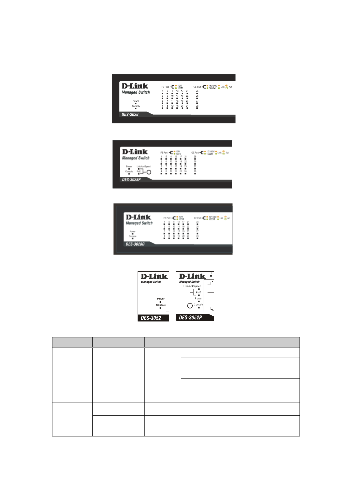
LED Indicators
The Switch supports LED indicators for Power, Console, RPS and Port LEDs. The following shows the LED indicators for the
DES-3028/28P/28G/52/52P Series switches along with an explanation of each indicator. LEDs and there corresponding meanings
are displayed below.
Figure 1- 1. LED Indicators on DES-3028 Switch
Figure 1- 2. LED Indicators on DES-3028P Switch
Figure 1- 3. LED Indicators on DES-3028G Switch
Figure 1- 4. LED Indicators on DES-3052/DES-3052P Switch
Location LED Indicative Color Status Description
Solid Light Power On
Light off Power Off
Solid Light Console on
Blinking
Light off Console off
POST is in progress/ POST
is failure.
Per Device
“Mode Select
Button”(only
for DES3028P/DES3052P)
Power
Console
Link/Act/ Speed
PoE
Green
Green
Green Solid Light Link/Act/Speed Mode
Green Solid Light PoE Mode
3

DES-3028 DES-3028P DES-3028G DES-3052 DES-3052P Layer 2 Fast Ethernet Managed Switch
A
A
A
A
W
hen there is a secure
Solid Green
100Mbps Fast Ethernet
connection (or link) at any of
the ports.
When there is reception or
transmission (i.e. Activity—
Blinking Green
ct) of data occurring at a
Fast Ethernet connected
Link/Act/Speed
Green/Amber
port.
When there is a secure
Solid Amber
10Mbps Ethernet connection
(or link) at any of the ports.
LED Per
10/100 Mbps
Port
Blinking Amber
When there is reception or
transmission (i.e. Activity—
Act) of data occurring at an
Ethernet connected port.
Light off No link
LED Per GE
Port
PoE (only for
DES-3028P/DES3052P)
Link/Act/Speed
mode for
1000BASE-T ports
Link/Act/Speed
mode for SFP
ports
Green
Green/Amber
Green/Amber
Solid Green
Blinking
Powered device is
connected.
Port has detected a error
condition
Powered Device may receive
Light off
power from an AC power
source or no 802.3af PD is
found
When there is a secure
Solid Green
1000Mbps connection (or
link) at any of the ports.
When there is reception or
Blinking Green
transmission (i.e. Activity--
ct) of data occurring at a
1000Mbps connected port.
When there is a secure
Solid Amber
10/100Mbps Fast Ethernet
connection (or link) at any of
the ports.
When there is reception or
transmission (i.e. Activity—
Blinking Amber
ct) of data occurring at a
Fast Ethernet connected
port.
Light off No link
When there is a secure
Solid Green
1000Mbps connection (or
link) at the ports.
When there is reception or
Blinking Green
transmission (i.e. Activity--
ct) of data occurring at a
1000Mbps connected port.
When there is a secure
Solid Amber
100Mbps connection (or link)
at any of the ports.
When there is reception or
Blinking Amber
transmission (i.e. Activity—
Act) of data occurring at the
ports.
Light off No link
4
DES-3028 DES-3028P DES-3028G DES-3052 DES-3052P Layer 2 Fast Ethernet Managed Switch
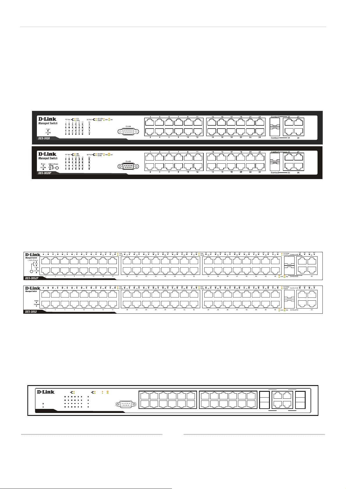
Front-Panel Description
DES-3028/DES-3028P
Twenty-four 10/100Mbps BASE-T ports
Two Combo 1000BASE-T/SFP ports located to the right
Two 1000BASE-T ports located to the right
One female DCE RS-232 DB-9 console port
LEDs for Power, Console, PoE, Link/Act/Speed for each port
Figure 1- 5. Front Panel of the DES-3028/DES-3028P
DES-3052P/DES-3052
rty-eight 10/100Mbps BASE-T ports
Fo
Two Combo 1000BASE-T/SFP ports located to the right
Two 1000BASE-T ports located to the right
One female DCE RS -232 DB-9 console port
LEDs for Power, Console, PoE, Link/Act/Speed for each port
Figure 1- 6. Front Panel of the DES-3052P/DES-3052
DES-3028G
Twe
nty-four 10/100Mbps BASE-T ports
Four Combo 1000BASE-T/SFP ports located to the right
One female DCE RS -232 DB-9 console port
LEDs for Power, Console, Link/Act/Speed for each port
5
4
87610
Managed Switch
Power
Console
DES-3028G
10M
FE Port
100M
5
9
13
1
17
2
6
10
14
18
3
7
11
15
19
4
8
12
16
20
10/100M
t
GE Port
25
21
22
26
23
27
24
28
Ac
Link
1000M
Console
123
Figure 1- 7. Front Panel of the DES-3028G
1513119
17 19 21 23 Combo1 Combo325 27
16
14
12
18 20
22 24
28
26
Combo2 Combo4
分頁符號
5
DES-3028 DES-3028P DES-3028G DES-3052 DES-3052P Layer 2 Fast Ethernet Managed Switch
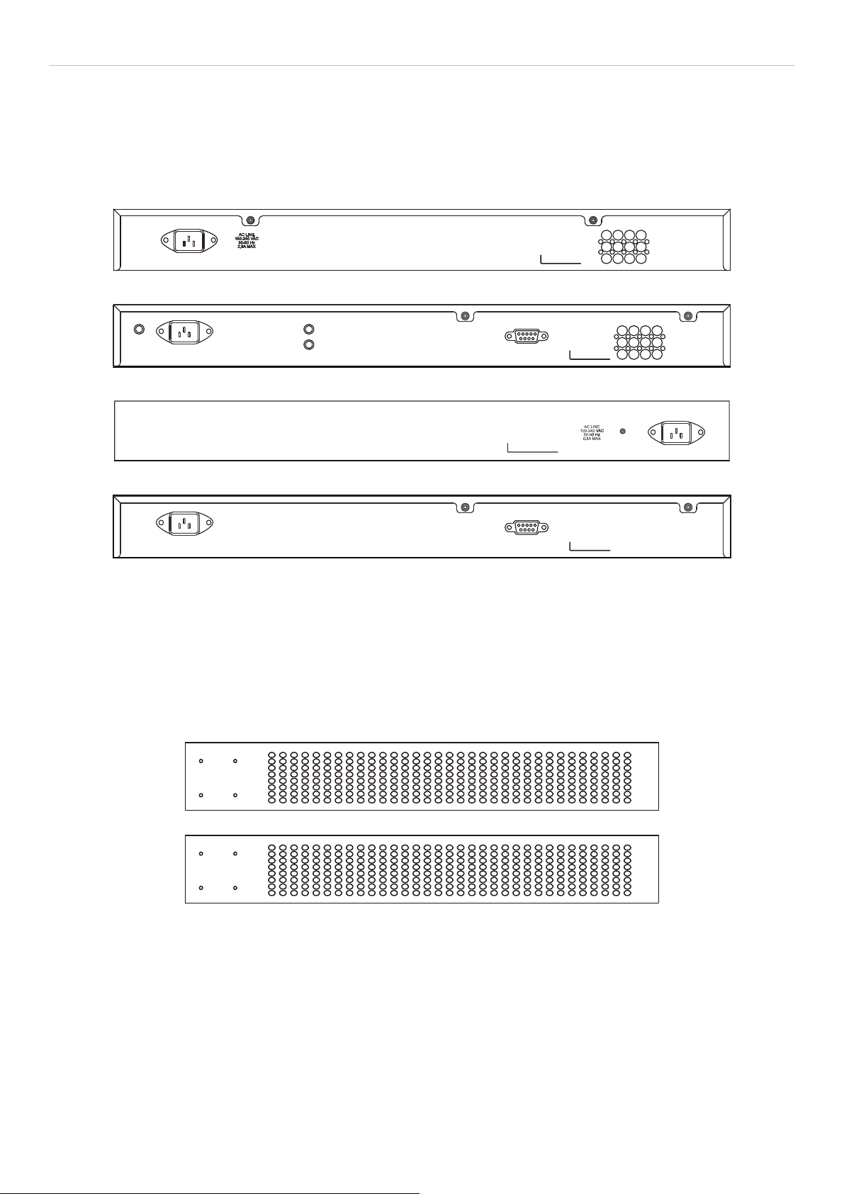
Rear Panel Description
The rear panel of the Switch contains an AC power connector. The AC power connector is a standard three-pronged
connector that supports the power cord. Plug-in the female connector of the provided power cord into this socket, and the
male side of the cord into a power outlet. The Switch automatically adjusts its power setting to an y supply voltage in the
range from 100 ~ 240 VAC at 50 ~ 60 Hz. The rear panel of the DES-3052/DES-3052P contains one female DCE RS 232 DB-9 console port.
Figure 1- 8. Rear panel view of the DES-3028P
AC LINE
100-240 VAC
50-60 Hz
5A MAX
Console
Figure 1- 9. Rear panel view of the DES-3052P
Figure 1- 10. Rear panel view of the DES-3028G/DES-3028
AC LINE
100-240 VAC
50-60 Hz
0.5A MAX
Console
Figure 1- 11. Rear panel view of the DES-3052
Side Panel Description
The left and right-hand panel of the DES-3028G/DES-3028/DES-3052 Switches contain heat vents. The heat vents are used to
dissipate heat. Do not block these openings, and leave at least 6 inches of space at the rear and sides of the Switch for proper
ventilation. Be reminded that without proper heat dissipation and air circulation, system components might overheat, which could
lead to system failure.
Figure 1- 12. Side panels of the DES-3028G/DES-3028/DES-3052
The sides of the DES-3028P have heat vents to serve to dissipate heat. Do not block these openings, and leave at least 6 inches of
space at the rear and sides of the Switch for proper ventilation. Be reminded that without proper heat dissipation and air
circulation, system components might overheat, which could lead to system failure.
6

DES-3028 DES-3028P DES-3028G DES-3052 DES-3052P Layer 2 Fast Ethernet Managed Switch
Figure 1- 13. Side panels of the DES-3028P
The left-hand side panel of the DES-3052P Switch contains a system fan and ventilation along the entire right side. The system
fan is used to dissipate heat. Do not block these openings on either side of the Switch. Leave at least 6 inches of space at the rear
and sides of the Switch for proper ventilation. Be reminded that without proper heat dissipation and air circulation, system
components might overheat, which could lead to system failure.
Figure 1- 14. Side panels of the DES-3052P
Gigabit Combo Ports
In addition to the 24 (or 48) 10/100 Mbps ports, the Switch features two Gigabit Ethern et Combo ports. These two ports are
1000BASE-T copper ports (provided) and Mini-GBIC ports (optional). See the diagram below to view the two Mini-GBIC port
modules being plugged into the Switch. Please note that although these two front panel modules can be used simultaneously, the
ports must be different. The GBIC port will always have the highest priority.
Figure 1- 15. Inserting the Mini-GBIC modules into the DES-3028/28P/28G/52/52P Switch
7

DES-3028 DES-3028P DES-3028G DES-3052 DES-3052P Layer 2 Fast Ethernet Managed Switch
Figure 1- 16. Installing the Mini-GBIC Module
Installing the SFP ports
The DES-3028/28P/28G/52/52P Switches are equipped with SFP (Small Form Factor Portable) ports, which are to be used with
fiber-optical transceiver cabling in order to uplink various other networking devices for a gigabit link that may span great
distances. These SFP ports support full-duplex transmissions, have auto-negotiation and can be used with the DEM-310GT
(1000BASE-LX), DEM-311GT (1000BASE-SX), DEM-210 (Single Mode 100BASE-FX), DEM-211 (Multi Mode 100BASEFX), DEM-314GT (1000BASE-LH), DEM-315GT (1000BASE-ZX), DEM-330T/R (WDM) and DEM-331T/R (WDM)
transceivers. See the figure below for installing the SFP ports in the Switch.
Figure 1- 17. Inserting the fiber-optic transceivers into the DES-3028/28P/28G/52/52P Switch
8

DES-3028 DES-3028P DES-3028G DES-3052 DES-3052P Layer 2 Fast Ethernet Managed Switch
Section 2
Installation
Package Contents
Before You Connect to the Network
Installing the Switch without the Rack
Rack Installation
Power On
Package Contents
Open the shipping carton of the Switch and carefully unpack its contents. The carton should contain the following items:
One Stand-alone Switch
One AC power cord
This Manual on CD
Mounting kit (two brackets and screws)
Four rubber feet with adhesive backing
DCE RS-232 console cable
If any item is missing or damaged, please contact your local D-Link Reseller for replacement.
Before You Connect to the Network
The site where you install the Switch may greatly affect its performance. Please follow these guidelines for setting up the Switch.
Install the Switch on a sturdy, level surface that can support at least 4.24kg (9.35lbs) of weight. Do not place heavy
objects on the Switch.
The power outlet should be within 1.82 m e t e rs (6 feet) of the Swit ch .
Visually inspect the power cord and see that it is fully secured to the AC/DC power port.
Make sure that there is proper heat dissipation from and adequate ventilation around the Switch. Leave at least 10 cm
(4 inches) of space at the front and rear of the Switch for ventilation.
Install the Switch in a fairly cool and dry place for the acceptable temperature and humidity operating ranges.
Install the Switch in a site free from strong electromagnetic field generators (such as motors), vibration, dust, and
direct exposure to sunlight.
When installing the Switch on a level surface, attach the rubber feet to the bottom of the device. The rubber feet
cushion the Switch, protect the casing from scratches and prevent it from scratching other surfaces.
9

DES-3028 DES-3028P DES-3028G DES-3052 DES-3052P Layer 2 Fast Ethernet Managed Switch
Installing the Switch without the Rack
When installing the Switch on a desktop or shelf, the rubber feet included with the Switch should first be attached. Attach the se
cushioning feet on the bottom at each corner of the device. Allow enough ventilation space between the Switch and any other
objects in the vicinity.
Figure 2 - 1. Prepare Switch for installation on a desktop or shelf
Installing the Switch in a Rack
The Switch can be mounted in a standard 19" rack. Use the following diagrams to guide you.
Figure 2 - 2. Fasten mounting brackets to Switch
Fasten the mounting brackets to the Switch using the screws provided. With the brackets attached securely, users can mount the
Switch in a standard rack as shown in the next figure.
10
DES-3028 DES-3028P DES-3028G DES-3052 DES-3052P Layer 2 Fast Ethernet Managed Switch
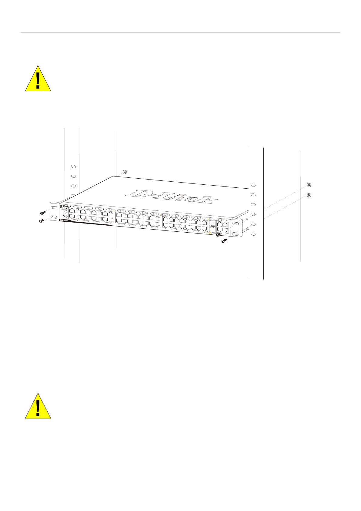
Mounting the Switch in a Standard 19" Rack
CAUTION: Installing systems in a rack without the front and side stabilizers installed could cause the
rack to tip over, potentially resulting in bodily injury under certain circumstances. Therefore, always
install the stabilizers before installing components in the rack. After installing components in a rack, do
not pull more than one component out of the rack on its slide assemblies at one time. The weight of
more than one extended component could cause the rack to tip over and may result in injury.
Figure 2 - 3. Installing Switch in a rack
Power on AC Power
Plug one end of the AC power cord into the power connector of the Switch and the other end into the local power source outlet.
After the Switch is powered on, the LED indicators will momentarily blink. This blinking of the LED indicators represents a reset
of the system.
Power Failure
For AC power supply units, as a precaution, in the event of a power failure, unplug the Switch. When power has resumed, plug the
Switch back in.
CAUTION: Installing systems in a rack without the front and side stabilizers installed could cause the
rack to tip over, potentially resulting in bodily injury under certain circumstances. Therefore, always
install the stabilizers before installing components in the rack. After installing components in a rack, do
not pull more than one component out of the rack on its slide assemblies at one time. The weight of
.
more than one extended component could cause the rack to tip over and may result in injury.
11
DES-3028 DES-3028P DES-3028G DES-3052 DES-3052P Layer 2 Fast Ethernet Managed Switch
Section 3
Connecting the Switch
Switch to End Node
Switch to Hub or Switch
Connecting to Network Backbone or Server
NOTE: All 10/100/1000Mbps NWay Ethernet ports can support both MDIII and MDI-X connections.
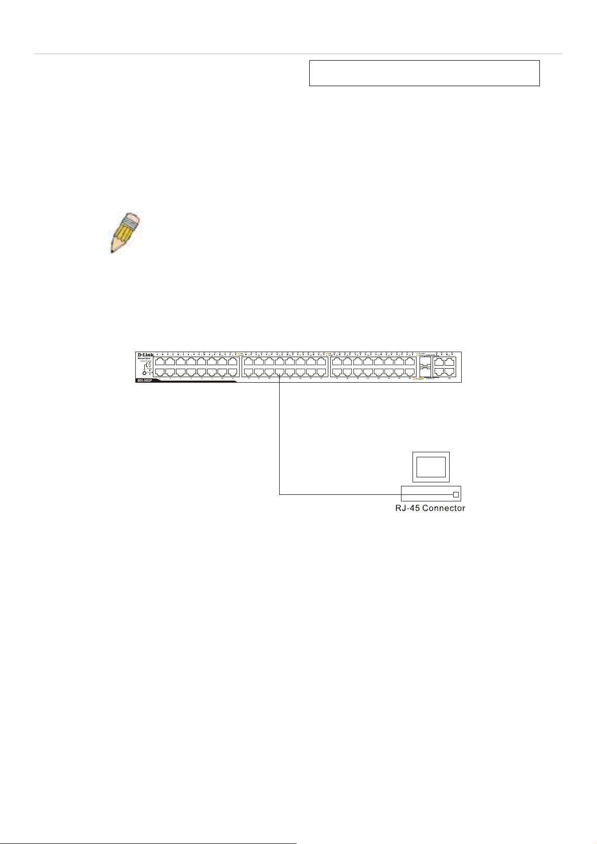
Switch to End Node
End nodes include PCs outfitted with a 10, 100 or 1000 Mbps RJ 45 Ethernet/Fast Ethernet Network Interface Card (NIC) and
most routers. An end node can be connected to the Switch via a twisted-pair Category 3, 4, or 5 UTP/STP cable. The end node
should be connected to any of the ports of the Switch.
Figure 3- 1. Switch connected to an end node
The Link/Act LEDs for each UTP port will light green or amber when the link is valid. A blinking LED indicates packet activity
on that port.
12

DES-3028 DES-3028P DES-3028G DES-3052 DES-3052P Layer 2 Fast Ethernet Managed Switch
Switch to Hub or Switch
These connections can be accomplished in a number of ways using a normal cable.
A 10BASE-T hub or switch can be connected to the Switch via a twisted-pair Category 3, 4 or 5 UTP/STP cable.
A 100BASE-TX hub or switch can be connected to the Switch via a twisted-pair Category 5 UTP/STP cable.
A 1000BASE-T switch can be connected to the Switch via a twisted pair Category 5e UTP/STP cable.
A switch supporting a fiber-optic uplink can be connected to the Switch’s SFP ports via fiber-optic cabling.
Figure 3- 2. Switch connected to a normal (non-Uplink) port on a hub or switch using a straight or crossover
cable
NOTICE: When the SFP transceiver acquires a link, the associated integrated
10/100/1000BASE-T port is disabled.
13

DES-3028 DES-3028P DES-3028G DES-3052 DES-3052P Layer 2 Fast Ethernet Managed Switch
Section 4
Introduction to Switch Management
Management Options
Web-based Management Interface
SNMP-Based Management
Managing User Accounts
Command Line Console Interface through the Serial Port
Connecting the Console Port (RS-232 DCE)
First Time Connecting to the Switch
Password Protection
SNMP Settings
IP Address Assignment
Management Options
This system may be managed out-of-band through the console port on the front panel or in-band using Telnet. The user may also
choose the web-based management, accessible through a web browser.
Web-based Management Interface
After you have successfully installed the Switch, you can configure the Switch, monitor the LED panel, and display statistics
graphically using a web browser, such as Netscape Navigator (version 6.2.3 and higher) or Microsoft® Internet Explorer (version
6.0).
SNMP-Based Management
You can manage the Switch with an SNMP-compatible console program. The Switch supports SNMP version 1.0, version 2.0 and
version 3.0. The SNMP agent decodes the incoming SNMP messages and responds to requests with MIB objects stored in the
database. The SNMP agent updates the MIB objects to generate statistics and counters.
Connecting the Console Port (RS-232 DCE)
The Switch provides an RS-232 serial port that enables a connection to a computer or terminal for monitoring and configuring the
Switch. This port is a female DB-9 connector, implemented as a data terminal equipment (DTE) connection.
To use the console port, you need the following equipment:
A terminal or a computer with both a serial port and the ability to emulate a terminal.
A null modem or crossover RS-232 cable with a female DB-9 connector for the console port on the Switch.
To connect a terminal to the console port:
1. Connect the female connector of the RS-232 cable directly to the console port on the Switch, and tighten the captive
retaining screws.
2. Connect the other end of the cable to a terminal or to the serial connector of a computer running terminal emulation
software. Set the terminal emulation software as follows:
3. Select the appropriate serial port (COM port 1 or COM port 2).
4. Set the data rate to 9600 baud.
5. Set the data format to 8 data bits, 1 stop bit, and no parity.
6. Set flow control to none.
14

DES-3028 DES-3028P DES-3028G DES-3052 DES-3052P Layer 2 Fast Ethernet Managed Switch
7. Under Properties, select VT100 for Emulation mode.
8. Select Terminal keys for Function, Arrow, and Ctrl keys. Ensure that you select Terminal keys (not Windows keys).
NOTE: When you use HyperTerminal with the Microsoft® Windows® 2000 operating system, ensure that you have Windows 2000 Service Pack 2 or later installed. Windows 2000
Service Pack 2 allows you to use arrow keys in HyperTerminal's VT100 emulation. See
www.microsoft.com for information on Windows 2000 service packs.
9. After you have correctly set up the terminal, plug the power cable into the power receptacle on the back of the Switch.
The boot sequence appears in the terminal.
10. After the boot sequence completes, the console login screen displays.
11. If you have not logged into the command line interface (CLI) program, press the Enter key at the User name and
password prompts. There is no default user name and password for the Switch. The administrator must first create user
names and passwords. If you have previously set up user accounts, log in and continue to configure the Switch.
12. Enter the commands to complete your desired tasks. Many commands require administrator-level access privileges. Read
the next section for more information on setting up user accounts. See the DES-3028/28P/28G/52/52P CLI Manual on
the documentation CD for a list of all commands and additional information on us ing the CLI.
13. When you have completed your tasks, exit the session with the logout command or close the emulator program.
14. Make sure the terminal or PC you are using to make this connection is configured to match these settings.
If you are having problems making this connection on a PC, make sure the emulation is set to VT-100. You will be able to set the
emulation by clicking on the File menu in you HyperTerminal window, clicking on Properties in the drop-down menu, and then
clicking the Settings tab. This is where you will find the Emulation options. If you still do not see anything, try rebooting the
Switch by disconnecting its powe r s u ppl y .
Once connected to the console, the screen below will appear on your console screen. This is where th e user will enter commands
to perform all the available management functions. The Switch will prompt the user to enter a user name and a password. Upon
the initial connection, there is no user name or password and therefore just press enter twice to access the command line interface.
DES-3028G Fast Ethernet Switch Command Line Interface
Firmware: Build 2.00.B26
Copyright(C) 2009 D-Link Corporation. All rights reserved.
UserName:
Figure 4- 1. Initial screen after first connection
15

DES-3028 DES-3028P DES-3028G DES-3052 DES-3052P Layer 2 Fast Ethernet Managed Switch
First Time Connecting to the Switch
The Switch supports user-based security that can allow you to prevent unauthorized users from accessing the Switch or changing
its settings. This section tells how to log onto the Switch.
NOTE: The passwords used to access the Switch are case-sensitive; therefore, "S" is
not the same as "s."
When you first connect to the Switch, you will be presented with the first login screen.
NOTE: Press Ctrl+R to refresh the screen. This command can be used at any time to
force the console program in the Switch to refresh the console screen.
Press Enter in both the Username and Password fields. You will be given access to the command prompt DES-3028G:4# shown
below:
There is no initial username or password. Leave the Username and Password fields blank.
DES-3028G Fast Ethernet Switch Command Line Interface
Firmware: Build 2.00.B26
Copyright(C) 2009 D-Link Corporation. All rights reserved.
UserName:
PassWord:
DES-3028G:4#
Figure 4- 2. Command Prompt
NOTE: The first user automatically gets Administrator level privileges. It is recommended to
create at least one Admin-level user account for the Switch.
Password Protection
The Switch does not have a default user name and password. One of the first tasks when settings up the Switch is to create user
accounts. Once logged in using a predefined administrator-level user name, users will have privileged access to the Switch's
management software.
After your initial login, define new passwords for both default user names to prevent unauthorized access to the Switch, and
record the passwords for future reference.
To create an administrator-level account for the Switch, follow these steps:
At the CLI login prompt, enter create account admin followed by the <user name> and press the Enter key.
The switch will then prompt the user for a password. Type the <password> used for the administrator account being
created and press the Enter key.
Again, the user will be prompted to enter the same password again to verify it. Type the same password and press
the Enter key.
Successful creation of the new administrator account will be verified by a Success m essage.
16
Loading...