


 Loading...
D-Link SecuriCam
DCS-900W
Internet Camera
Manual
Version 1.20
Building Networks for People
(04/01/04)
Contents |
|
Package Contents ............................................................... |
3 |
Introduction .......................................................................... |
4 |
Hardware Installation ............................................................ |
9 |
Security .............................................................................. |
10 |
Using the Setup Wizard ..................................................... |
11 |
DCS-900W Configuration .................................................. |
17 |
Installing the DCS-900W Behind a Router ........................ |
27 |
IPView Lite Application Installation .................................... |
41 |
IPView Lite ......................................................................... |
46 |
Uninstall IPView Lite Application ........................................ |
78 |
Appendix (FAQ, Troubleshooting, Time Zone Table, |
|
Active X Installation). ............................................................ |
80 |
Technical Specifications .................................................... |
93 |
Contacting Technical Support ............................................ |
95 |
Warranty & Registration .............. .................................... ... |
96 |
2
Package Contents
Package Contents:
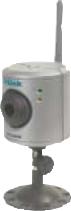
•One DCS-900W Internet Camera
•One Installation CD-ROM
•One 802.11b Antenna
•One AC power adapter
•One Camera Stand
•One Category 5 Ethernet Cable
If any of the above items are missing, please contact your reseller.
System Requirements:
Local Area Network: 10Base-T Ethernet or 100BaseTX Fast Ethernet Wireless Local Area Network: 802.11b Wireless Router or Access Point Recommended: PC, Mac or Notebook to access the Internet Camera
Web Configuration
•Java Enabled and Compliant Web Browser (recommended)
•CPU: Pentium III, 450MHz or above
•Memory Size: 128MB recommended
•VGA card resolution: 800x600 or above
IPView Lite Configuration
•Windows XP, Me, 2000, 98SE
•CPU: Pentium III, 450MHz or above
•Memory Size: 128MB (256MB recommended)
•VGA card resolution: 800 x 600 or above
3
Introduction
Congratulations on your purchase of the DCS-900W Internet Camera! The DCS-900W is a versatile and unique solution for your small office or home. Unlike a PC Camera, the DCS-900W is a stand-alone system with a built-in CPU and Web server that transmits high quality video images for monitoring. The DCS-900W can be accessed remotely, and controlled from any PC/Notebook over the Intranet or Internet via a web browser. The simple installation procedure and intuitive web-based interface offer easy integration with your Ethernet/Fast Ethernet or 802.11b wireless network. The DCS900W also comes with remote monitoring capability for a complete and cost-effective home security solution.
Features & Benefits
Simple to Use
The DCS-900W is a stand-alone system with a built-in CPU, requiring no special hardware or software such as PC frame grabber cards. The DCS-900W supports both ActiveX mode for Internet Explorer and Java mode for Internet Explorer and Netscape Navigator. All that is required is a computer with current Web browser software.
Supports a Variety of Platforms
Supporting TCP/IP networking, HTTP, and other Internet related protocols, the DCS900W can be utilized in a mixed operating system environment such as Windows, Unix, and Macintosh. It can also be integrated easily into other Internet/Intranet applications because of its standards-based features.
802.11b Wireless or Ethernet/Fast Ethernet Support
The DCS-900W offers both 802.11b wireless and Ethernet/Fast Ethernet connectivity, making the DCS-900W easy to integrate into your existing network environment. The DCS-900W works with a 10Mbps Ethernet based network or 100Mbps Fast Ethernet based network for traditional wired environments and works with 802.11b routers or access points for added flexibility.
4
Features & Benefits (continued)
Web Configuration
Using a standard Web browser, Administrators can configure and manage the Internet Camera directly from its own Web page via the Intranet or Internet. This means you can access your DCS-900W at anytime from anywhere in the world!
Remote Monitoring Utility
The IPView Lite application adds enhanced features and functionality for the Internet Camera and allows administrators to configure and access the Internet Camera from a remote site via Intranet or Internet. Other features include image monitoring, recording images to a hard drive, enabling motion detection, updating firmware, viewing up to 4 cameras on one screen, and taking snapshots.
Broad Range of Applications
With today’s high-speed Internet services, the Internet Camera can provide the ideal solution for live video images over the Intranet and Internet for remote monitoring. The Internet Camera allows remote access from a Web browser for live image viewing and allows the administrator to manage and control the Internet Camera at anytime, from anywhere in the world. Many applications exist, including industrial and public monitoring of homes, offices, banks, hospitals, child-care centers, and amusement parks.
5
Connections
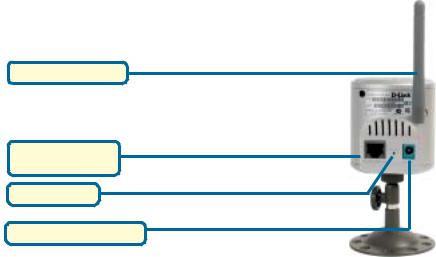
Rear Panel view
802.11b Antenna
Ethernet Cable
Connector
Reset Button
DC Power Connector
802.11b Antenna
The DCS-900W features an 802.11b wireless antenna for 802.11b wireless connectivity to your existing wireless network. The DCS-900W can be used in conjuction with an 802.11b compliant access point or router.
EthernetCable Connector
The DCS-900W features an RJ-45 connector for connections to 10Base-T Ethernet cabling or 100Base-TX Fast Ethernet cabling (which should be Category 5 UTP cable). The port supports the NWay protocol, allowing the DCS-900W to automatically detect or negotiate the transmission speed of the network.
DC Power Connector
The DC power input connector is labeled DC 5V with a single jack socket to supply power to the DCS-900W.
Reset Button
Reset will be initiated when the reset button is pressed once and Power LED begins to flash.
Factory Reset will be initiated when the reset button is pressed continuously for three seconds or when the Power LED begins to light up. Release the reset button and the Power LED will begin to flash indicating that the DCS-900W’s settings are reverting back to the factory settings. The IP address will also return to the default setting of 192.168.0.20.
6
Connections (continued)
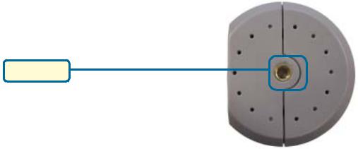
Bottom Panel view
Stand Mount
7
LEDS
LED stands for Light-Emitting Diode.
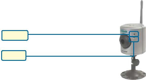
Front view
Power LED
LAN LED
Power LED
The Power LED is positioned on the right side of the DCS-900W lens. Steady green confirms that the DCS-900W is powered ON.
Note:
There are three settings for the Power LED for monitoring purposes: Normal / Off / Dummy. Please refer to the DCS-900W Camera Configuration section on P. 24 for detailed information and usage.
LAN LED
The LAN LED is positioned on the right side of the DCS-900W’s lens. It is located below the Power LED.
Steady orange confirms a good connection to the LAN.
Depending on the data traffic, the LED will begin to flash to indicate that the DCS-900W is receiving/transceiving from/to the LAN network.
8
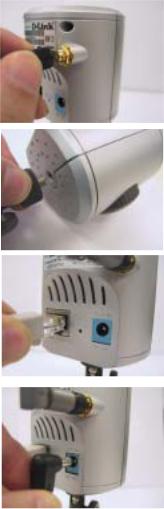
Hardware Installation
Attach the Antenna
Locate the antenna included with your DCS-900W and attach it to the antenna connector located on the back of the DCS-900W.
Attach the Swivel Stand
Locate the stand mount on the bottom of the DCS900W and screw on the swivel stand.
Connect the Ethernet Cable
Connect the included Ethernet cable to the network cable connector located on the back panel of the DCS-900W and attach it to the network.
Attach the External Power Supply
Attach the external power supply to the DC power input connector located on the rear panel of the
DCS-900W and connect it to your local power supply. Note: Power source is confirmed when the green LED Power Indicator located to the right of the lens on the DCS-900W is illuminated.
Network Connectivity is confirmed when the orange LED Indicator on the DCS-900W located below the Power LED is illuminated.
9
Security
To ensure the highest security and prevent unauthorized usage of the DCS-900W, the Administrator has the exclusive privilege to create all users. The DCS-900W supports multi-level password protection/access that can be restricted by the Administrator for defined users who have a User Name and User Password.
The Administrator can release a public User Name and Password so that when remote users access the DCS-900W they will be allowed to view the images transmitted by the DCS-900W.
Note:
When the DCS-900W is used for the first time, it is highly recommended that the Administrator set the Admin ID and Admin Password to constrain user access to the DCS-900W since the Default settings are Null String (no password). Once the ID and Password are defined, only the Administrator has access to the management of the DCS-900W. This procedure should be done as soon as possible since the security features of the DCS-900W will not be enabled until the Admin ID and Admin Password is defined.
10
Using the Setup Wizard
Follow the simple steps below to run the Setup Wizard to guide you quickly through the installation process.
Insert the D-Link DCS-900W CD into your CD-ROM drive.
Click Install
Software
Click Install
Wizard
Click Next
11
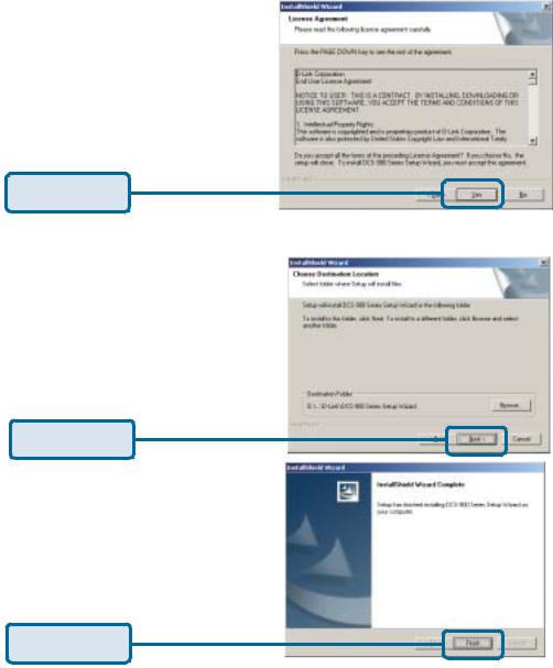
Using the Setup Wizard (continued)
Click Yes
Click Next
Click Finish
12
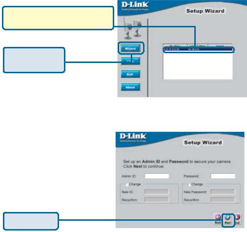
Using the Setup Wizard (continued)
To run the Setup Wizard, click on
Start->Programs->DCS-900W Series Setup
Wizard.
Your camera’s IP Address will be displayed here if it is valid.
Click Wizard to begin
You must change the Admin ID and Password immediately to protect your camera against unauthorized access. By default, the Admin ID and Password are blank. To change the Admin ID and Password, select both Change boxes and enter a New ID and New Password.
Click Next
13
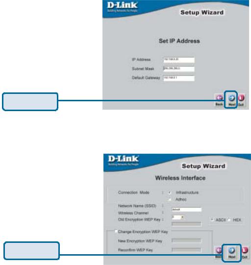
Using the Setup Wizard (continued)
The IP Address, Subnet Mask of your camera and Gateway must correspond with your network settings for you to access the camera. If you are unsure of what these settings should be, please check with your network administrator.
Click Next
The Connection Mode depends on how your camera is connected to your network. Click Infrastructure for use with a router or Adhoc for a peer-to-peer connection. The Network Name, Wireless Channel, and Encryption Keys MUST correspond with your wireless network settings for the camera to work.
Click Next
14
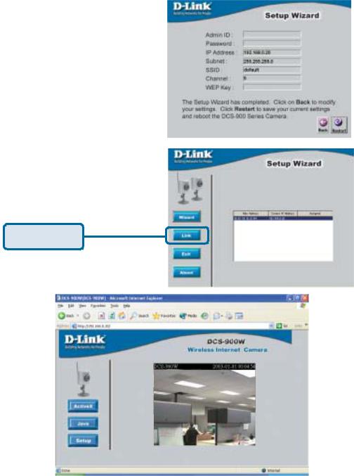
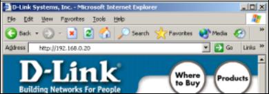
Using the Setup Wizard (continued)
If you need to make any changes, click Back to modify your camera settings. Otherwise, click Restart to save and apply your settings.
Your setup is now complete! Click Link to launch your Web browser and view your images.
Click Link
15

Using the Setup Wizard (continued)
If you change any of the default settings in the Setup Wizard, the following screens may appear:
This screen appears if the default IP Address of the camera (192.168.0.20) does not correspond with your local area network settings. You must assign an IP address for your camera that corresponds to your network’s IP addressing scheme.
Click Yes
By default, the Admin ID and Password are blank. If you are running this Setup Wizard for the first time, leave both Admin ID and Password fields blank and simply click OK to continue. If you changed the Admin ID and Password, enter them and click OK to continue.
Click OK
The IP Address of your camera must correspond with your network settings for you to access the camera. If you are unsure of what these settings should be, please check with your network administrator.
Click OK
16
DCS-900W Configuration
Web Configuration
After completing the Setup Wizard, you are ready to use your camera. The Web configuration utility is designed to easily access and configure your DCS-900W.
If you would like to open the configuration page from a Web Browser, enter the IP address that you assigned to your DCS-900W.
Note:
The PC’s IP address must correspond with the DCS-900W’s IP address in the same segment (i.e. PC=192.168.0.5, Camera=192.168.0.20) for the two devices to communicate. For instructions on how to do this, please access instructions for installing any of the D-Link Broadband Gateway products from support.dlink.com/
products.
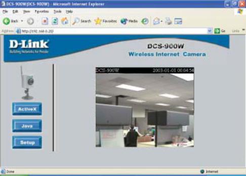
Home Screen
After the camera’s IP address is entered in the Browser, the DCS-900W Home screen will appear with a still image from your camera. There will be three options to choose from to set up and view your Internet Camera:
!ActiveX
!Java
!Setup
17
DCS-900W Configuration (continued)
Configuration
Click on Setup from the Home screen to access the settings required for the DCS900W.
There will be several options in the Configuration page to choose from to setup your DCS-900W and they are as follows:
Advanced
•System
•Video
Tools
•Admin
•Time
•Default
Status Help
18
DCS-900W Configuration (continued)
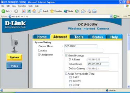
Advanced > System
The System menu allows you to configure and set up your DCS-900W for operation. If you already set up your camera using the Setup Wizard, you may view/change your settings here.
To access the System menu, click on the Advanced Tab in the menu bar, then the System tab in the left hand bar and the System screen will appear as illustrated below:
19

DCS-900W Configuration (continued)
Advanced > System
Camera Name:
This field is used for entering a descriptive name for the camera. The default setting for the Camera Name is CS-xxxxxx, where xxxxxx are the last six digits of the MAC Address. The maximum length is 32 characters (Printable ASCII).
Location:
This field is used for entering a descriptive name for the location used by the DCS900W.
IP Assignment:
Important Information
Access to the Internet Camera is gained by assigning a proper IP Address. Please make sure to use a vacant IP address when you assign the IP Address for the Internet Camera. This will prevent IP Address conflicts.
There are two options to select from the IP Assignment, either Manually Assign or
Assign Automatically Using.
Manually Assign
You can click Manually Assign and directly enter a valid IP Address for your camera. Remember that your camera’s IP Address must correspond to your network settings if you wish to change it here.
The default settings are as follows:
!Default IP – 192.168.0.20
!Subnet Mask – 255.255.255.0
!Default Gateway – 0.0.0.0
20
DCS-900W Configuration (continued)
Advanced > System
Assign Automatically Using
Important
This options is recommended only for advanced users and network administrators since it may be difficult to determine the IP Address of the unit after the IP Address has been automatically asssigned. It is recommended that an IPAddress be assigned manually.
If your network is using RARP, BOOTP, or DHCP Server you can Click Assign Automatically Using and click on RARP, BOOTP or DHCP. Under this setting the DCS-900W will automatically assign an IP Address from the RARP, BOOTP or DHCP Server. Each time the DCS-900W starts up, be sure the RARP, BOOTP or DHCP Server is set up to assign a static IP to your DCS-900W.
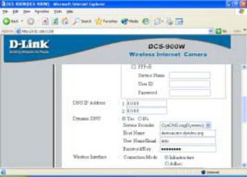
If your application requires direct connection from an ADSL modem through the DCS900W’s RJ-45 LAN port and you also have an ISP PPPoE account, click on PPPoE and enter the Service Name, User ID and Password into the respective fields.
The DCS-900W will get an IP Address from the ISP each time it starts up.
21
DCS-900W Configuration (continued)
Advanced > System
DNS IP Address:
DNS (Domain Name Service) is an Internet service that translates domain names (ie. www.dlink.com) into IP Addresses (ie. 192.168.0.20). The DNS IP Address can be obtained from your ISP.
Dynamic DNS
The DCS-900W supports Dynamic DNS which means that you can obtain and assign an easy to remember static address for your camera like www.mycamera.com through a free service such as www.dyndns.org. This means that no matter how often your camera’s IP changes, you will always be able to access your camera using your unique assigned name such as www.mycamera.com.
22

DCS-900W Configuration (continued)
Advanced > System
Wireless Interface:
Connection Mode:
Use the Connection Mode to determine the type of wireless communication for the Internet Camera. There are three choices: Infrastructure mode, 802.11 Adhoc mode and Adhoc mode. The default setting for the Connection Mode is Infrastructure.
To enable WEP Encryption, first decide which WEP key format will be applied. Click on the ASCII or HEX check box to select the type of format, then input the WEP key. To Confirm the WEP key you must enter the data once again in the Confirm WEP Key field.
ASCII input format
ASCII format interprets each character as an eight-bit value. All unaccented upperand lower-case Western European characters that can be input through your keyboard’s typing zone are valid. To set up a 64-bit WEP key, input 5 ASCII characters, for example, ‘dlink’. To setup 128-bit WEP key, input 13 ASCII characters, for example, ‘dlinkcamera10’. This results in bit counts of 40 and 104, respectively; the Internet Camera will automatically pad your input to a bit count of 64 or 128.
23
DCS-900W Configuration (continued)
Advanced > System
HEX input format
HEX format interprets each pair of characters as an eight-bit value in hexadecimal (base 16) notation. Only the digits 0 through 9 and the letters A through F (in upper or lower case) are valid. To set up a 64-bit WEP key, input 10 numbers in HEX format, for example, ‘3132333435’, this is the same with the ASCII input ‘12345’. To set up a 128bit WEP key, input 26 numbers in HEX format, for example, ‘31323334353637383930313233’, this is the same with theASCII input ‘1234567890123’. This results in bit counts of 40 and 104, respectively; the Internet Camera will automatically pad your input to a bit count of 64 or 128.
In the Confirm WEP Key field, input the same characters that were inputted in the Encryption Code field.
Make sure the Encryption Code matches the Access Point’s encryption code when the Internet Camera is connected in Infrastructure mode. Your PC/Notebook’s encryption code also needs to match the encryption code used by the Internet Camera in either Infrastructure mode or Ad-hoc mode.
By default, an Encryption key is not assigned to the DCS-1000W. Therefore, to secure the wireless transmission be sure to enable the Encryption Key by entering the relevant data.
Note:
Be sure to carefully input and document the Encryption Code; input errors will cause the communication link to fail.
LED Control:
The LED control allows you to set up the LED illumination as desired. This feature provides flexibility when surveillance activity is ON.There are three options as follows:
!Normal
Power -LED indicator is steady ON.
LAN- When LAN activity is present, the LED indicator will flash steadily
ON.
!OFF
Power - LED indicator is off.
LAN – LED indicator is off.
!Dummy
Power - LED indicator is steady ON.
LAN - LED indicator is ON with random flashing.
24
DCS-900W Configuration (continued)
Advanced > System
The default setting for the LED control is Normal. When you have configured the LED control the correct illumination will be applied after 1 minute.
Note: The three LED options allow the Administrator to customize the LEDs for discreet camera operation in surveillance scenarios. In Normal Mode, the LED indicator functions normally. Under Off Mode, the LED indicators are both OFF during active monitoring. In Dummy Mode, the LEDs are active and monitoring is either active or inactive.
Loading ActiveX From:
This field is used to specify the location of Xplug Control (ActiveX) plug-in program. Enter the information as required in .ocx format, for example: http://www.<your company>.com/ xplug.ocx where <your company> must be replaced with your company’s DNS server.
Instructions for installing ActiveX from the driver CD is included in this manual. Please refer to the Appendix.
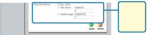
Open Second Port:
The Open Second Port option is used when multiple cameras are being installed on a network OR if you need to use a port other than the default Port 80. If you are installing only one camera and wish to use the default ports, you do not have to open a second port on your camera. If you are installing a camera behind a router, you must also open a port on your router for remote viewing of your camera. For detailed instructions on how to do this, please refer to the next section of this manual on how to install the DCS-900W with a router. For each additional camera that is installed, you must select the Open Second Port option and assign the approriate Web server and Transfer Image Ports for each camera to enable remote viewing.
For example, for a multiple camera installation, you can open the second port for each additional DCS-900W from Port 81 to Port 85 as follows:
Internet Camera 1 – IP 192.168.0.101, second Web Port 81
Internet Camera 2 – IP 192.168.0.102, second Web Port 82
Internet Camera 3 – IP 192.168.0.103, second Web Port 83
Internet Camera 4 – IP 192.168.0.104, second Web Port 84
Internet Camera 5 – IP 192.168.0.105, second Web Port 85
25
DCS-900W Configuration (continued)
Advanced > System
Note: If you are installing multiple DCS-900W and wish to use the default 192.168.0.20 address, remember to assign this address to the LAST camera that you plan to install to avoid conflict of IP Address.
IMPORTANT: You MUST also set up your router/gateway for Port Mapping--this will enable remote viewing of multiple cameras via the Internet. Please refer to your router’s instruction manual on how to open up ports. For additional help on configuring your camera to work with your router, please refer to the next section on setting up your camera for use with a router.
Apply/Cancel:
After making sure all your settings are correct, click on the Apply button to store the settings. You can alternatively click on the Cancel icon to restore all settings to the values last saved to or retrieved from the DCS-900W.
26
DCS-900W Configuration (continued)
Installing the DCS-900W Behind a Router
Single Camera Installation
If you are installing a single camera on your network the installation is an easy 4–step procedure:
1)Identify Your Camera on the Network
2)Assign a Local IP Address for Your Camera
3)Determine Your Router’s WAN IP Address (Enable Remote Viewing)
4)Open Virtual Server Ports for Your Router (Enable Remote Viewing)
Multiple Camera Installation
If you are installing multiple cameras on your network, the installation is an easy 5- step procedure:
1)Identify Your Camera on the Network
2)Assign a Local IP Address for Your Camera
3)Open a Second Port on the Camera
4)Determine Your Router’s WAN IP Address (Enable Remote Viewing)
5)Open Virtual Server Ports for Your Router (Enable Remote Viewing)
27

DCS-900W Configuration (continued)
Installing the DCS-900W Behind a Router
1) Identify Your Camera on the Network
Once you are logged into the camera via a web browser on your network PC,click on the Advanced Tab, and select System. Enter a unique Camera Name and Location. These settings are important if you are installing several cameras on your network.
Enter a
Unique camera name and location
IdentifyYourCamera onYour Network
2) Assign a Local IP Address for Your Camera
A Local IP Address is required to configure your camera and to view your camera within your local (home) network. You may use the default camera IP
Address of 192.168.0.20. If you wish to use a different IP Address, be sure that the camera settings correspond to your network settings. The Default Gateway will be the IP Address of your router’s Local IP Address(i.e.192.168.0.1 if you are using a D- Link router)
Enter a valid IP address for your camera.
Assign a Local IPAddress
28
DCS-900W Configuration (continued)
Installing the DCS-900W Behind a Router
Assigning and opening second port in the DCS-900W
( For Installing Multiple Cameras)
Opening ports will allow users to view the camera via the Internet. The ports that are opened must be unique for each camera in order to successfully view the images remotely.
3) Open Second Port
The Open Second Port option is used when multiple cameras are being installed on a network OR for using a port other than the default port for image viewing. For each additional camera that is installed, you must select the Open Second Port Option and assign the appropriate Web server and Transfer Image ports for each camera to enable remote viewing.
By default, ports 80 (Web server port) is open. If these ports are available for use, you DO NOT have to open a second port and can proceed to the next section. If port 80 is not available (for example, if you are already using port 80 to run a Web server or your ISP blocks access on port 80*) you MUST open a second port and designate a new Web server port (81, 82, 83,…etc) AND a new image transfer port (8482, 8483,…etc). IMPORTANT: Be sure to take note of these settings since these same settings will be used to configure your router.
Enter the desired port settings for your camera here.
Open a Second Port forYour Camera
*IMPORTANT NOTE: Some ISPs block traffic on commonly used ports like port 80 to conserve bandwidth. Be sure to check with your ISP so that you can open the appropriate ports accordingly. If your ISP does not pass traffic on port 80, you will need to change the Web server port the camera uses from 80 to something else, like 800. If you are behind a residential gateway, you will need to open the corresponding port on your gateway as well. Not all gateways are the same, please refer to your user’s manual for specific instructions on how to forward ports.
29
DCS-900W Configuration (continued)
Installing the DCS-900W Behind a Router
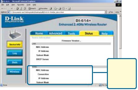
ROUTER SET-UP AND INSTALLATION
The following steps generally apply to any router that you have on your network. The D-Link DI-614+ is used as an example to clarify the configuration process.
Your WAN IP Address information will be listed here.
DetermineYourRouter’sWANIPAddress
Note: Because a dynamic WAN IP address can change from time to time depending on your ISP, you may want to obtain a Static IP address from your ISP. A Static IP address is a fixed IP address that will not change over time and will be more convenient for you to use to access your camera from a remote location. You can use DDNS to obtain an IP address, please refer to P.22 for more information.
30
Loading...