


Quick Installation Guide
HD Day & Night Vandal-Proof Fixed Dome Network Camera
This document will guide you through the basic installation process for your new D-Link Network Camera.
DCS-6511
Quick Installation Guide
Installationsanleitung
Guide d’installation
Guía de instalación
Guida di Installazione
Documentation also available on
CD and via the D-Link Website
DCS-6511_A1_QIG_v1.00(EU).indd 1 |
2010/10/13 11:19:53 |
|
|
|
|
|
|
|
|
|
|
|
|
|
|
|
|
|
|
|
|
|
|
|
|
|
|
|
|
|
|
|
|
|
|
|
|
|
|
|
|
|
|
|
|
|
|
|
|
|
|
|
|
|
|
|
|
|
|
|
|
|
|
|
|
|
|
|
|
|
|
|
|
|
|
|
|
|
|
|
|
|
|
|
|
|
|
|
|
|
|
|
|
|
|
|
|
|
|
|
|
|
|
|
|
|
|
|
|
|
|
|
|
|
|
|
|
|
|
|
|
|
|
|
|
|
|
|
|
|
|
|
|
|
|
|
|
|
|
|
|
|
|
|
|
|
|
|
|
|
|
|
|
|
|
|
|
|
|
|
|
|
|
|
|
|
|
|
|
|
|
|
|
|
|
|
|
|
|
|
|
|
|
|
|
|
|
|
|
|
|
|
|
|
|
|
|
|
|
|
|
|
|
|
|
|
|
|
|
|
|
|
|
|
|
|
|
|
|
|
|
|
|
|
|
|
|
|
|
|
|
|
|
|
|
|
|
|
|
|
|
|
|
|
|
|
|
|
|
|
|
|
|
|
|
|
|
|
|
|
|
|
|
|
|
|
|
|
|
|
|
|
|
|
|
|
|
|
|
|
|
|
|
|
|
|
|
|
|
|
|
|
|
|
|
|
|
|
|
|
|
|
|
|
|
|
|
|
|
|
|
|
|
|
|
|
|
|
|
|
|
|
|
|
|
|
|
|
|
|
|
|
|
|
|
|
|
|
|
|
|
|
|
|
|
|
|
|
|
|
|
|
|
|
|
|
|
|
|
|
|
|
|
|
|
|
|
|
|
|
|
|
|
|
|
|
|
|
|
|
|
|
|
|
|
DCS-6511_A1_QIG_v1.00(EU).indd 2 |
|
|
|
|
|
|
|
|
|
|
|
|
2010/10/13 11:19:54 |
||||||||||||||||||
DCS-6511 Quick Install Guide
This installation guide provides basic instructions for installing the DCS-6511 Network Camera on your network. For additional information about how to use the camera, please see the User’s Manual which is available on the CD included in this package or from the D-Link support website.
ENGLISH
Installation Steps
1.Verify the package contents against the list below.
2.Hardware Overview
3.SD Card Installation
4.Hardware Installation
5.Configuration with Wizard
6.Adjusting the lens 3-axis angel
1. Package Contents
DCS-6511 Network Camera
Manual and Software on CD-ROMQuick Install Guide
Power Adapter
AV & Power Cables
Security Wrench
CAT-5 Ethernet Cable
Extension AdapterCable Cover
Mounting Bracket and ScrewsRubber Plug
If any of the above items are missing, please contact your reseller.
Safety Notice:
Installation and servicing should be done by certified technicians so as to conform to all local codes and prevent voiding your warranty.
D-Link DCS-6511 Quick Install Guide |
1 |
|
|
|
|||
|
|
|
|
|
|
|
|
|
|
|
|
|
|
|
|
|
|
|
|
|
|
|
|
|
|
|
|
|
|
|
|
|
|
|
|
|
|
|
|
DCS-6511_A1_QIG_v1.00(EU).indd 1 |
2010/10/13 11:19:55 |
ENGLISH
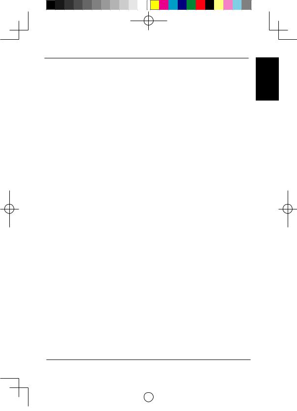
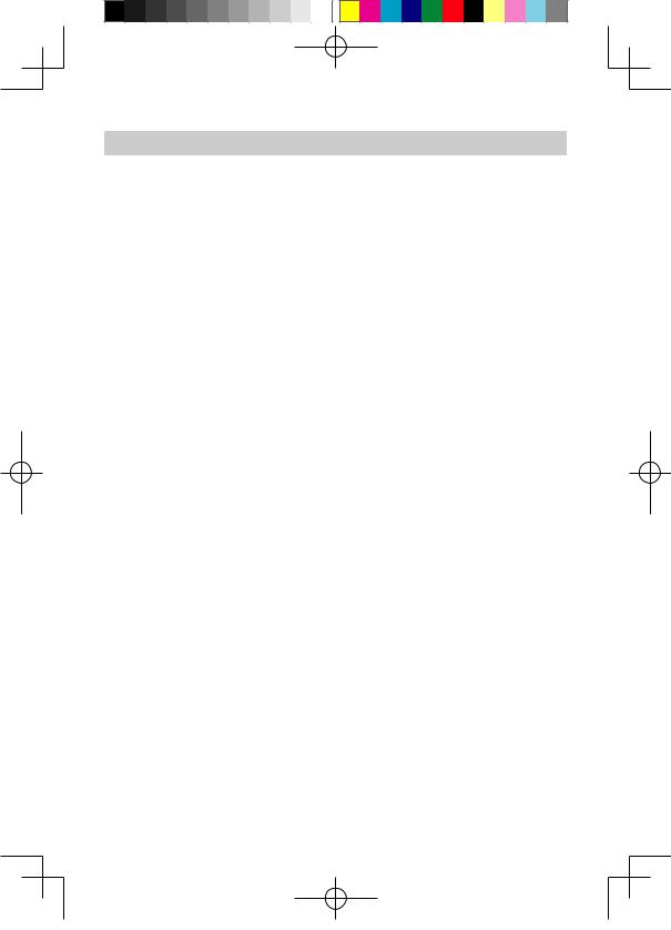
2. Hardware Overview
24 V Power Connector |
Connects to 24 V AC power |
Power Connector |
Connects to 12 V DC power |
Audio In
Connects to a microphone
Ethernet Jack
RJ-45 connector for Ethernet which can also be used to power the camera using Power over Ethernet (PoE)
DI/DO Wiring, 12V DC output
I/O connectors for external devices
Audio Out
Connects to speakers
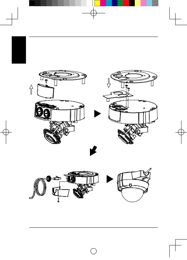
3. SD Card Installation
Disassemble the Camera
Open the camera enclosure by loosen the 4 screws. Lift the dome off the base of the camera.
Install the SD Card
Push the SD card into the camera with the gold contacts oriented towards the base of the camera. To eject the SD card, push the SD card into the slot.
|
|
2 |
|
|
D-Link DCS-6511 Quick Install Guide |
||
|
|
|
|
|
|
|
|
|
|
|
|
|
|
|
|
|
|
|
|
|
|
|
|
|
|
|
|
|
|
|
|
|
|
|
|
|
|
|
|
DCS-6511_A1_QIG_v1.00(EU).indd 2 |
2010/10/13 11:19:55 |
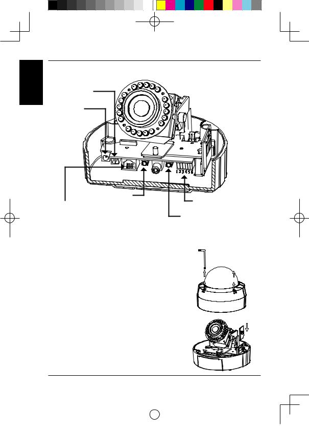
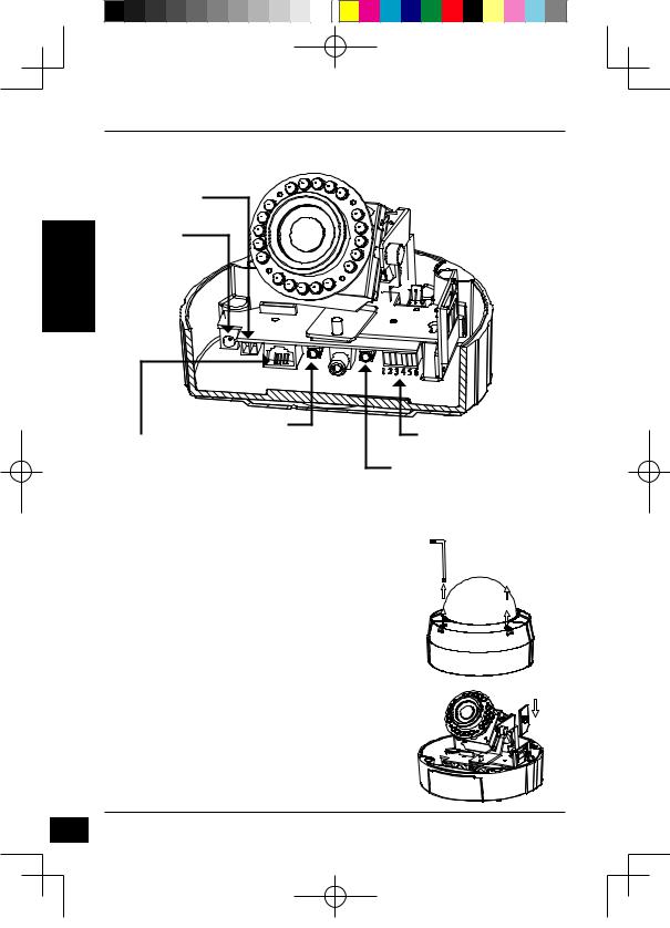
4. Standard Mounting Instructions
Mounting Installation
Please see the User Manual for detailed instructions regarding installation and mounting of the camera using a mounting bracket.
Style 1 - Concealed Cable Installation
Height: 23 mm (0.9 inches)
Diameter: 183 mm (7.2 inches)Weight: 400 g (0.9 lbs)
Figure 2.1
Figure 2.2
ENGLISH
D-Link DCS-6511 Quick Install Guide |
3 |
|
|
|
|||
|
|
|
|
|
|
|
|
|
|
|
|
|
|
|
|
|
|
|
|
|
|
|
|
|
|
|
|
|
|
|
|
|
|
|
|
|
|
|
|
DCS-6511_A1_QIG_v1.00(EU).indd 3 |
2010/10/13 11:19:56 |
ENGLISH
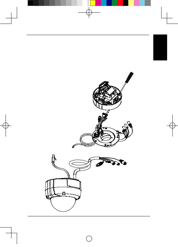
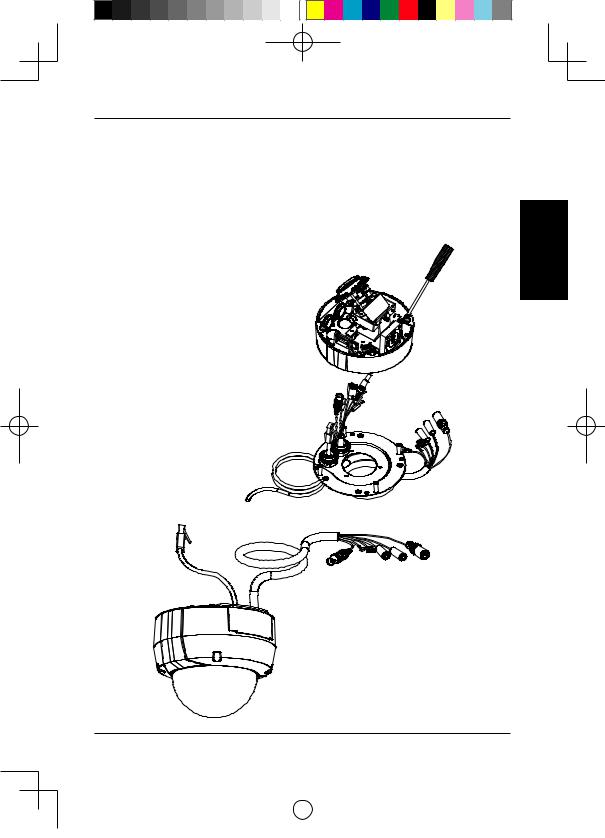
Style 2 - Exposed Cable Installation
Height: 23 mm (0.9 inches)
Diameter: 183 mm (7.2 inches)Weight: 400 g (0.9 lbs)
Figure 2.3 |
|
|
|
Figure 2.4 |
|
|
|
||
|
|
|
|
|
|
|
|
|
|
Figure 2.5 |
Figure 2.6 |
|
|
4 |
|
|
D-Link DCS-6511 Quick Install Guide |
||
|
|
|
|
|
|
|
|
|
|
|
|
|
|
|
|
|
|
|
|
|
|
|
|
|
|
|
|
|
|
|
|
|
|
|
|
|
|
|
|
DCS-6511_A1_QIG_v1.00(EU).indd 4 |
2010/10/13 11:19:56 |
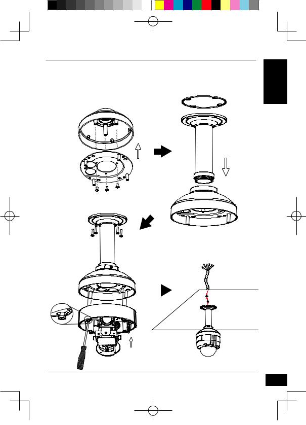
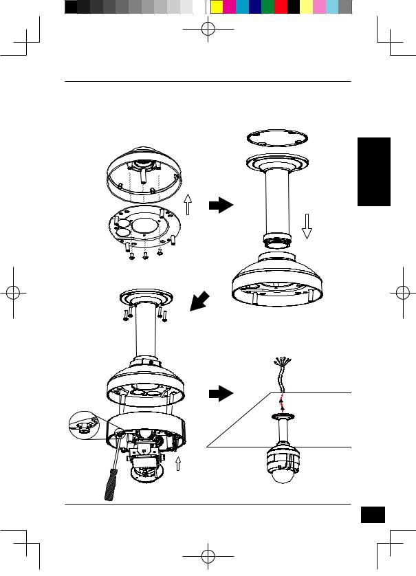
Pendant Mount (DCS-34-2)
Height: 201 mm (7.9 inches)Diameter: 150 mm (5.9 inches)
Weight: 665 g (1.45 lbs)
Rubber
Seal
Bracket
Cap
Pendant
Bracket
Mounting
Plate
Figure 3.1
Bracket
Cap
Figure 3.2
Figure 3.3 |
|
Figure 3.4 |
|
D-Link DCS-6511 Quick Install Guide
ENGLISH
5
DCS-6511_A1_QIG_v1.00(EU).indd 5 |
2010/10/13 11:19:56 |
ENGLISH
6
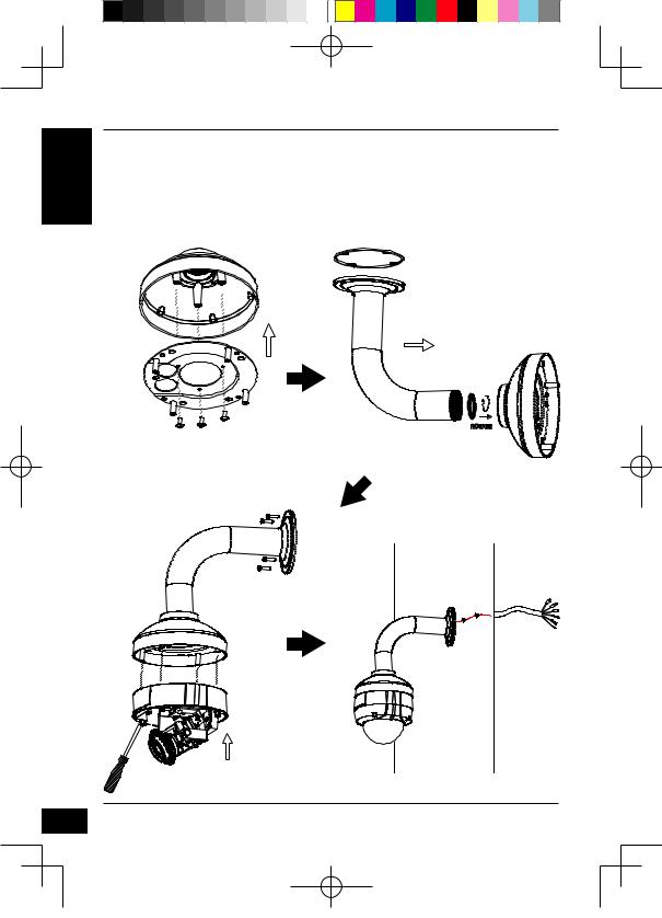
Bent Mount (DCS-34-3)
Height: 253 mm (9.96 inches)Diameter: 150 mm (5.9 inches)Weight: 770 g (1.7 lbs)
Bracket
Cap
Bent
Bracket
Mounting
Plate
Figure 4.1 |
Bracket Cap |
Figure 4.2
Bent
Bracket
Dome
Camera
Figure 4.3 |
Figure 4.4 |
D-Link DCS-6511 Quick Install Guide
DCS-6511_A1_QIG_v1.00(EU).indd 6 |
2010/10/13 11:19:56 |
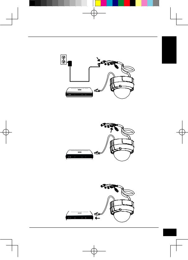
General Connection Using 12 V DC Power Adapter
1.Connect the network camera to a hub via an Ethernet cable.
2.Connect the supplied power cable from the camera to a power outlet.
General Connection Using 24 V AC Power Wiring
1.Connect the network camera to a hub via an Ethernet cable.
2.Connect the supplied power cable from the camera to a power source such as your building's emergency power.
Connection with a PoE Hub
If you are using a PoE hub, connect the IP camera to the hub via an Ethernet cable, which will provide transmission of both power and data over a single cable.
D-Link DCS-6511 Quick Install Guide
ENGLISH
7
DCS-6511_A1_QIG_v1.00(EU).indd 7 |
2010/10/13 11:19:58 |

ENGLISH
8
5. Configuration with Wizard
Insert the DCS-6511 CD into your computer's CD-ROM drive to begin the installation. If the Autorun function on your computer is disabled, or if the D-Link Launcher fails to start automatically, click Start > Run. Type D:\autorun.exe, where D: represents the drive letter of your CD-ROM drive.
Click Setup Wizard to begin the installation.
After clicking Setuop Wizard, the following window will open.
Click Next to continue.
Click Yes to accept the License Agreement. 
To start the installation process, click Next.
Note: The installation may take several minutes to finish.
Click Finish to complete the installation.
D-Link DCS-6511 Quick Install Guide
DCS-6511_A1_QIG_v1.00(EU).indd 8 |
2010/10/13 11:19:59 |
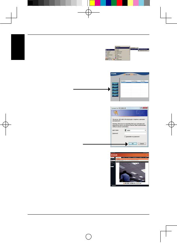
Click on the D-Link Setup Wizard SE icon that was created in your Windows Start menu.
Start > D-Link > Setup Wizard SE
The Setup Wizard will appear and display the MAC address and IP address of your camera(s). If you have a DHCP server on your network, a valid IP Address will be displayed. If your network does not use a DHCP server, the network camera's default static IP 192.168.0.20 will be displayed.
Click the Wizard button to continue.
Enter the Admin ID and password. When logging in for the first time, the default Admin ID is admin with the password left blank.
Click Next, to proceed to the next page.
Select DHCP if your camera obtains an IP address automatically when it boots up. Select static IP if the camera will use the same IP address each time it is started.
Click Next, to proceed to the next page.
Take a moment to confirm your settings and click Restart. 
D-Link DCS-6511 Quick Install Guide
ENGLISH
9
DCS-6511_A1_QIG_v1.00(EU).indd 9 |
2010/10/13 11:20:00 |
ENGLISH
Viewing Camera via Web Browser
Click on the D-Link Setup Wizard SE icon that was created in your Windows Start menu.
Start > D-Link > Setup Wizard SE
Select the camera and click the button labeled "Link" to access the web configuration.
The Setup Wizard will automatically open your web browser to the IP address of the camera.
Enter admin as the default username and leave the password blank. Click OK to continue.
This section shows your camera’s live video. You can select your video profile and view or operate the camera. For additional information about web
configuration, please refer to the user manual included on the CD-ROM or the D-Link website.
|
|
10 |
|
|
D-Link DCS-6511 Quick Install Guide |
||
|
|
|
|
|
|
|
|
|
|
|
|
|
|
|
|
|
|
|
|
|
|
|
|
|
|
|
|
|
|
|
|
|
|
|
|
|
|
|
|
DCS-6511_A1_QIG_v1.00(EU).indd 10 |
2010/10/13 11:20:01 |
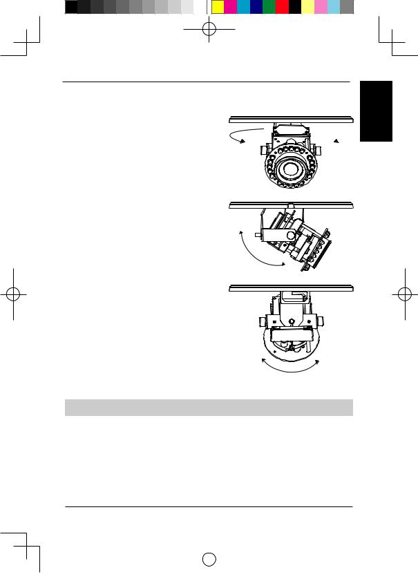
6. Adjusting the lens 3-axis angel
Adjus the Viewing Angle of the 3-axis Mechanism
Turn the lens module left and right until the desired position is achieved; tighten the pan screw once completed.
ENGLISH
Loosen the tilt screws on both sides of the camera, and turn the lens module up and down until the desired position is achieved; tighten the tilt screws once completed.
Turn the lens to adjust the IP camera’s image until the desired orientation is achieved, tighten the image adjustment screw once completed.
TECHNICAL SUPPORT
United Kingdom (Mon-Fri) website: http://www.dlink.co.uk FTP: ftp://ftp.dlink.co.uk Home Wireless/Broadband 0871 873 3000 (9.00am–06.00pm, Sat 10.00am-02.00pm) Managed, Smart, & Wireless Switches, or Firewalls 0871 873 0909 (09.00am05.30pm) (BT 10ppm, other carriers may vary.)
Ireland (Mon-Fri)
All Products 1890 886 899 (09.00am-06.00pm, Sat 10.00am-02.00pm)
Phone rates: €0.05ppm peak, €0.045ppm off peak times
D-Link DCS-6511 Quick Install Guide |
11 |
|
|
|
|||
|
|
|
|
|
|
|
|
|
|
|
|
|
|
|
|
|
|
|
|
|
|
|
|
|
|
|
|
|
|
|
|
|
|
|
|
|
|
|
|
DCS-6511_A1_QIG_v1.00(EU).indd 11 |
2010/10/13 11:20:01 |
NOTES
DCS-6511_A1_QIG_v1.00(EU).indd 12 |
2010/10/13 11:20:01 |

DCS-6511 Installationsanleitung
Diese Installationsanleitung bietet Ihnen grundlegende Anleitungen zur Installation der DCS-6511 Netzwerkkamera in Ihrem Netzwerk. Zusätzliche Informationen zur Verwendung der Kamera finden Sie im Benutzerhandbuch, das Ihnen auf der CD, die diesem Paket beiliegt, oder über die D-Link Support-Website zur Verfügung steht.
Installationsschritte
1.Prüfen Sie den Packungsinhalt, ob er mit den auf der Liste unten aufgeführten Artikeln übereinstimmt.
2.Hardware-Überblick
3.SD-Karteninstallation
4.Hardware-Installation
5.Konfiguration mithilfe des Assistenten
6.3-Achsenwinkel des Objektivs einstellen
1. Packungsinhalt
DCS-6511 Netzwerkkamera
CD-ROM mit Software und HandbuchSchnellinstallationsanleitung
Stromadapter/Netzteil
AV- & Stromkabel
SicherheitsschraubendreherCAT -5 Ethernet-Kabel
Adapter für ErweiterungKabelmantel
Befestigungsklammer und SchraubenGummistopfen
Sollte einer der oben aufgeführten Artikel fehlen, wenden Sie sich bitte an Ihren Fachhändler.
Sicherheitshinweis:
Installation und Wartungsarbeiten sollten nur von zertifizierten Technikern vorgenommen werden, zu jeder Zeit allen örtlich geltenden Richtlinien und Anforderungen entsprechen sowie verhindern, dass Ihr Garantieanspruch erlischt.
D-Link DCS-6511 Quick Install Guide
DEUTSCH
13
DCS-6511_A1_QIG_v1.00(EU).indd 13 |
2010/10/13 11:20:01 |
DEUTSCH
14
2. Hardware-Überblick
24 V Stromanschluss
Für den Anschluss an 24 V Wechselstrom
Stromanschluss
Für den Anschluss an 12 V Gleichstrom
Ethernet-Anschlussbuchse
RJ-45-Anschluss für Ethernet, der auch für die Stromzufuhr (PoE) der Kamera verwendet werden kann
Audio-Eingang |
DE/DA-Verkabelung, 12V |
|
Gleichstromausgang |
||
Für den Anschluss eines |
||
E/A-Anschlüsse für externe Geräte |
||
Mikrofons |
||
|
||
|
Audio-Ausgang |
|
|
Anschluss für |
|
|
Lautsprecher |
3. SD-Karteninstallation
Vorbereitende Demontage der Kamera
Öffnen Sie das Kameragehäuse, indem Sie die 4 Schrauben lösen. Nehmen Sie den Dom vom Sockel der Kamera.
Installation der SD-Karte
Stecken Sie die SD-Karte in die Kamera. Achten Sie darauf, dass die goldfarbenen Kontakte auf den Kamerafuß zeigen. Um die SD-Karte auszuwerfen, drücken Sie sie leicht in den Steckplatz.
D-Link DCS-6511 Quick Install Guide
DCS-6511_A1_QIG_v1.00(EU).indd 14 |
2010/10/13 11:20:02 |
4. Standardmontageanleitungen
Montage und Installation
Genaue Anleitungen zur Installation und Montage der Kamera mithilfe eines Befestigungsbügels finden Sie im Benutzerhandbuch.
Methode 1 – Verdeckte Kabelinstallation
Höhe: 23 mm
Durchmesser: 183 mmGewicht: 400 g
Abbildung 2.1
Abbildung 2.2
DEUTSCH
D-Link DCS-6511 Quick Install Guide |
15 |
|
|
|
|
|||
|
|
|
|
|
|
|
|
|
|
|
|
|
|
|
|
|
|
|
|
|
|
|
|
|
|
|
|
|
|
|
|
|
|
|
|
|
|
|
|
|
|
|
|
|
DCS-6511_A1_QIG_v1.00(EU).indd 15 |
2010/10/13 11:20:02 |

Methode 2 – Exponierte Kabelinstallation
Höhe: 23 mm
Durchmesser: 183 mmGewicht: 400 g
DEUTSCH
Abbildung 2.3 |
|
|
|
Abbildung 2.4 |
|
|
|
||
|
|
|
|
|
|
|
|
|
|
Abbildung 2.5 |
Abbildung 2.6 |
|
|
|
16 |
|
|
D-Link DCS-6511 Quick Install Guide |
||
|
|
|
|
|
|
|
|
|
|
|
|
|
|
|
|
|
|
|
|
|
|
|
|
|
|
|
|
|
|
|
|
|
|
|
|
|
|
|
|
|
|
|
|
|
DCS-6511_A1_QIG_v1.00(EU).indd 16 |
2010/10/13 11:20:03 |
Montage für hängende Kamera (DCS-34-2)
Höhe: 201 mm
Durchmesser: 150 mmGewicht: 665 g
Bügelkappe
Montageplatte
Abbildung 3.1
Gummidichtungsring
Deckenhalterung |
DEUTSCH |
|
Bügelkappe
Abbildung 3.2
Abbildung 3.3 |
Abbildung 3.4 |
D-Link DCS-6511 Quick Install Guide |
17 |
DCS-6511_A1_QIG_v1.00(EU).indd 17 |
2010/10/13 11:20:03 |

DEUTSCH
18
Montage für gebogene Kamerabügelhalterung (DCS-34-3)
Höhe: 253 mm
Durchmesser: 150 mmGewicht: 770 g
Bügelkappe
Gebogene
Bügelhalterung
Montageplatte
Abbildung 4.1 |
Bügelkappe |
Abbildung 4.2
Gebogene
Bügelhalterung
Dome-Kamera
Abbildung 4.3 |
Abbildung 4.4 |
D-Link DCS-6511 Quick Install Guide
DCS-6511_A1_QIG_v1.00(EU).indd 18 |
2010/10/13 11:20:03 |
 Loading...