


 Loading...
User Manual
Product Model: DAS-3626
VDSL2 Switch
Release 1.00
©Copyright 2009. All rights reserved

DGS-3700-12/DGS-3700-12G Series Layer 2 Gigabit Ethernet Switch User Manual
_________________________________________________________________________________
Information in this document is subject to change without notice. © 2009 D-Link Corporation. All rights reserved.
Reproduction in any manner whatsoever without the written permission of D-Link Corporation is strictly forbidden.
Trademarks used in this text: D-Link and the D-LINK logo are trademarks of D-Link Corporation; Microsoft and Windows are registered trademarks of Microsoft Corporation.
Other trademarks and trade names may be used in this document to refer to either the entities claiming the marks and names or their products. D-Link Corporation disclaims any proprietary interest in trademarks and trade names other than its own.
October 2009 P/N 651EV3726015G
ii

|
DAS-3626 VDSL2 Switch User Manual |
|
Table of Contents |
Web-based Switch Configuration.................................................................................................................................... |
6 |
System Configuration.................................................................................................................................................... |
14 |
Switch Configuration...................................................................................................................................................... |
26 |
VDSL Configuration....................................................................................................................................................... |
53 |
Multicasting.................................................................................................................................................................... |
59 |
Storm Control................................................................................................................................................................ |
74 |
QoS............................................................................................................................................................................... |
76 |
ACL............................................................................................................................................................................... |
84 |
VLAN........................................................................................................................................................................... |
103 |
Security........................................................................................................................................................................ |
109 |
CPE Management....................................................................................................................................................... |
122 |
Status.......................................................................................................................................................................... |
135 |
Maintenance................................................................................................................................................................ |
154 |
System Log Entries..................................................................................................................................................... |
163 |
Glossary...................................................................................................................................................................... |
174 |
Password Recovery Procedure................................................................................................................................... |
176 |
iii

DAS-3626 VDSL2 Switch User Manual
Preface
The DAS-3626 User Manual is divided into sections that describe the system installation and operating instructions. Section 2 through Section 13 corresponds to a menu folder in the web management interface presented in the same order they appear in the web interface.
Section 1, Introduction to Web-based Switch Management – Describes how to connect to and use the Webbased switch management feature on the switch.
Section 2, System Configuration – Details for configuring some of the basic functions of the switch including System Information, IP Settings, Interface Settings, IPv6 Neighbor Settings, User Accounts, SNTP Settings and System Log Configuration. The Quick Configuration section of the home page includes a few menus that are not accessable in the main menu folders; these menus are featured in this section as well.
Section 3, Switch Configuration – This section describes menus common to Layer 2 switching for configuration of MAC Address Aging, Port Mirroring, Ethernet Settings, Traffic Segmentation, Forwarding Database configuration, CLI Paging, Port Mirroring, Port Trunks, LACP Port configuration, Loopback Detection setting, GVRP, DHCP Relay and Spanning Tree Protocol/Multiple Spanning Tree and CFM settings.
Section 4, VDSL Configuration – Settings for configuration of VDSL Profiles, VDSL Ports and various VDSL Status display menus are located here.
Section 5, Multicasting – Configuration menus for IGMP Snooping, Multicast Profile, Limited Range, Group settings and Multicast Listener Discovery (MLD) configuration.
Section 6, Storm Control – Configuration menus for multicast and broadcast storm control.
Section 7, QoS – Information for Quality of Service configuration. Menus include Bandwidth Control, 802.1P Default Priority, 802.1P User Priority, QoS Scheduling Mechanism, QoS Scheduling and In Band Manage Settings.
Section 8, ACL Configuration – Menus for configuration of ACL including the ACL Configuration Wizard, Access Profile List and ACL Finder.
Section 9, VLAN – Information for configuration of 802.1Q VLANs, 802.1v Protocol VLAN configuration.
Section 10, Security – Features information on security functions, including Safeguard Engine, Trusted Host, Port Security , MAC Spoofing Access, SSL setting, SSH setting and Access Authentication Control settings.
Section 11, CPE Management – Menus for configuration, upgrade and testing of remote CPE equipment and client LAN settings.
Section 12, Status – Features information about the monitoring switch and network functions including CPU Utilization, Port Utilization, Packet Size, Memory Utilization, Packets, Errors, System Log, Ping Test, VDSL monitoring and system Firmware Information.
Section 13, Maintenance – Menus for Firmware Upgrade, Configuration File Backup and restore, as well as the SNMP Settings menu folder are also located in the Maintenance folder.
Appendix A, System Log Entries – This table lists all the possible entries and their corresponding meanings that will appear in the System Log of this switch.
Appendix B, Glossary – Lists definitions for terms and acronyms used in this document.
Appendix C, Password Recovery Procedure - This section describes the procedure for resetting passwords on D-Link switches.
iv
DAS-3626 VDSL2 Switch User Manual
Intended Readers
The DAS-3626 User Manual Manual contains information for setup and management of the switch. This manual is intended for network managers familiar with network management concepts and terminology.
Typographical Conventions
|
Convention |
|
Description |
|
|
|
|
|
|
[ ] |
|
In a command line, square brackets indicate an optional entry. For example: [copy |
|
|
|
|
|
filename] means that optionally you can type copy followed by the name of the file. Do not |
|
|
|
|
type the brackets. |
|
|
|
|
|
|
Bold font |
|
Indicates a button, a toolbar icon, menu, or menu item. For example: Open the File menu |
|
|
|
|
|
and choose Cancel. Used for emphasis. May also indicate system messages or prompts |
|
|
|
|
appearing on your screen. For example: You have mail. Bold font is also used to |
|
|
|
|
represent filenames, program names and commands. For example: use the copy |
|
|
|
|
command. |
|
|
|
|
|
|
Boldface |
Typewriter |
Indicates commands and responses to prompts that must be typed exactly as printed in |
|
|
Font |
|
the manual. |
|
|
|
|
|
|
|
Initial capital letter |
Indicates a window name. Names of keys on the keyboard have initial capitals. For |
|
||
|
|
|
example: Click Enter. |
|
|
|
|
|
|
Italics |
|
Indicates a window name or a field. Also can indicate a variables or parameter that is |
|
|
|
|
|
replaced with an appropriate word or string. For example: type filename means that you |
|
|
|
|
should type the actual filename instead of the word shown in italic. |
|
|
|
|
|
|
Menu Name > Menu |
Menu Name > Menu Option Indicates the menu structure. Device > Port > Port |
|
||
Option |
|
Properties means the Port Properties menu option under the Port menu option that is |
|
|
|
|
|
located under the Device menu. |
|
|
|
|
|
|
Notes, Notices, and Cautions
A NOTE indicates important information that helps you make better use of your device.
A NOTICE indicates either potential damage to hardware or loss of data and tells you how to avoid the problem.
A CAUTION indicates a potential for property damage, personal injury, or death.
5
DAS-3626 VDSL2 Switch User Manual
Section 1
Web-based Switch Configuration
Introduction
Out-of-Band Access to System Management
Interface IP Settings for Switch Management
Login to Web Manager
Web-based User Interface
Web Pages
Introduction
All software functions of the switch can be managed, configured and monitored via the embedded web-based (HTML) interface. The switch can be managed from remote stations anywhere on the network through a standard browser such as Microsoft Internet Explorer.
The web-based management module and command line interface (console program or Telnet) are different ways to access the same internal switching software and configure it. Thus, all settings encountered in web-based management are the same as those found in the command line interface (CLI).
Out-of-Band Access to System Management
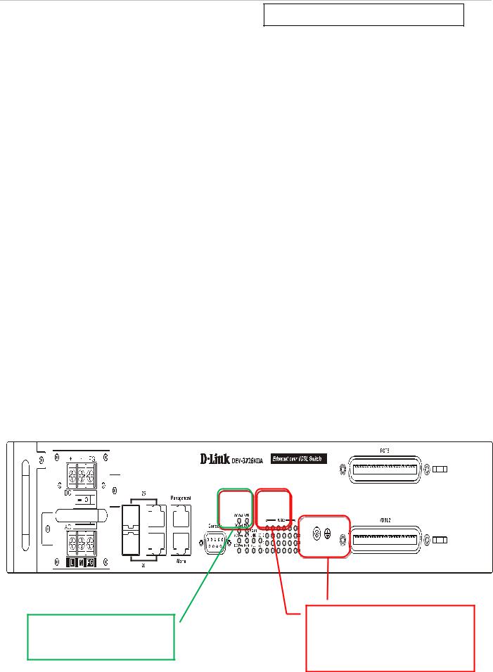
Management access to the System can be done out-of-band with a physical connection directly to the switch. Connect to the RS-232 Console serial port on the front panel, or use the Mangament Ethernet port located next to the Console port. Use standard terminal emulation software for Console port access as described in the CLI Command Reference Manual. Use of the Management port provides the options of using either the web-based management module or the command line interface via Telnet. The Management port must reside on a different subnet than the inband System interface. The default IP settings for the Management port are 192.168.1.10/255.255.255.0 while the default IP settings for the in-band network interface are 10.90.90.90/255.0.0.0. See below for instructions on how to change the IP settings for the in-band and out-of-band interfaces used for switch management. For more information about physical ports and other hardware information please see the Hardware Manual.
Use either Gigabit Ethernet port (ports 25 and 26) for in-band access.
Use the Management Ethernet port (default IP address 192.168.1.10) or the Console (RS-232) port for out- of-band access.
Figure 1. Front panel in-band and out-of-band ports
6
DAS-3626 VDSL2 Switch User Manual
Interface IP Settings for Switch Management
The switch maintains two IP interfaces used for management, one in-band IP interface named System, and one out- of-band IP interface named outband. These IP interfaces cannot reside within the same subnet. If the outband interface is configured with IP settings that place it within the same subnet as the System IP interface, the IP interface for outband is invalidated.
The default IP settings of the in-band IP interface System are 10.90.90.90/255.0.0.0. The default IP settings for the ou-of-band IP interface outband are 192.168.1.10/255.255.255.0. The CLI command syntax used to change the IP settings of the in-band IP interface is config ipif System ipaddress xxx.xxx.xxx.xxx/yyy.yyy.yyy.yyy where the x’s represent the IP address to be assigned to the IP interface named System and the y’s represent the corresponding subnet mask. The CLI command syntax used to change the IP settings of the out-of-band IP interface is config ipif outband ipaddress xxx.xxx.xxx.xxx/yyy.yyy.yyy.yyy. Alternatively you can use CIDR notation for the IP settings, xxx.xxx.xxx.xxx/z, where the x’s represents the corresponding number of subnets.
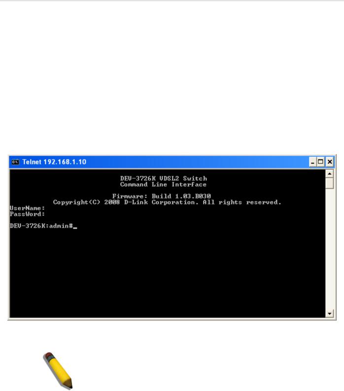
Connection to the switch using Telnet can be done by connecting to the Management Ethernet port and launching the Windows Command Prompt or similar software. Make sure your computer’s IP settings allow connection to the switch default IP subnet of the outband interface (192.168.1.0) and Telnet to 192.168.1.10. You will be prompted for a User Name and Password, there is no default user name or password, simply press the Enter at each prompt to obtain the administrator’s prompt DAS-3626:admin# as seen in the example below. The switch is not ready for configuration.
Figure 2. Menus Command Prompt using out-of-band Telnet connection
NOTE: Telnet can also be used in-band by connecting through port 25 or 26. The Factory default IP address of the in-band interface “System” is 10.90.90.90.
7
DAS-3626 VDSL2 Switch User Manual
Login to Web Manager
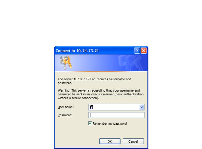
To use the web-based management module for switch management, run the browser you have installed on your computer and point it to the IP address you have defined for the device. The URL in the address bar should read something like: http://123.123.123.123, where the numbers 123 represent the IP address of the switch; this opens the management module's user authentication window, as seen below.
Figure 3. Enter Network Password dialog
There is no default user name or password. At the User Name and Password fields, click on OK. This opens the webbased management interface. Switch management features available in the web-based manager are explained below.
8
DAS-3626 VDSL2 Switch User Manual
Web-based User Interface
The user interface provides access to various switch configuration and management windows, allows you to view performance statistics, and permits you to graphically monitor the system status.
Areas of the User Interface
The figure below shows the user interface. The user interface is divided into three distinct areas as described in the table.
Area 2
Area 1
Save and back up configuration settings, reboot, reset configuration and download firmware drop-down menus.
|
Figure 4. Main Web-Manager page |
|
|
Area |
Function |
|
|
Area 1 |
Select the folder or window to be displayed. The folder icons can be opened to display the hyper- |
|
linked window buttons and subfolders contained within them. Click the D-Link logo to go to the D- |
|
Link website. |
|
|
Area 2 |
Presents a graphical near real-time image of the front panel of the switch. This area displays the |
|
switch's ports and expansion modules showing port activity. |
|
Various areas of the graphic can be selected for performing management functions, including port |
|
configuration. |
|
|
Area 3 |
Presents switch information based on your selection and the entry of configuration data. |
|
|
Area 4 |
Links to configuration menus, some of which are not accessable in the configuration menu folders |
|
(displayed in Area 1) are located here. |
|
|
|
NOTICE: Any changes made to the switch configuration during the |
|
current session must be saved using the drop-down Save menu or use |
|
the command line interface (CLI) command save. |
9

DAS-3626 VDSL2 Switch User Manual
System Save Menus
The web interface for the switch includes two drop-down menus, the Save and Tools menus, located just above the menu folders. The Save menu includes options to save switch configuration settings and switch log.
Figure 5. Save Configuration drop-down menu
To save the current configuration, from the Save drop-down menu, pull the cursor down to the Save Configuration option. The Save Configuration menu display appears during the saving process. Upon successfully saving the configuration, a message informs you the save is completed.
Figure 6. Save Configuration display
In addition to the Save Configuration option, the Save menus offer a Save Log and Save All option. The Save All option saves both the System Log and the current configuration file.
10
DAS-3626 VDSL2 Switch User Manual
System Tools Menus
The Tools drop-down menu includes links Configuration File Backup & Restore, Upload Log File, Reset, Download Firmware and Reboot System menus.
Figure 7. Tools drop-down menu
These menus are described below.
Configuration File Backup & Restore
The switch supports dual image storage for configuration file backup and restoration. The firmware and configuration images are indexed by ID number 1 or 2. To change the boot firmware image, use the Configuration ID drop-down menu to select the desired configuration file to backup or restore. The default switch settings will use image ID 1 as the boot configuration or firmware.
To backup the configuration file, enter the Server IP (either IPv4 or IPv6), interface name, file/path name, desired Configuration ID, and click Backup.
To restore the configuration file, enter the Server IP (either IPv4 or IPv6), interface name, file/path name, desired Configuration ID, and click Restore.
Figure 8. Configuration File Backup & Restore menu
Upload Log File
A history and attack log can be uploaded from the switch to a TFTP server. To upload a log file, enter a Server IP address, Interface Name and file/path name and then click Upload or Upload Attack Log.
Figure 9. Upload Log File menu
11
DAS-3626 VDSL2 Switch User Manual
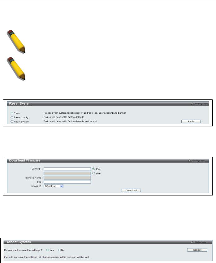
Reset
The Reset function has several options when resetting the switch. Some of the current configuration parameters can be retained while resetting all other configuration parameters to their factory defaults.
NOTE: Only the Reset System option will enter the factory default parameters into the switch's non-volatile RAM, and then restart the switch. All other options enter the factory defaults into the current configuration, but do not save this configuration. Reset System will return the switch's configuration to the state it was when it left the factory
NOTE: The serial port’s baud rate will not be changed by the reset command. It will not be restored to the factory default setting.
Reset gives the option of retaining the switch's User Accounts and History Log while resetting all other configuration parameters to their factory defaults. If the switch is reset using this window, and Save Changes is not executed, the switch will return to the last saved configuration when rebooted.
Figure 10. Reset System menu
Download Firmware
The following window is used to download firmware for the switch.
Figure 11. Download Firmware menu
Enter the Server IP address, the Interface Name, the path/file name and select the desired Image ID. Click Download to initiate the file transfer.
Reboot System
The following window is used to restart the switch.
Figure 12. Reboot System menu
Clicking the Yes radio button will instruct the switch to save the current configuration to non-volatile RAM before restarting the switch.
Clicking the No radio button instructs the switch not to save the current configuration before restarting the switch. All of the configuration information entered from the last time Save Changes was executed will be lost.
Click the Reboot button to restart the switch.
12
DAS-3626 VDSL2 Switch User Manual
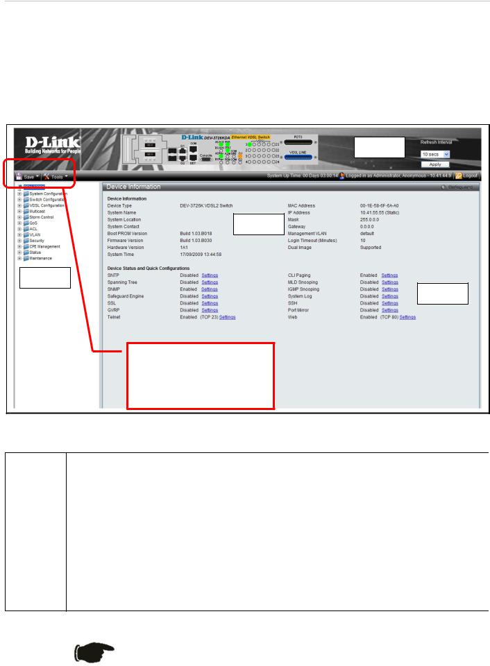
Device Information and Quick Configuration Links
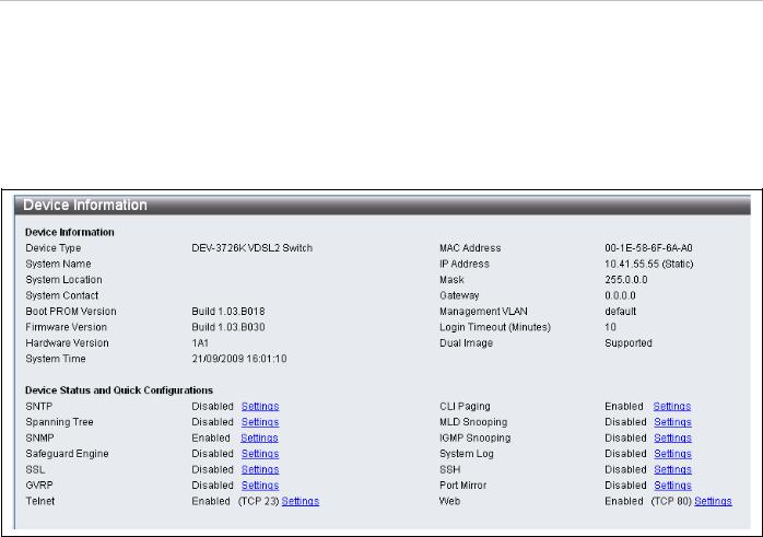
This window contains the main settings for all major functions on the switch and appears automatically when you log on. To return to the Device Information and Quick Configuration likns, click the DAS-3626 device name above the menu folders. The Device Information display shows the switch’s MAC Address (assigned by the factory and unchangeable), the Boot PROM Version, Firmware Version and Hardware Version as well as other information about different settings on the switch. This information is helpful to keep track of PROM and firmware updates and to obtain the switch's MAC address for entry into another network device's address table, if necessary. In addition, this window displays the status of functions on the switch to quickly assess their current global status. Some functions are hyper-linked to their configuration window for easy access from the Device Information window.
Figure 13. Device Information display and Quick Configuration links
13

DAS-3626 VDSL2 Switch User Manual
Section 2
System Configuration
System Information
IP Settings
IPv6 Neighbor Settings
Serial Port Settings
Web Settings
Telnet Setting
Time Setting
TimeZone Setting
Users Setting
System Log Setting
System Log Server
Configuration menus in the System Configuration folder are used to change general system settings sucha as IP settings for the two switch IP interfaces, system time settings and user account settings.This section describes the menus contained in the System Configuration menu directory.
14
DAS-3626 VDSL2 Switch User Manual
System Information
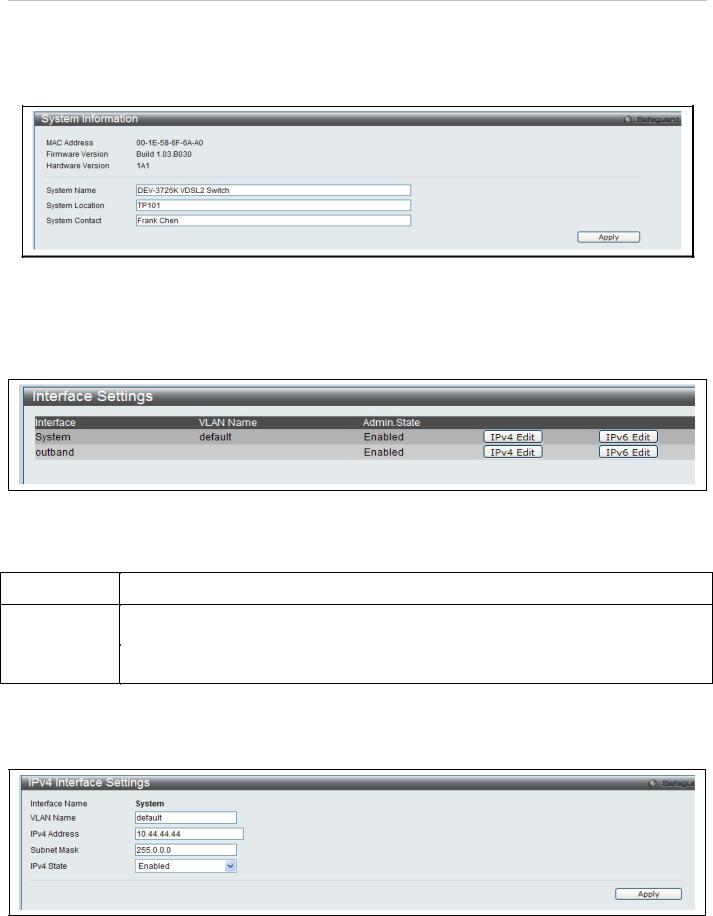
Use the System Information menu to add name, location and administrator contact information. To view the menu, click System Configuration > System Information as shown below:
Figure 14. System Information menu
Interface Settings
The Interface Settings menu is used to access the IP settings for the two IP interefaces of the switch. To view the menu, click System Configuration > IP Settings as shown below:
|
|
Figure 15. Interface Settings menu |
|
|
The parameter values below are displayed in the Interface Settings menu: |
|
|
|
|
|
|
|
Parameter |
Description |
|
|
|
|
|
Interface |
The name of the IP interfaces used to manage the switch. |
|
|
|
|
|
|
VLAN Name |
The name of the VLAN that includes the System interface. This can be configured in the IPv4 or |
|
|
IPv6 Interface Settings menu for the interface. |
|
||
|
|
|
|
Admin. State |
Displays the current state of the interface. Access the IPv4 or IPv6 Interface Settings menu to |
|
|
enable or disable the interface. |
|
||
|
|
|
|
To change the IP settings, VLAN Name, or Admin.State, click on the IPv4 Edit or IPv6 Edit button for the interface to be configured.
In the new menu, enter the new VLAN Name, IPv4 Address and Subnet Mask, select the IPv4 State and click Apply. To edit an entry for IPv4 features click the corresponding IPv4 Edit button.
Figure 16. IPv4 Interface Settings Edit menu
15
DAS-3626 VDSL2 Switch User Manual
The following parameters can be configured:
|
Parameter |
Description |
|
|
|
|
|
Interface Name |
Displays the interface being edited. |
|
|
VLAN Name |
Enter the name of the VLAN corresponding to the interface. (System interface only) |
|
|
|
|
Enter an alternative IPv4 address. Currently an interface can only have one IPv4 address defined. |
|
IPv4 Address |
Therefore multinetting configuration of IPv4 must be done through creation of a secondary |
|
|
interface on the same VLAN, instead of directly configuring multiple IPv4 addresses on the same |
|
||
|
|
|
|
|
|
interface. |
|
Subnet Mask |
Enter the corresponding subnet mask. |
|
|
IPv4 State |
This function allows user to enable the IPv4 address on the IP interface. |
|
|
Click Apply to implement changes made.
To edit an entry for IPv6 features click the corresponding IPv6 Edit button.
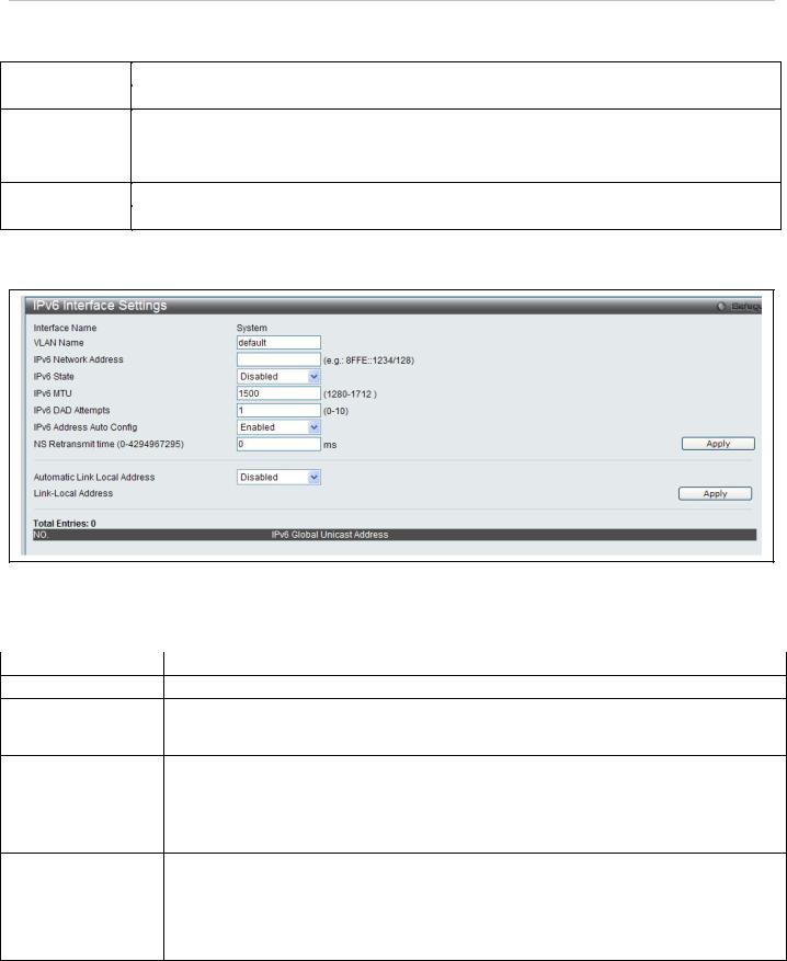
Figure 17. IPv6 Interface Settings Edit menu
The following parameters can be configured:
|
Parameter |
Description |
|
|
|
|
|
Interface Name |
Displays the interface being edited. |
|
|
VLAN Name |
Enter the name of the VLAN corresponding to the interface. (System interface only) |
|
|
IPv6 Network |
Enter the IPv6 Network Address to be configured. The interface can have multiple IPv6 |
|
|
addresses defined. Configuration of IPv6 addresses must be done through the command |
|
||
Address |
|
||
config ipif. |
|
||
|
|
|
|
IPv6 State |
Allows the user to enable or disable the IPv6 state on the interface. |
|
|
NS Retransmit time |
This field is used to set the interval, in milliseconds that the switch will produce neighbor |
|
|
solicitation packets to be sent out over the local network. This is used to discover IPv6 |
|
||
(0-4294967295) |
neighbors on the local network. The user may select a time between 0 and 4294967295 |
|
|
|
|
milliseconds. The default is 0. |
|
|
|
Enables or disables the automatic configuration of link local addresses when there are no |
|
Automatic Link |
IPv6 addresses explicitly configured. When an IPv6 address is explicitly configured, the link |
|
|
local address will be automatically configured, and the IPv6 processing will be started. When |
|
||
Local Address |
there is no IPv6 address explicitly configured, by default, link local address is not configured |
|
|
|
|
and the IPv6 processing will be disabled. By enabling this automatic configuration, the link |
|
|
|
local address will be automatically configured and IPv6 processing will be started. |
|
Click Apply to implement changes made.
16
DAS-3626 VDSL2 Switch User Manual
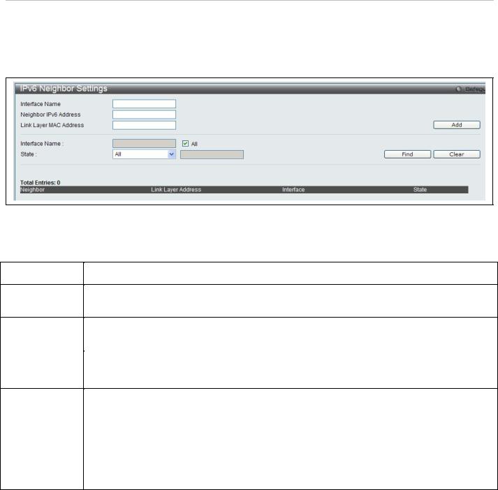
IPv6 Neighbor Settings
This window allows the user to create and configure IPv6 Neighbor settings on the switch. The switch’s current IPv6 neighbor settings will be displayed in the table at the bottom of this window.
To view this window, click System Configuration > IPv6 Neighbor Settings as shown below:
Figure 18. IPv6 Neighbor Settings menu
The following parameters can be configured:
|
Parameter |
Description |
|
|
|
|
|
Interface Name |
Enter the interface name of the IPv6 neighbor you wish to configure. |
|
|
|
|
|
|
Neighbor IPv6 |
Enter the neighbor IPv6 address of the entry you wish to configure. |
|
|
Address |
|
|
|
|
|
|
|
Link Layer MAC |
Enter the MAC address of the neighbor device to be added as an IPv6 neighbor on the IP |
|
|
Address |
interface. |
|
|
|
|
|
|
Interface Name |
In order to search for a previously configured Interface name enter the appropriate information |
|
|
|
|
and click Find. To remove a previously configured Interface enter the Interface name and click |
|
|
|
Clear. |
|
State |
To find or delete specific entries use the pull down menu to select All, Address, Static, or |
|
|
|
|
Dynamic. |
|
|
|
All – Select All to view all configured neighbor devices which are IPv6 neighbors of the IP |
|
|
|
interface previously created. |
|
|
|
Address – Select Address and enter the IPv6 address of the entry you wish to find. |
|
|
|
Static – Select Static to view all statically entered IPv6 neighbors on the switch. |
|
|
|
Dynamic – Select Dynamic to view all dynamically configured neighbor devices which are IPv6 |
|
|
|
neighbors of the IP interface previously created. |
|
Click Add to add a new entry, click Find to search for a specific entry or click Clear to remove an entry.
17
DAS-3626 VDSL2 Switch User Manual
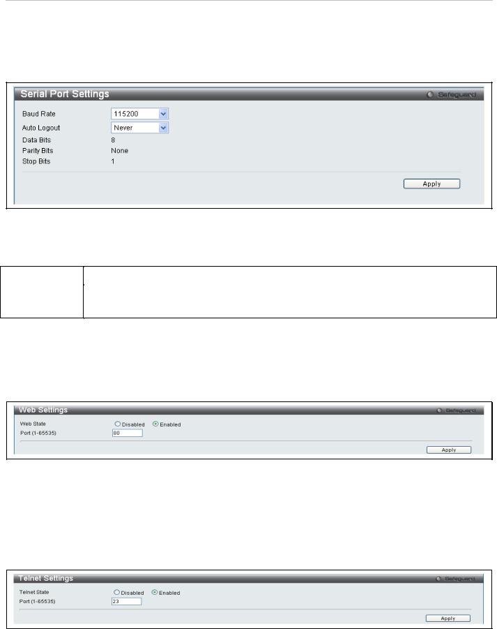
Serial Port Setting
Use the Serial Port Setting window to console serial port setting, config Baud Rate and Auto Logout setting. To view this window, click System Configuration > Serial Port Settings as shown below:
Figure 19. Serial Port Settings
The following fields can be set:
|
Parameter |
Description |
|
|
|
|
|
Baud Rate |
Select the baud rate used for the console serial port. |
|
|
|
|
|
|
Auto Logout |
To configure console logout time, choose 2, 5, 10, 15 minutes or never logout from the pull-down |
|
|
|
|
menu. |
|
|
|
|
|
Web Settings
Web-based management is Enabled by default. If you choose to disable this by selecting Disabled, you will lose the ability to configure the system through the web interface as soon as these settings are applied.
To view this menu, click the Web Settings link in the Quick Configuration menu as shown below:
Figure 20. Web Settings menu
Telnet Settings
Telnet configuration is Enabled by default. If you do not want to allow configuration of the system through Telnet choose Disabled. The TCP ports are numbered between 1 and 65535. The "well-known" TCP port for the Telnet protocol is 23.
To view this menu, click the Telnet Settings link in the Quick Configuration menu as shown below:
Figure 21. Telnet Settings menu
18
DAS-3626 VDSL2 Switch User Manual
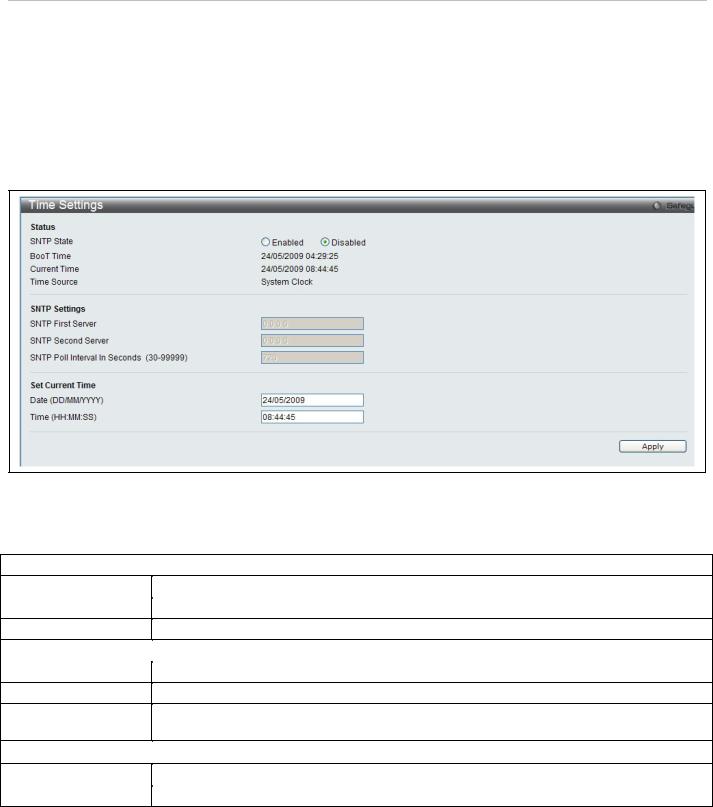
System Time and SNTP Settings
Simple Network Time Protocol Settings used to set system time are configured in two menus, the Time Settings and Time Zone Settings menus.
Time Settings
This window is used to configure the time settings for the switch.
To view this window, click System Configuration > Time Settings (alternatively this menu is also displayed by clicking the SNTP Settings link in the Quick Configuration menu in the Device Information page) as shown below:
Figure 22. Time Settings menu
The following parameters can be set or are displayed:
|
Parameter |
Description |
|
|
|
|
|
|
|
Status |
|
SNTP State |
Use the radius button to select an Enabled or Disabled SNTP state. |
|
|
Current Time |
Displays the Current Time set on the switch. |
|
|
Time Source |
Displays the time source for the system. |
|
|
|
|
SNTP Settings |
|
SNTP First Server |
This is the IP address of the primary server the SNTP information will be taken from. |
|
|
SNTP Second Server |
This is the IP address of the secondary server the SNTP information will be taken from. |
|
|
SNTP Poll Interval in |
This is the interval, in seconds, between requests for updated SNTP information. |
|
|
Seconds (30-99999) |
|
|
|
|
|
Set Current Time |
|
Date (DD/MM/YYYY) |
Enter the current date in day, month and year to update the system clock. |
|
|
Time in (HH:MM:SS) |
Enter the current time in hours, minutes, and seconds. |
|
|
Click Apply to implement changes made.
19
DAS-3626 VDSL2 Switch User Manual
Time Zone Settings
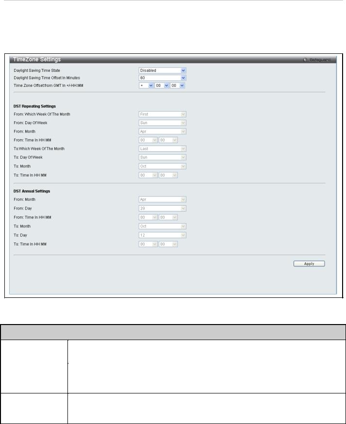
The following window is used to configure time zones and Daylight Savings time settings for SNTP. To view this window, click System Configuration > TimeZone Settings as shown below:
Figure 23. Time Zone and DST Settings menu
The following parameters can be set:
Time Zone and DST
Daylight Saving |
Use this pull-down menu to enable or disable the DST Settings. |
|
Time State |
||
|
||
|
|
|
Daylight Saving |
Use this pull-down menu to specify the amount of time that will constitute your local DST offset |
|
Time Offset in |
||
30, 60, 90, or 120 minutes. |
||
Minutes |
||
|
||
|
|
|
Time Zone Offset |
Use these pull-down menus to specify your local time zone's offset from Greenwich Mean |
|
from GMT in +/- |
||
Time (GMT.) |
||
HH:MM |
||
|
||
|
|
20
DAS-3626 VDSL2 Switch User Manual
DST Repeating Settings
Using repeating mode will enable DST seasonal time adjustment. Repeating mode requires that the DST beginning and ending date be specified using a formula. For example, specify to begin DST on Saturday during the second week of April and end DST on Sunday during the last week of October.
From :Which Week |
Enter the week of the month that DST will start. |
of the Month |
|
|
|
From: Day of the |
Enter the day of the week that DST will start on. |
Week |
|
|
|
From: Month |
Enter the month DST will start on. |
|
|
From: Time in |
Enter the time of day that DST will start on. |
HH:MM |
|
|
|
To: Which Week of |
Enter the week of the month the DST will end. |
the Month |
|
|
|
To: Day of the |
Enter the day of the week that DST will end. |
Week |
|
|
|
To: Month |
Enter the month that DST will end. |
|
|
To:Time in HH:MM |
Enter the time DST will end. |
|
|
DST Annual Settings
Using annual mode will enable DST seasonal time adjustment. Annual mode requires that the DST beginning and ending date be specified concisely. For example, specify to begin DST on April 3 and end DST on October 14.
From: Month |
Enter the month DST will start on, each year. |
|
|
From: Day |
Enter the day of the week DST will start on, each year. |
|
|
From: Time in |
Enter the time of day DST will start on, each year. |
HH:MM |
|
|
|
To: Month |
Enter the month DST will end on, each year. |
|
|
To: Day |
Enter the date DST will end on, each year. |
|
|
To: Time in HH:MM |
Enter the time of day that DST will end on, each year. |
|
|
Click Apply to implement changes made to the Time Zone and DST window.
21
DAS-3626 VDSL2 Switch User Manual
User Account Settings
The User Accounts menu is used to control user privileges, create new users and view existing User Accounts. To view the menu, click System Configuration > User Settings:
Figure 24. User Accounts menu
The following fields can be set:
|
Parameter |
Description |
|
|
|
|
|
User Name |
The name of the user, an alphanumeric string of up to 15 characters. |
|
|
|
|
|
|
Access Right |
There are three levels of user privileges, Admin, Operator and User. Some menu selections |
|
|
|
|
available to users with Admin privileges may not be available to those with User or Operator |
|
|
|
level privileges. |
|
|
|
There are 3 levels of security offered on the switch, the Operator level privilege will allow users to |
|
|
|
configure and view configurations on the switch, except for those involving security features, |
|
|
|
which are still left to the Admin level privilege. Operator level users can be authenticated through |
|
|
|
either the local authentication method of the switch, or through the Access Authentication Control |
|
|
|
feature, discussed later in this document. Once the user has logged in to the switch in the |
|
|
|
Operator level, certain security screens and windows will not be made available to view, or to |
|
|
|
configure. Only Admin level users have access to these features. |
|
|
|
(Ошибка: источник перекрестной ссылки не найден below summarizes Admin, Operator and |
|
|
|
User level privileges) |
|
|
|
|
|
New Password |
Enter a password for the new user. |
|
|
|
|
|
|
Confirm New |
Retype the new password. |
|
|
Password |
|
|
|
|
|
|
|
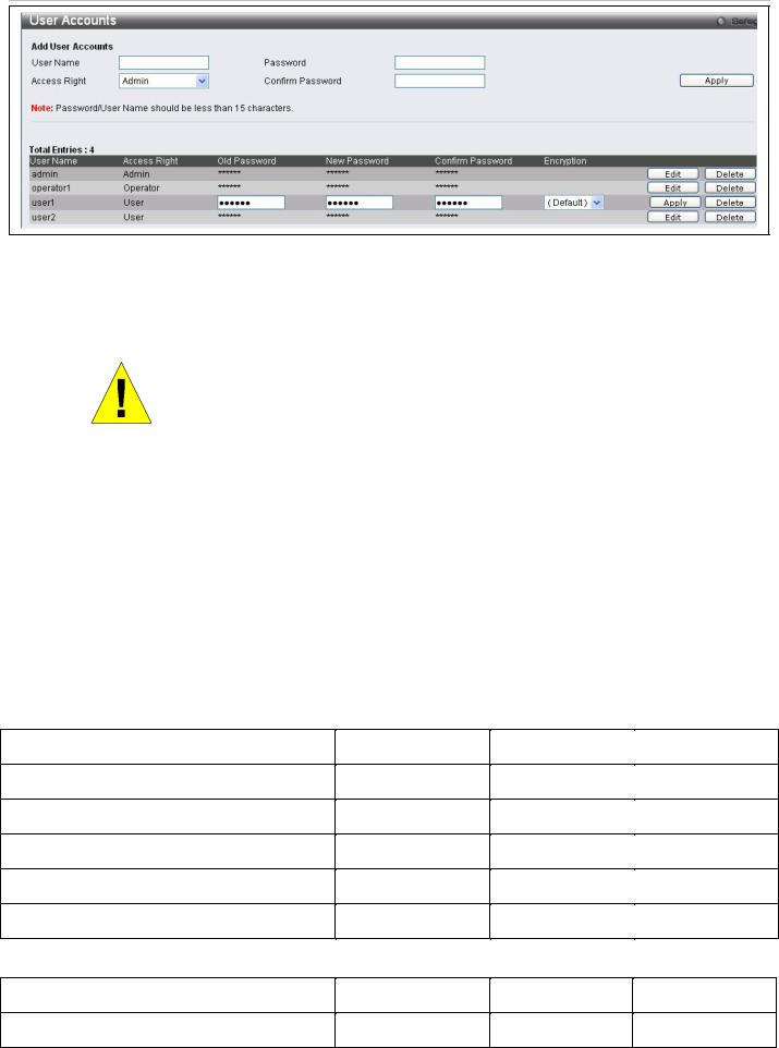
To add a new user, enter the appropriate information and click Apply. To delete an account click the corresponding Delete button. To modify an existing user account, click Edit as shown below.
22
DAS-3626 VDSL2 Switch User Manual
Figure 25. User Accounts menu
Enter the Old Password for the account, the New Password you wish to use, and retype the new password in the Confirm Password field. Use the drop-down menu to select the type of encryption (Default, Plain Text or Sha 1), and click Apply.
NOTICE: In case of lost passwords or password corruption, please refer to the D-Link website and the White Paper entitled “Password Recovery Procedure”, which will guide you through the steps necessary to resolve this issue.
Admin, Operator and User Privileges
Recently added to the levels of security offered on the switch, the Operator level privilege will allow users to configure and view configurations on the switch, except for those involving security features, which are still left to the Admin privilege. Operator users can be authenticated through either the local authentication method of the switch, or through the Access Authentication Control feature, discussed later in this document. Once the user has logged in to the switch in the Operator level, certain security screens and windows will not be made available to view, or to configure. Only Admin level users have access to these features.
There are three levels of user privileges, Admin, Operator and User. Some menu selections available to users with Admin privileges may not be available to those with User or Operator privileges.
The following table summarizes the Admin, Operator and User privileges:
|
Management |
Admin |
Operator |
User |
|
|
|
|
|
|
|
Configuration |
Yes |
Yes |
Read-only |
|
|
|
|
|
|
|
|
Network Monitoring |
Yes |
Yes |
Read-only |
|
|
|
|
|
|
|
|
Community Strings and Trap Stations |
Yes |
Yes |
Read-only |
|
|
|
|
|
|
|
|
Update Firmware and Configuration Files |
Yes |
No |
No |
|
|
|
|
|
|
|
|
System Utilities |
Yes |
Yes |
No |
|
|
|
|
|
|
|
|
Factory Reset |
Yes |
No |
No |
|
|
|
|
|
|
|
|
|
|
|
|
|
|
|
User Account Management |
|
|
|
|
|
|
|
|
|
|
Add/Update/Delete User Accounts |
Yes |
No |
No |
|
|
|
|
|
|
|
|
View User Accounts |
Yes |
No |
No |
|
|
|
|
|
|
|
|
|
Figure 26. Admin, Operator and User Privileges |
|
|
||
23
DAS-3626 VDSL2 Switch User Manual
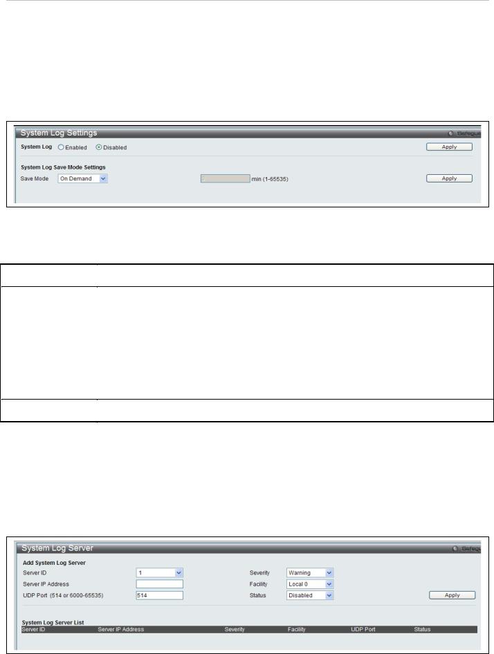
System Log Configuration
This section contains information for configuring various attributes and properties for System Log Configurations, including System Log Settings and System Log Host.
System Log Settings
This window allows the user to enable or disable the System Log and specify the System Log Save Mode Settings. To view this window, click System Configuration > System Log Settings as shown below:
|
|
Figure 27. System Log Settings menu |
|
|
The following parameters can be set: |
|
|
|
|
|
|
|
Parameter |
Description |
|
|
|
|
|
System Log |
To activate the System Log select Enabled or Disabled. |
|
|
|
|
|
|
Save Mode |
Use this drop-down menu to specify the method that will trigger a log entry. You can choose |
|
|
|
|
between On Demand, Time Interval and Log Trigger. |
|
|
|
On Demand – This method will only save log files when they manually tell the switch to do so, |
|
|
|
using the Save Log link in the Save folder. |
|
|
|
Time Interval – This method configures a time interval by which the switch will save the log |
|
|
|
files. The user may set a time between 1 and 65535 minutes. |
|
|
|
Log Trigger – This method will save log files to the switch every time a log event occurs on the |
|
|
|
switch. |
|
|
|
|
|
Minutes (1-65535) |
Enter a time interval, in minutes, for which you would like a log entry to be made. |
|
|
|
|
|
|
|
|
|
|
To add a new entry, enter the appropriate information and click Apply.
System Log Server
The switch can send Syslog messages to up to four designated servers using the System Log Server.
To view this window, click System Configuration > System Log Configuration > System Log Server as shown below:
Figure 28. System Log Server menu
24
DAS-3626 VDSL2 Switch User Manual
The following parameters can be set:
Parameter Description
Server ID |
Syslog server settings index (1-4). |
|
|
|
|
|
|
|
|
|
|
Server IP Address |
The IP address of the Syslog server. |
|
|
|
|
|
|
|
|||
UDP Port |
Type the UDP port number used for sending Syslog messages. The default is 514. |
||||
(514 or 6000-65535) |
|
|
|
|
|
|
|
|
|||
Severity |
This drop-down menu allows you to select the level of messages that will be sent. The options |
||||
|
are Warning, Informational, and All. |
|
|
|
|
|
|
|
|||
Facility |
Some of the operating system daemons and processes have been assigned Facility values. |
||||
|
Processes and daemons that have not been explicitly assigned a Facility may use any of the |
||||
|
"local use" facilities or they may use the "user-level" Facility. Those Facilities that have been |
||||
|
designated are shown in the following: Bold font indicates the facility values that the switch is |
||||
|
currently employing. |
|
|
|
|
|
Numerical |
Facility Code |
Numerical |
Facility Code |
|
|
0 |
kernel messages |
12 |
NTP subsystem |
|
|
1 |
user-level messages |
13 |
log audit |
|
|
2 |
mail system |
14 |
log alert |
|
|
3 |
system daemons |
15 |
clock daemon |
|
|
4 |
security/authorization messages |
16 |
local use 0 |
(local0) |
|
5 |
messages generated internally by |
17 |
local use 1 |
(local1) |
|
|
syslog line printer subsystem |
18 |
local use 2 |
(local2) |
|
7 |
network news subsystem |
19 |
local use 3 |
(local3) |
|
8 |
UUCP subsystem |
20 |
local use 4 |
(local4) |
|
9 |
clock daemon |
21 |
local use 5 |
(local5) |
|
10 |
security/authorization messages |
22 |
local use 6 |
(local6) |
|
11 |
FTP daemon |
23 |
local use 7 |
(local7) |
|
|
|
|
|
|
Status |
Choose Enabled or Disabled to activate or deactivate. |
|
|
||
|
|
|
|
|
|
|
|
|
|
|
|
25

DAS-3626 VDSL2 Switch User Manual
Section 3
Switch Configuration
MAC Address Aging Time
Ethernet Settings
FDB
Traffic Segmentation
CLI Paging
Port Mirror
LACP Port Settings
Loopback Detection Settings
QinQ Settings
GVRP
DHCP/BOOTP Relay Settings
Spanning Tree Settings
Multiple Spanning Tree Settings
CFM
The Switch Configurtion Section includes these functions discussed in detail.
26
DAS-3626 VDSL2 Switch User Manual
MAC Address Aging Time
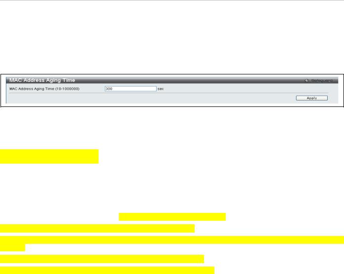
This table specifies the length of time a learned MAC Address will remain in the forwarding table without being accessed (that is, how long a learned MAC Address is allowed to remain idle). To change this, enter a value representing the MAC address age-out time in seconds. The MAC Address Aging Time can be set to any value between 10 and 1,000,000 seconds. The default setting is 300 seconds.
To view this window, click Switch Configuration > MAC Address Aging Time as shown below:
Figure 29. MAC Address Aging Time menu
Ethernet Settings
Figure 30. (Ethernet) Port Settings
Users may configure the speed and duplex of Ethernet port 1 here.
Auto negotiate – Turning on this feature will automatically adjust the speed and duplex of this port to its optimum settings.
Speed – Users may set the port speed here, as 10, 100 or 1000Mbps.
Duplex – Users may set the duplex settings for the port her, as half or full.
27
DAS-3626 VDSL2 Switch User Manual
FDB
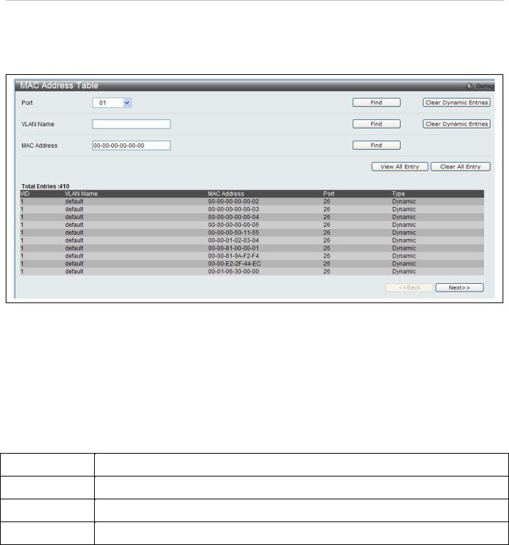
Use the MAC Address Table menu to view or clear entries from the switch's MAC address forwarding data base (FDB) To view this menu, click Switch Configuration > FDB as shown below:
Figure 31. Forwarding Database entry table
Search options include searching by Port number, VLAN Name or specific MAC Address. To search the FDB, select the entry menu for the type of search to conduct (Port, VLAN Name or MAC Address), enter or select the port, VLAN name or MAC address, and click on the Find button.
To scroll through the FDB list manually, click on the Next and Back buttons.
To clear FDB entries choose to clear dynamic entries for a specified Port or VLAN by clicking on the Clear Dynamic Entries button for the search option used. Alternatively, to clear all entries in the FDB, click on the Clear All Entries button.
The MAC Address Table lists the following information:
|
Parameter |
Description |
|
|
|
|
|
VID |
The VID of the VLAN from which packets are forwarded. |
|
|
|
|
|
|
Port |
The corresponding VDSL line of which the VID is a member. |
|
|
|
|
|
|
MAC Address |
The MAC address that resides on the port where traffic is forwarded. |
|
|
|
|
|
|
Type |
The type of FDB entry, Dynamic or Static. |
|
|
|
|
|
|
28
DAS-3626 VDSL2 Switch User Manual
Traffic Segmentation
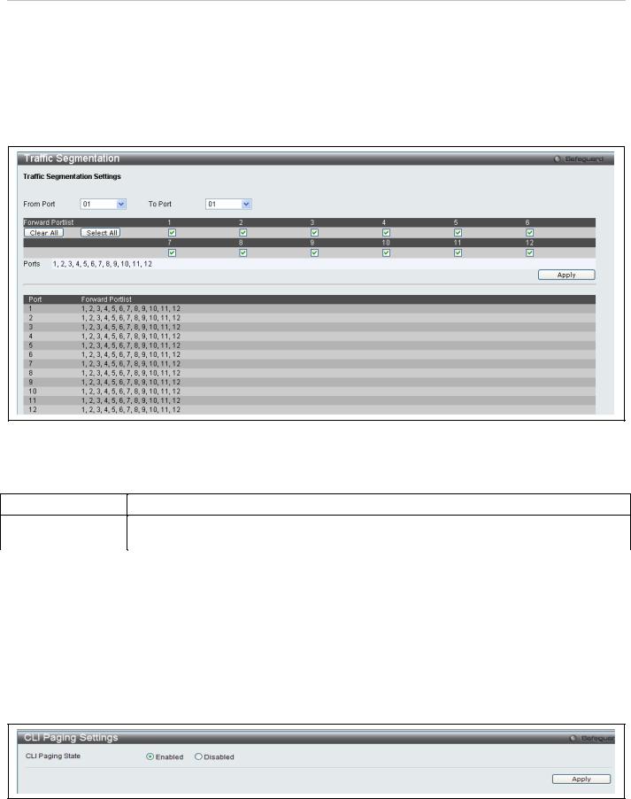
Traffic segmentation is used to limit traffic flow from a single port to a group of ports on either a single switch or a group of ports on another switch in a switch stack. This method of segmenting the flow of traffic is similar to using VLANs to limit traffic, but is more restrictive. It provides a method of directing traffic that does not increase the overhead of the Master switch CPU. This page allows you to view which port on a given switch will be allowed to forward packets to other ports on that switch. Select a port number from the drop down menu to display the forwarding ports. To configure new forwarding ports for a particular port, select a port from the menu and click Apply.
To view this window, click Switch Configuration > Traffic Segmentation as shown below:
Figure 32. Traffic Segmentation menu
The following fields can be set
|
Parameter |
Description |
|
|
|
|
|
From Port / To Port |
Check the corresponding boxes for the port(s) to transmit packets. |
|
|
Forward Portlist |
Check the boxes to select which of the ports on the switch will be able to forward packets. |
|
|
|
|
These ports will be allowed to receive packets from the port specified above. |
|
Clicking the Apply button will enter the combination of transmitting port and allowed receiving ports into the switch's
Current Traffic Segmentation Table.
CLI Paging Settings
Clipaging Status can be Enabled or Disabled in this window, it is Enabled by default. Clipaging settings are used when issuing a command which causes the console screen to rapidly scroll through several pages. This command will cause the console to pause at the end of each page.
To view this menu, click the CLI Paging link in the Quick Configuration menu as shown below:
Figure 33. CLI Paging Settings menu
29
DAS-3626 VDSL2 Switch User Manual
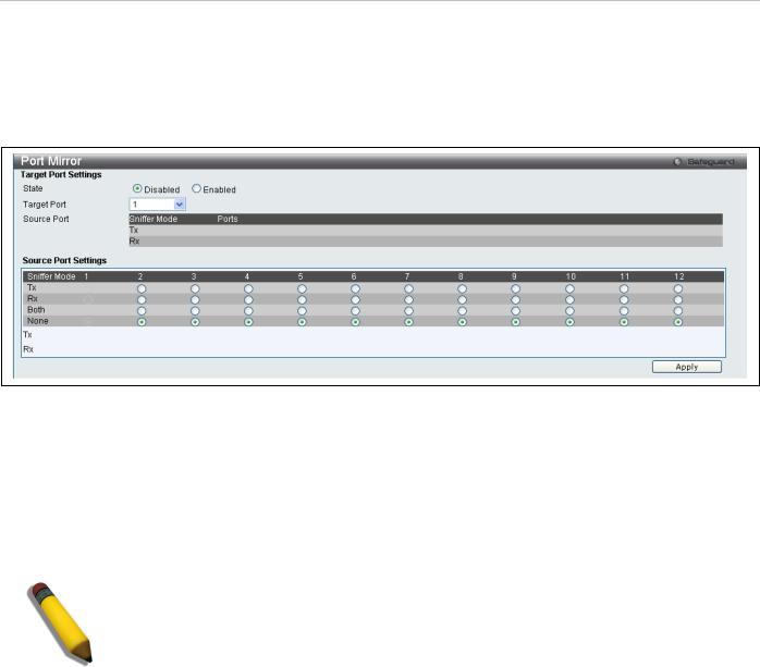
Port Mirror
The switch allows you to copy frames transmitted and received on a port and redirect the copies to another port. You can attach a monitoring device to the mirrored port, such as a sniffer or an RMON probe, to view details about the packets passing through the first port. This is useful for network monitoring and troubleshooting purposes.
To view this window, click Switch Configuration > Port Mirror as shown below:
Figure 34. Port Mirror menu
To configure a mirror port:
1.Change the status to Enabled.
2.Select the Source Port from where you want to the frames to come from.
3.Select the Target Port, which receives the copies from the source port.
4.Click Apply to let the changes take effect.
NOTE: You cannot mirror a fast port onto a slower port. For example, if you try to mirror the traffic from a 100 Mbps port onto a 10 Mbps port, this can cause throughput problems. The port you are copying frames from should always support an equal or lower speed than the port to which you are sending the copies. Also, the target port for the mirroring cannot be a member of a trunk group. Please note a target port and a source port cannot be the same port.
30
Loading...