


D-Link DCS-2000
Internet Camera
Manual
(12/13/2002)
Building Networks for People
Contents |
|
Contents of Package.......................................................................... |
3 |
Introduction ........................................................................................ |
5 |
Features and Benefits ........................................................................ |
5 |
Connections ....................................................................................... |
7 |
Hardware Installation ......................................................................... |
9 |
Software Installation ........................................................................ |
10 |
Installing the Surveillance Software ............................................... |
15 |
Using the DCS-2000 ......................................................................... |
19 |
Firmware Upgrades.......................................................................... |
40 |
Using the Surveillance Software ..................................................... |
42 |
Monitor Program .............................................................................. |
42 |
Playback Program ............................................................................ |
72 |
Appendix ........................................................................................... |
87 |
Frequently Asked Questions ................................................ |
87 |
Troubleshooting .................................................................... |
88 |
How to PING Your IP Address ............................................... |
90 |
Reset and Restore ................................................................. |
91 |
I/O Connector ......................................................................... |
92 |
Adjusting the Cameras Focus .............................................. |
95 |
Replacing the Lens................................................................ |
97 |
Technical Specifications ....................................................... |
98 |
Contacting Technical Support ...................................................... |
100 |
Warranty and Registration ............................................................. |
101 |
2
Package Contents
Contents of Package
D-Link DCS-2000 Internet Camera PowerAdapter
Installation software and manual on CD Quick Installation Guide
Camera Stand
Category 5 Ethernet Cable
If any of the above items are missing, please contact your reseller.
Using a power supply with a different voltage than the one included with the
DCS-2000willcausedamageandvoidthewarrantyforthisproduct.
System Requirements
Internet Explorer 5.x or higher t Web Browser CPU: Pentium III, 500 MHz or above Memory Size: 32 MB (64 MB recommended) VGA card resolution: 800 x 600 or above
These are minimum requirements. Please see Appendix xxx for requirements for various modes of the enclosed Surveillance Software.
3

Cautions and Warnings
Voltage Alert!
The voltage used must be the same as that specified on this unit. Using this product with a higher voltage than is specified is dangerous and may result in a fire or other type of accident causing damage.
For your safety, please do not detach the cover!
To avoid accident of electric shock, please do not attempt to detach the cover of the unit or the DC power supply connector.Customer should contact a qualified technician regarding any repair job.
Caution!
Use of controls or adjustments or performance of procedures other than herein may result in hazardous radiation exposure.
Warning!
Keep the unit away from direct sunlight, strong magnetic fields, excessive dust, humidity and electronic/electrical equipment (home computers, facsimiles, etc.) which generate electrical noise.
4
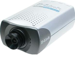
Introduction
The D-Link DCS-2000 Internet Camera is a full featured survellance system that connects to an Ethernet, Fast Ethernet or broadband Internet connection to provide remote high-quality video and audio. The DCS-2000 Internet Camera differs from a conventional PC Camera because the Internet Camera is a stand-alone system with a built-in CPU and Web server providing a low-cost solution capable of solving demanding security and home/office monitoring needs. The Internet Camera can be accessed remotely, and controlled, from any PC or notebook computer over the Internet from anywhere in the world. Simple installation procedures, along with the
built-in Web-based interface offers easy integration to your network environments.
Features and Benefits
The DCS-2000 Internet Camera is a stand-alone system requiring no special hardware or software such as PC frame grabber cards. All that is required is a computer with the Internet Explorer Web browser (version 5.x or above). Just plug-in the camera and view the picture from your Internet Camera with a valid IP Address.
Supports a Variety of Platforms
Supporting TCP/IP networking, SMTP e-mail, HTTP and other Internet related protocols, the Internet Camera can be integrated easily into other Internet/Intranet applications because of its standards-based features.
Broad Range of Applications
With today’s high-speed Internet services, the Internet Camera can provide the ideal solution for live video images over the Intranet and Internet for remote monitoring. The Internet Camera allows remote access from your Internet Explorer Web browser for live image viewing and allows the administrator to manage and control the Internet Camera anywhere and any time in the world. Apply the Internet Camera to monitor various objects and places such as homes, offices, banks, hospitals, child-care centers, amusement parks and other varieties of industrial and public monitoring. The Internet Camera can also be used for intruder detection with its motion-detection
mode, capture still images and video images for archiving and many more applications.
Web Configuration
Using the Internet Explorer Web browser, administrators can configure and manage the Internet Camera directly from its own web page via the Intranet or Internet. Up to 20 user names and passwords are permitted, with privilege settings controlled by the
administrator.
5
Features & Benefits (continued)
Remote Monitoring Utility
The powerful Surveillance Software application assigns an administrator with a predefined user ID and password who can modify the Internet Camera settings from the remote site via an Intranet or the Internet. Users are allowed to monitor the image,
record the image to a hard drive, and take snapshots.
Connection to External Devices
Supporting auxiliary Input/Output connectors, you can connect the Internet Camera to a variety of external devices such as IR-sensors, switches and alarm relays. Combined with programmable alarming facilities, you can develop a variety of security applications that are triggered on alarm-based events. The Internet Camera provides an industry standard in/out external connector for connectivity.
6
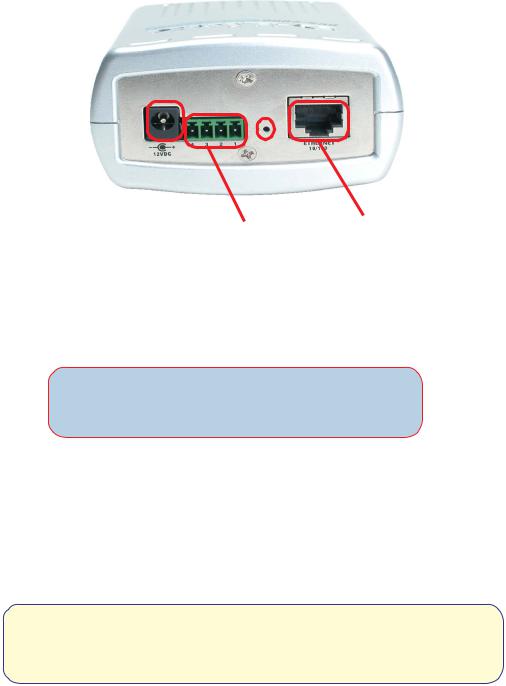
Connections
|
|
|
|
|
Reset Button |
|
|
DC Power |
Connector I/O Connector |
Ethernet Cable |
|
Ethernet Cable Connector
The Internet Camera’s rear panel features an RJ-45 connector for connections to 10Base- T Ethernet cabling or 100Base-TX Fast Ethernet cabling. This network port supports the NWay protocol, allowing the Internet Camera to automatically detect or negotiate the transmission speed of the network.
The Ethernet cable included with the DCS-2000 Internet Camera is a Category 5 cable. This is the recommended cable type when the camera is installed into a 100 Mbps Fast Ethernet network.
DC Power Connector
The DC power input connector is located on the Internet Camera’s rear panel and is labeled DC 12V with a single socket to supply power to the Internet Camera.
Reset Button
Reset will be initiated when the reset button is pressed once and Power LED begins to flash.
Factory reset will be initiated when the reset button is pressed continuously for 5 seconds or when the Power LED begins to light up. Release the reset button and the Power LED will begin to flash indicating that the Internet Camera’s settings are reverting back to the factory settings.
7
Connections (continued)
I/O Connector
There are two I/O connectors,one for input and one for output situated on the rear panel. The I/O connectors provide the physical interface to send and receive digital signals to a variety of external alarm devices. Please refer to the appendix in this manual for detailed information.
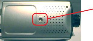
Bottom Panel
Socket for stand
Connecting to the Camera Stand
Located on the bottom panel of the Internet Camera, the socket is used to connect the camera stand onto the Internet Camera by attaching the screw head on the camera stand into the Internet Camera.
Power LED
LED stands for Light-Emitting Diode.
The Power LED is positioned on the right side of the Internet Camera lens. As soon as the power adapter is connected to the Internet camera the power LED will flash red and green several times. The Internet camera is conducting a quick self-test while the LED flashes. Upon passing the self-test the LED will turn green to indicate a good connection to an Ethernet port or red to indicate no connection has been made.
8
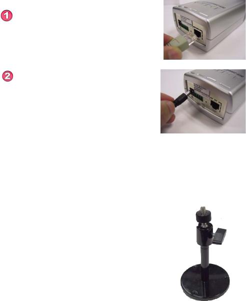
Hardware Installation
Connect an Ethernet cable
Connect an Ethernet cable to the network cable connector located on the Internet Camera’s rear panel and attach it to the network.
Attach the external power supply
Attach the external power supply to the DC power input connector located on the Internet Camera’s rear panel and labeled DC 12V and connect it to your local power supply.
When you have a proper connection the LED will turn from red to green. The light may cycle on and off and your computer may show an intermittant loss of connectivity, this is normal until you have configured your Internet Camera.
Connecting the Internet Camera to the Camera Stand
The Internet Camera comes with a camera stand with a swivel ball screw head that can be attached to the Internet Camera bottom bracket cavity. Attach the camera stand to the Internet Camera and station it for your application. There is a hole located in the base of the camera stand allowing the Internet Camera to be mounted on the ceiling or any wall securely.
9
Software Installation
After you have successfully completed the hardware installation of the DCS2000 Internet Camera, it is necessary to install software to configure and operate the camera. The first step is to run a program on the CD called IP Installer. The program will allow you to use the Internet Camera with you Internet browser. The IP Installer program allows you to enter settings that permit the camera to access the Internet directly or your Ethernet network.
After the IP Installer software program is completed, you will have an operating and controllable Internet Camera. From your Internet Explorer Web browser you will be able to access the video and sound from the Internet camera. The camera has a software program built in (called firmware) built-in Web server. This Web server is the program that allows the camera to access the Internet without an attached computer and permits users to view the video and audio remotely.
After running the IP Installer software program this built-in Web server program, along with your Internet browser, is the only software needed to actually operate the DCS-2000 and view the camera remotely.
However it is necessary to install the Surveillance Software from the enclosed CD to create a truly powerful monitoring and surveillance system. The following section will detail installing the IP Installer and the Surveillance software.
Installing the IP Installer program
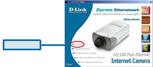
Insert the CD that is included with the DCS-2000 Internet Camera. The IP Installer program will start up automatically from the CD. If it does not (the Windows operating system can turn this autorun function off , for example) simply access the CD from Windows and click on the software program IP Installer.
Click on the Installer button.
Click Installer
10
The opening Installer screen will appear.
IMPORTANT:
A hardware reset of the Internet Camera is now necessary to allow the Installer program to configure the camera correctly. To accomplish this reset, lightly insert a paper clip into the reset hole on the back of the camera (see page7 for the location of the reset hole.) The LED on the front of the camera will begin blinking red and green. When it stops the blinking cycle continue to hold in the reset button until a second cycle of blinking red and green lights indicates a second reset cyle has completed. This will take approximately 5-7 seconds.
The installer will now show a MAC address for the DCS-2000 and an IP address. This IP address may not be correct at this step in the installlation.
Highlight the MAC address and then click on the Wizard button to activate the installation Wizard.
Press Next on the Welcome screen to continue the Wizard.
Click Next
11
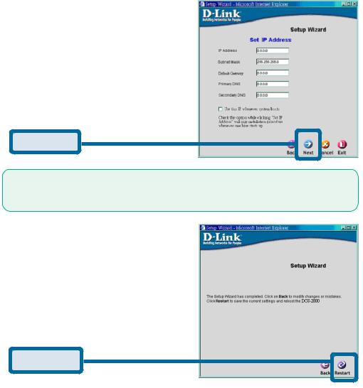
Enter the information needed by the Intrnet Camera to connect with your network or Internet connection. Enter your IP Address, Subnet Mask,
Gateway and at least 1 DNS address. If you do not know what to put in this fields, please contact your network System Adminstrator or your Internet Service Provider.
Click Next
Click the checkbox titled Use this IP whenever systems boots to avoid running this install application each time you boot up the DCS-2000. Only check this if you are sure the IP address being entered will not change the next time the DCS-2000 boots up.
If you need to make any changes, click Back to modify your camera settings. To accept the settings, click Restart.
Click Restart
12
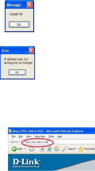
Click OK and the DCS-2000 Internet Camera will reboot to accept the settings.
If the Installer has not made any modifications to the settings, it will warn you that the settings were accepted but no changes were made.
You should now see the opening Installer screen with an IP address assigned to the MAC address of the DCS-2000.
Click on Exit to close the Installer.
You have now completed the Setup Wizard and are ready to use your camera!
Testing the DCS-2000 Internet Camera
Open your Internet browser and type in the IP address of the DCS-2000. In this example the address is: http://192.168.0.146
(your DCS-2000 may have a different IP address based on what you used in the Installer program.)
The window in the center of your browser is the camera image window. You should now see a video image and hear the audio over your computer speakers from the DCS-2000. If you are having problems please consult the Troubleshooting section of this manual.
13
Security
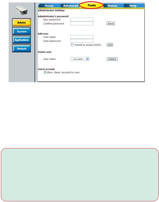
At this point it is highly recommended that you click on the Configuration button on the Home screen, and then the Tools tab to bring you to the Admin screen and enter a password for security purposes.
To ensure the highest security and prevent unauthorized use of the Internet Camera, the Administrator has the exclusive privilege to access the System Administration settings to allow users the security level of entry and authorize privileges for all users. The Internet Camera supports multi-level password protection/access to the Internet Camera that can be restricted to defined users who have a User Name and User Password which is assigned by the Administrator.
The Administrator can release a public user name and password so that when remote users access the Internet Camera they will have the right to view the image transmitted by the Internet Camera.
When the Internet Camera is used for the first time it is highly recommended that the Administrator set the Administrator Password to constrain user access to the Internet Camera since the Default settings are Null String (no password). Once the Password is defined only the Administrator has access to the management of the Internet Camera. This procedure should be done as soon as possible since the security features of the Internet Camera will not be enabled until the
Administrator Password is defined.
14
Installing the Surveillance Software
The Surveillance Software on the CD included with the DCS-2000 Internet
Camera converts the DCS-2000 into a powerful, yet flexible, surveillance system for home or business.
Features and Benefits
•Real-time Monitoring
•Video Recording to hard disk
•High quality video
•High compression ratio
•Maximum to 16 cameras with different monitor layouts
•Smart playback
•Trigged event browsing
•Fast database searching
•Auto alarm in different ways
•Account-password protection
•Scheduled recording for each camera
•Just-in-time snapshot
•AVI export
•Motion detection for each camera
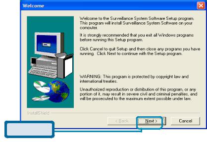
To install the Surveillance Software, click on the Setup file on the CD included with the Internet Camera. The Welcome screen appears:
Click Next
15

Click Yes
Please read the Software Licensing Agreement and click yes if you agree with the agreement. Click “No” to exit.
Click Next
Enter your name and company information and click “Next”.
16
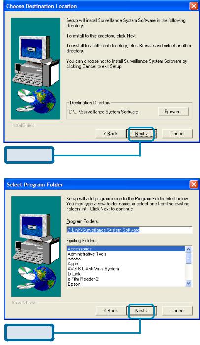
Click Next
Select the destination directory and click “Next”.
Click Next
Select the Program Folder the software will be installed into and click “Next”.
17
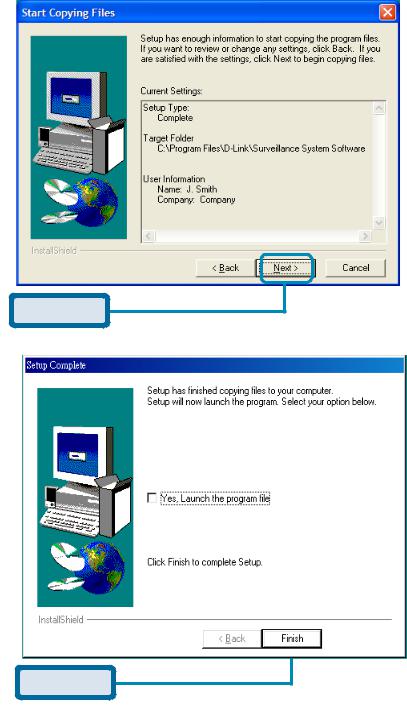
Click Next
Click “Next” and the program will begin copying onto your hard drive.
Click Finish
Click “Finish ” to end the installation.
18
Using the DCS-2000
If you are following this manual in the order it is presented, you should now have an operating DCS-2000 Internet Camera configured with the Installer program. You also have installed the Surveillance Software from the CD. This section of the manual wil deal with using the Internet Camera in two parts:
•Using the DCS-2000 with an Internet browser and accessing the screens to control and monitor the camera.
•Using the Surveillance Software with the DCS-2000.
Using the DCS-2000 with an Internet browser
Open your Internet Explorer Webbrowser and enter the IP address for your Internet Camera.
In the example this address is 192.168.0.146. Your address may differ.
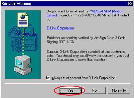
If a window appears asking to install a Versign certificate for authentication D-Link click “Yes”.
19
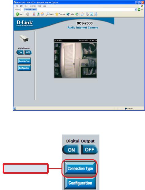
Home Page Screen
The image from the the DCS-2000 should be visible from the Home page on your computer monitor. There are two buttons on the left side of the Home page:
Connection Type and Configuration.
Click Connection Type
Click on the Connection Type button to change settings related to the connection.
20
Home > Connections Screen
The following options are available from the Connections settings screen:
Media Option:
Option for users to disable or enable audio when viewing video.
Protocol Option
The UDP Protocol should be chosen for the most users. Generally the client computer will automatically try these protocols in the following order, UDP -> TCP -> HTTP.
After the client connects to the DCS-2000 successfully, the working protocol will be displayed in “Protocol Option”. The chosen protocol will be recorded in the user’s PC and used for the next connection. If the network environment is changed or users want to let the web browser automatically detect the protocol, select UDP manually and click Save to change the setting and return Home to reconnect with the new setting.
Options:
UDP Protocol - Quality real-time performance compared to TCP. Some packet loss due to network burst traffic and images may be obscure. TCP Protocol - Packet loss is less likely to occur and video displays are more accurate.
HTTP Protocol - If the network is protected by a firewall and it opens HTTP port (80) only, HTTP protocol must be selected. In this mode, audio is disabled and only video can be viewed.
Click the Home tab to return to the DCS-2000 Home page.
21
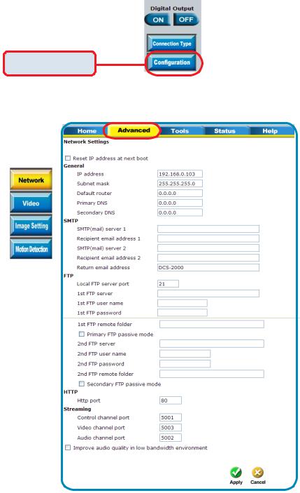
Home > Configuration
Click on the Configuration button on the Home page:
Click Configuration
There are 5 tabs across the top of the Configuration screen controlling different elements the DCS-2000 can configure. The Advanced tab is the default screen in Configuration and Network is the default screen under
Advanced.
22

Configuration > Advanced > Network Settings
Any changes made to these settings will require the system to restart to validate. Make sure every field is correctly typed before clicking on:
Reset IP address at next boot
The box is checked when first installed.To avoid performing a software installation whenever the DCS-2000 starts, and once the network settings, especially the IP address, are correct, uncheck this box. This option can also be disabled using the IP Installer program. Once the option is disabled, the DCS-2000 will skip installation at the next boot and the IP Installer program will no longer find the installed units if any changes are necessary to the network settings. It may be necessary in that case to to recover the DCS-2000 by restoring factory default settings. However, with this option disabled the DCS-2000 can automatically operate normally after restarting in case of losing power.
General
IP address - |
Necessary for network identification. |
Subnet mask - |
Used to determine if the destination is in the same |
Default router - |
subnet. The default value is “255.255.255.0”. |
The gateway used to forward frames to destinations |
|
|
in a different subnet. Invalid router setting will fail in |
Primary DNS - |
transmission to destinations in different subnet. |
Primary domain name server who translates names |
|
Secondary DNS - |
to IP addresses. |
Secondary domain name server to backup the |
|
|
primary one. |
SMTP |
|
SMTP(mail) server 1 - |
The domain name or IP address of external email |
|
server. |
Recipient email address 1 - The email address of recipients for snapshots or log
|
file. Multiple recipients must be separated by |
SMTP(mail) server 2 - |
semicolon, ‘;’. |
The domain name or IP address of another email |
|
|
server once the previous server is unreachable. |
Recipient email address 2 - the email address of recipients for the backup server.
Return email address |
The return email address once the mails fail to send |
|
out. |
|
Continued on Next Page |
23

Configuration > Advanced >Network Settings (continued)
FTP Settings
Local FTP server port -
1st FTP server -
1st FTP user name - 1st FTP password - 1st FTP remote folder -
Primary FTP passive mode -
2nd FTP server -
2nd FTP user name - 2nd FTP password - 2nd FTP remote folder -
Secondary FTP passive Mode -
It can be other than default port 21. After changing, the external FTP client program must change the server port of the connection accordingly.
The domain name or IP address of the external FTP server. The following user settings must be correctly configured for remote access.
Granted user name on the external FTP server. Granted password on the external FTP server. Granted folder on the external FTP server. The string must conform to the external FTP server. Some FTP servers cannot accept a preceding slash symbol before the path if there is no virtual path mapping. Refer to the instructions of the external FTP server for details. The folder privilege must be open for upload.
If the DCS-2000 is located inside the network protected by firewall, a data connection for FTP may be prohibited. Passive mode FTP can bypass the rule and succeed to upload snapshots. If the passive mode is selected, the DCS-2000 can automatically attempt for an active mode if the external FTP server does not support passive mode.
The domain name or IP address of the external FTP server.
Granted user name on the backup FTP server. Granted password on the backup FTP server. Granted folder on the backup FTP server.
Passive mode setting for the backup FTP server.
HTTP Settings
Http port - |
Can be to other than the default port 80. Once the |
|
port is changed, users must be informed for |
|
successful connection. For instance, when the |
|
administrator changes the HTTP port of the DCS- |
|
2000, whose IP address is 192.168.0.100 from 80 to |
|
8080, users must type in the web browser |
|
“http://192.168.0.100:8080” instead of |
|
“http://192.168.0.100”. |
Click Apply to make changes effective
24
Configuration > Advanced >Network Settings (continued)
Streaming Screen
Control channel port - |
It can be other than default port 5001 to cooperate |
Audio channel port - |
with the port opened by the firewall. |
It can be other than default port 5002 to cooperate |
|
Video channel port - |
with the port opened by the firewall. |
It can be other than default port 5003 to cooperate |
|
Improve audio quality in |
with the port opened by the firewall. |
|
|
low bandwidth |
|
environment - |
In a low network bandwidth environment, users can |
|
check this option to improving audio quality by |
|
sacrificing some real-time synchronization. |
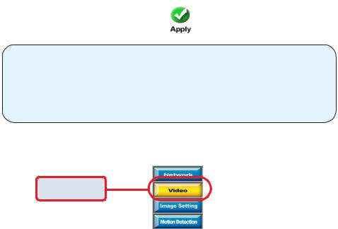
Click Apply to make changes effective
Some invalid settings may cause system failure to respond. Change the configuration only if necessary and consult with network supervisor or experienced users for correct settings. Once the system is lost contact, refer to Appendix A for reset and restore procedures.
Configuration > Advanced > Video Settings
Click Video
Click the video button from the Configuration screen to access video settings that effect how the video image appears.
25
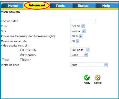
Configuration > Advanced > Video Settings
Text on video - |
Text will be displayed in the black bar above the |
|
video window with a timestamp. The timestamp is |
|
captured from the date and time of the DCS-2000 |
Color - |
and is maintained by a built-in real-time clock. |
Select the option for color or monochrome video |
|
|
display. |
Size - |
There are three options for two video sizes. “Half” is |
|
a quarter size of “Normal”. “Half x 2” has the |
|
same video size as “Normal” but has worse quality. |
Power line frequency |
However it consumes less network bandwidth. |
|
|
(for fluorescent light) - |
The fluorescent light will flash according to the power |
|
line frequency and depends on the local utility. |
|
Change the frequency setting to eliminate |
|
uncomfortable flash image when the light source is |
|
only fluorescent light. |
26
Configuration > Advanced > Video Settings
There are three dependent parameters provided for video performance adjustment.
Maximum frame rate- |
Limits the maximal refresh frame rate that can be |
|
combined with the “Video quality control” to |
|
optimize the bandwidth utilization and video quality. If |
|
users want to fix the bandwidth utilization regardless |
|
of the video quality, choose “Fix bit rate” and |
|
select the desired bandwidth. The video quality may |
|
be poor in order to send maximal frames within the |
|
limited bandwidth when images change drastically. |
|
Consequently to ensure the video detail (quantization |
|
rate) regardless of the network, it will utilize more |
|
bandwidth to send the maximal frames when images |
|
change drastically. |
Flip - |
Vertically rotate the video. |
Mirror - |
Horizontally rotate the video. Check both if DCS- |
|
2000 is installed upside down. |
White balance - |
Choose the suitable option for the best color |
|
temperature. |
Tune Video for the best performance
“Best performance” means the image refresh rate should be the fastest possible and the video quality should be the best possible at the lowest network bandwidth possible. Three factors, “Maximum frame rate”, “Fix bit rate”, and “Fix quality” in the Video configuration page, are related to the performance.
My priority is real-time motion images
To achieve a real-time visual effect, the network bandwidth should be large enough to transmit 20 image frames per second (fps) or more. If you are on a broadband network over 1 Mbps, you can fix the bit rate to 1000Kbps or 1200Kbps, or fix the quality to achieve the maximum frames. The maximum frame rate is 25 in 50Hz system and 30 in 60Hz system. If your network bandwidth is more than 384Kbps, you can fix the bit rate according to your bandwidth and set the maximum frame rate to 25 or 30. If the images vary dramatically in your environment, you may slow down the maximum frame rate to 20 to decrease the transmitted data for better video quality, since the human eye could not easily tell the difference between 20 and 25 or 30 frames per second. If your network bandwidth is below 384 Kbps, you should fix the bit rate according to your bandwidth and try out the best performance by tuning the maximum frame rate. The larger frame rate in slow network will blur the images. You may also try to choose “Half” in size option for better images or “Halfx2” for larger image size. Because the network has burst constraints and everyone’s environment is not the same, any poor connection will drop the normal performance.
27
Tune Video for the best performance (continued)
My priority is clear identification for each image
To have the best video quality, you should fix the quality to detailed or excellent and tune the maximum frame rate to suit for your network bandwidth. If you get some broken pictures in a slow network, you can choose TCP protocol in “Connection type” for more accurate transmission but the received images may have certain time delay. Note that any slow connection in with multiple users will drop the performance.
I want to compromise between real-time and clear images
If you have a broadband network, choose fix quality to normal or better rather than fix the bandwidth. Otherwise fix the bandwidth according to your actual network speed and set the frame rate to 30. If the images look bad, select the lower frame rate above 15. If the images are not improved, select the lower bandwidth.
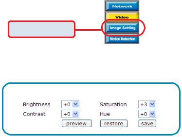
Configuration > Advanced > Image Settings
Click Image Settings
Click the video button from the Configuration screen to access video settings that effect how the video image appears.
From this screen you can fine tune the video image.
Brightness” “Contrast” “Saturation” and “Hue”are all adjusted in the same manner. For each video compensation you can set from among eleven levels ranged from -5 to +5.
You may press  to fine-tune the image and see what effect the setting will have on the image. When the image is acceptable, press
  to memorize the image settings or
  to recall the original settings. If parameters are changed without saving, they will be used until the next system startup.
28
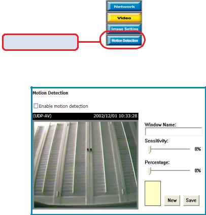
Configuration > Advanced > Motion Detection
Click Motion Detection
Click the Motion Detection button from the Configuration screen to access settings that effect how the DCS-2000 Internet Camera can serve as a security device by recording only when motion is detected.
Enable motion detection - |
Check this option to turn on the motion detection. |
New - |
Click on this button to add a new window. At most, |
|
three windows can exist at the same time. Use the |
|
mouse to drag the window frame to resize or the title |
|
bar to move. Clicking on the ‘x’ at the upper right |
|
corner of the window can delete the window. |
|
Remember to save to validate the changes. |
Save - |
Click on this button to save the related settings |
|
regarding to the window. A graphic bar will rise or fall |
|
depending on the image variation. A green bar means |
|
the image variation is under monitoring level and a |
|
red bar means the image variation is over monitoring |
|
level. When the bar goes red, the detected window |
|
will also be outlined in red. While back to the |
|
homepage, the monitored window will hide but the |
|
red frame will show when motion is detected. |
29
Configuration > Advanced >Motion Detection (continued)
Window Name - |
The text entered here will show at the top of the |
|
window. |
Sensitivity - |
Sets the measurable difference between two |
|
sequential images that would indicate motion. |
Percentage - |
Decides the space ratio of motioned objects over the |
|
monitored window. Higher sensitivity and small |
|
percentage will make any motion more easily |
|
detected. |
30
 Loading...