


 Loading...
Application Note
 Slave Controller
Development Products
Frequently Asked Questions and
Troubleshooting
ET1100
ET1200
EtherCAT IP Core
Version 1.1
Date: 2011-12-15

DOCUMENT HISTORY
|
|
|
|
|
DOCUMENT HISTORY |
|
|
|
|
|
|
|
|
|
Version |
|
|
|
Comment |
|
|
|
|
|
|
|
|
|
1.0 |
|
|
|
Initial release |
|
|
|
|
|
|
|
|
|
1.1 |
|
|
|
Added chapter on missing RSA key in Xilinx® EDK |
|
|
|
|
|
|
Added error counter interpretation guide |
|
|
|
|
|
|
Added appendix on showing error counters in TwinCAT |
|
Trademarks
Beckhoff®, TwinCAT®, EtherCAT®, Safety over EtherCAT®, TwinSAFE® and XFC® are registered trademarks of and licensed by Beckhoff Automation GmbH. Other designations used in this publication may be trademarks whose use by third parties for their own purposes could violate the rights of the owners.
Patent Pending
The EtherCAT Technology is covered, including but not limited to the following German patent applications and patents: DE10304637, DE102004044764, DE102005009224, DE102007017835 with corresponding applications or registrations in various other countries.
Disclaimer
The documentation has been prepared with care. The products described are, however, constantly under development. For that reason the documentation is not in every case checked for consistency with performance data, standards or other characteristics. In the event that it contains technical or editorial errors, we retain the right to make alterations at any time and without warning. No claims for the modification of products that have already been supplied may be made on the basis of the data, diagrams and descriptions in this documentation.
Copyright
© Beckhoff Automation GmbH 12/2011.
The reproduction, distribution and utilization of this document as well as the communication of its contents to others without express authorization are prohibited. Offenders will be held liable for the payment of damages. All rights reserved in the event of the grant of a patent, utility model or design.
II |
Slave Controller – Application Note FAQ |

|
|
|
CONTENTS |
|
|
|
|
CONTENTS |
|
1 |
Introduction |
|
|
1 |
2 |
Frequently unasked questions |
2 |
||
|
2.1 |
What information should I provide when I need support? |
2 |
|
3 |
General Issues |
|
3 |
|
|
3.1 |
Where can I find documentation updates? |
3 |
|
|
3.2 |
ESC clock source accuracy: Is 25 ppm necessary? |
3 |
|
|
3.3 |
Why should port 0 never be an unused port? |
3 |
|
|
3.4 |
Link/Activity LEDs shows strange behavior |
3 |
|
|
3.5 |
Can slaves communicate without SII EEPROM / invalid SII EEPROM content? |
3 |
|
|
3.6 |
Do I need the complete XML ESI description for simple PDI read/write tests? |
3 |
|
|
3.7 |
What do I do with unused ports (EBUS/MII) |
4 |
|
|
3.8 |
Resetting ESC, PHYs, and µController |
4 |
|
|
3.9 |
Should I enable Enhanced Link Detection? |
5 |
|
|
3.10 |
Why must I configure the PHYs for auto-negotiation instead of forcing 100 |
|
|
|
Mbit+FD? |
|
5 |
|
|
3.11 |
What is TX Shift and Auto TX Shift? |
5 |
|
|
3.12 |
Frames are lost / communication errors are counted |
6 |
|
|
|
3.12.1 |
Configuring TwinCAT to show the ESC error counters |
6 |
|
|
3.12.2 |
Reduce the complexity |
6 |
|
|
3.12.3 |
Basic error counter interpretation |
7 |
|
|
3.12.4 |
Error counter interpretation guide |
8 |
|
3.13 |
PDI Performance |
10 |
|
|
3.14 |
Interrupts |
|
11 |
|
|
3.14.1 |
µControllers with edge-triggered Interrupt / only the first interrupt is |
|
|
|
processed |
11 |
|
|
|
3.14.2 |
Polling and Interrupt handling |
11 |
|
3.15 |
Distributed Clocks: Resolution, Precision, Accuracy |
12 |
|
|
3.16 |
Hardware not working |
13 |
|
4 |
EtherCAT IP Core for Altera FPGAs |
14 |
||
|
4.1 |
Licensing issues |
14 |
|
|
|
4.1.1 |
Check license status |
14 |
|
|
4.1.2 |
Compare license file and Quartus II License Setup |
15 |
|
|
4.1.3 |
No license found |
16 |
|
|
4.1.4 |
License expired |
17 |
|
|
4.1.5 |
OpenCore Plus License Identification |
18 |
|
4.2 |
Implementation issues |
19 |
|
|
|
4.2.1 |
MegaWizard generation |
19 |
|
|
4.2.2 |
Analysis & Synthesis |
20 |
|
|
|
4.2.2.1 Checking the actual EtherCAT IP Core configuration |
20 |
|
|
|
4.2.2.2 Vendor ID package is in the project, but not on the disk |
21 |
|
|
|
||
|
Slave Controller – Application Note FAQ |
III |
||

CONTENTS
4.2.2.3 |
Vendor ID package is not in the project |
21 |
4.2.2.4 |
Important logic parts or I/O signals are optimized away, |
|
|
hardware does not work |
22 |
|
|
4.2.3 |
Library files are not copied to project (reference designs) |
23 |
|
|
4.2.4 |
Additional signals (SIM_FAST, PHY_OFFSET) in the pinout report |
24 |
|
|
4.2.5 |
Timing closure issues |
26 |
|
|
|
4.2.5.1 OpenCore Plus logic does not achieve timing |
|
|
|
|
(altera_reserved_tck) |
26 |
|
|
|
4.2.5.2 General timing closure issues |
26 |
|
4.3 |
Hardware issues |
27 |
|
|
4.4 |
OpenCore Plus design stops operating too early |
27 |
|
5 |
EtherCAT IP Core for Xilinx FPGAs |
28 |
||
|
5.1 |
Project navigator/EDK crashes |
28 |
|
|
5.2 |
Licensing issues |
29 |
|
|
|
5.2.1 |
Check license status |
29 |
|
|
5.2.2 |
Compare license file and Xilinx License Configuration Manager |
30 |
|
|
5.2.3 |
No license found |
31 |
|
|
5.2.4 |
Evaluation License Identification |
32 |
|
|
|
5.2.4.1 Installed license file |
32 |
|
|
|
5.2.4.2 Installed EtherCAT IP Core |
32 |
|
|
5.2.5 |
Vendor ID package missing |
33 |
|
5.3 |
Implementation issues |
34 |
|
|
|
5.3.1 |
XST |
34 |
|
|
|
5.3.1.1 RSA decryption keys missing (ISE) |
34 |
|
|
|
5.3.1.2 RSA decryption keys missing (EDK) |
35 |
|
|
|
5.3.1.3 Checking the actual EtherCAT IP Core configuration |
36 |
|
|
5.3.2 |
Place & Route |
37 |
|
|
|
5.3.2.1 CLOCK_DEDICATED_ROUTE=FALSE with SPI reference |
|
|
|
|
design |
37 |
|
|
5.3.3 |
PlanAhead |
38 |
|
|
|
5.3.3.1 PlanAhead implementation/floorplaning/analysis is not possible38 |
|
|
|
5.3.4 |
General timing closure issues |
39 |
|
5.4 |
Hardware issues |
40 |
|
6 |
Appendix |
|
|
41 |
|
6.1 |
Logging Error Counters in TwinCAT |
41 |
|
|
6.2 |
TwinCAT hints |
47 |
|
|
6.3 |
Support and Service |
48 |
|
|
|
6.3.1 |
Beckhoff’s branch offices and representatives |
48 |
|
6.4 |
Beckhoff Headquarters |
48 |
|
IV |
Slave Controller – Application Note FAQ |

Introduction
1 Introduction
Purpose of this document is to answer common questions regarding EtherCAT development products and to avoid common implementation mistakes which came up in the past.
This document is aiming at the following Beckhoff ESCs:
ET1200 (up to ET1200-0002)
ET1100 (up to ET1100-0002)
EtherCAT IP Core for Altera® FPGAs (up to V2.4.0)
EtherCAT IP Core for Xilinx® FPGAs (up to V2.04a)
Slave Controller – Application Note FAQ |
1 |

Frequently unasked questions
2 Frequently unasked questions
2.1What information should I provide when I need support?
Sometimes the documentation and this FAQ do not offer a solution for your problem and you need support. You can improve your support experience by providing precise and complete information, which helps us identifying the problem faster.
Please provide the following information when contacting the support:
Detailed error description with the following background information (if appropriate): o network topology
o how often does the error occur
o ESC type (ET1100, ET1200, IP Core, other)
o ESC version (ASICs: e.g. -0002, IP Core: Altera/Xilinx and version) o are frames lost, are error counters increasing (refer to chapter 3.12)
IP Core: IP Core configuration (Altera: MegaFunction source, Xilinx: .eccnf file)
IP Core: complete report log files: do not extract single lines – the context of the error is very important.
Schematics of the ESC/FPGA and the PHYs
IP Core: top level schematics/sources of the FPGA which shows EtherCAT IP Core connections.
EtherCAT master type and version (if applicable)
2 |
Slave Controller – Application Note FAQ |

General Issues
3 General Issues
3.1Where can I find documentation updates?
Documentation updates are available for download at the BECKHOFF website: http://www.beckhoff.de/english/download/ethercat_development_products.htm
3.2ESC clock source accuracy: Is 25 ppm necessary?
Since standard PCs can be used as a master, the clock source deviation of the master’s Ethernet PHY can be up to 100ppm. This is tolerated by the ESCs (according to IEEE 802.3) if the FIFO size is default. Nevertheless, EtherCAT requires 25 ppm clock accuracy for the EtherCAT slaves in order to enable FIFO size reduction.
FIFO size reduction is possible in any slave with high accuracy except for the first one directly attached to the master. This can reduce network latency significantly, so, 25 ppm is mandatory. Additionally, the clock accuracy has influence on the DC settling time and the forwarding latency jitter.
3.3Why should port 0 never be an unused port?
Refer to the special features of port 0: If a frame travels through a slave with port 0 automatically closed (because it is unused, the link state is fixed at no link), the Circulating Frame bit is set in the frame. If this frame comes to a second device which has also port 0 automatically closed (because unused), the frame will be destroyed.
So, any network containing more than one of the slaves with port 0 unused will experience impossible communication. Additionally, in case of network trouble, masters might try to close ports in order to isolate faulty network segments and to maintain communication in the rest of the network. If port 0 is not used, the master is connected via port 1, 2 or 3. The master might try to close ports 1, 2, or 3 because it expects to be located at port 0, which results in network isolation.
Refer to the ESC datasheet section I for more information on port 0 special behaviour.
3.4Link/Activity LEDs shows strange behavior
LED is on without anything attached, LED is off with other device attached. If all ports are connected, communication with the slave is possible, although following slaves are not seen.
This happens if the LINK_MII polarity is incorrect, i.e. the link information is inverted for the ESC. The communication with the slave is possible if all ports are connected, because the ESC detects that no port has a link, and then it automatically opens port 0. You can check this in ESC DL status register 0x0110: no physical link at all ports (although you can obviously read through port 0).
3.5Can slaves communicate without SII EEPROM / invalid SII EEPROM content?
Yes! EtherCAT communication is possible; all frames can be forwarded without a problem. Register reading/writing is possible, but process data exchange is impossible. The ESC blocks Process Data memory until the EEPROM is successfully loaded (typically no PDI is configured unless the SII EEPROM is loaded successfully). You can do the initial programming of the SII EEPROM via EtherCAT (e.g. for hundreds of slaves with “empty” SII EEPROM in parallel (broadcast).
3.6Do I need the complete XML ESI description for simple PDI read/write tests?
No, you do not need a complete ESI for PDI read/write tests. Only the first 8 words of the SII EEPROM need to be written (e.g. via the network with values from the pinout configurator, the IP core configurator, or the ESI EEPROM CRC calculator). This enables the PDI interface. Such a device cannot be correctly identified by TwinCAT, but basic frame exchange (register view etc.) is possible.
Slave Controller – Application Note FAQ |
3 |
General Issues
3.7What do I do with unused ports (EBUS/MII)
EBUS
Attach RX resistor, leave TX signals open. If EBUS is not used at all, the tolerance of the RBIAS resistor is increased to 1kΩ (i.e., you could set RBIAS to 10 kΩ).
MII
Set LINK_MII to indicate no link (value depends on link polarity configuration), leave TX signals open, pull-down RX signals (should not be left floating). Leave pull-up for MDC/MDIO in the design, so that the interface can detect the state correctly..
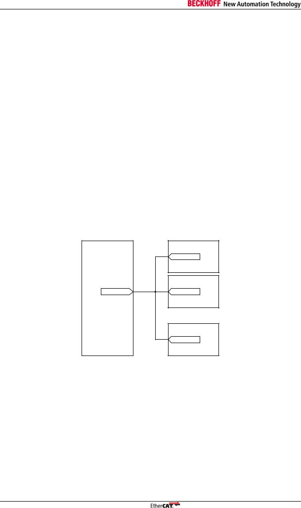
3.8Resetting ESC, PHYs, and µController
All Ethernet PHYs should be hold in reset state until the ESC leaves reset state. With the EtherCAT ASICs, make use of the nRESET signal. With FPGAs, you should route the nRESET signal out of the FPGA. Make sure the PHYs are in reset state while the FPGA is loading. If FX transceivers are used, make also sure that the transceivers are disabled (powered down) while the ESC is not operational
(refer to the AN “PHY selection guide” for more details).
The reason is that otherwise the PHYs will establish a link with the neighbours, these neighbours will open their link, but communication is not possible because the ESC is not operational. The result will be frame loss, which is not desired.
If EEPROM emulation is used, the µController should be able to process EEPROM commands once communication is possible, otherwise an EtherCAT master might time-out.
A µController attached to the PDI should also be reset by the ESC (e.g. by a soft reset via register 0x0040:0x0041).
ESC |
Ethernet PHY |
|
nRESET |
|
Ethernet PHY |
nRESET |
nRESET |
µController
nRESET
Figure 1: Reset connection principle
Refer to the ESC datasheet and the AN PHY selection guide for more information.
4 |
Slave Controller – Application Note FAQ |

General Issues
3.9Should I enable Enhanced Link Detection?
For MII ports, a precondition for Enhanced Link Detection is that the MII management interface is operating with all PHYs (PHY address configuration ok), which is strongly recommended anyway. If the ESC has only MII ports, Enhanced Link Detection is recommended regardless of the PHY link loss reaction time. If the Enhanced Link Detection can be enabled port-wise, it is recommended to enable it for each MII port.
If the ESC has one or more EBUS ports, Enhanced Link Detection must remain disabled for ET1200 and ET1100. This is also true if the PHY offset for ET1200 or ET1100 is not zero.
Refer to the ESC datasheet section I for more information about Enhanced Link Detection.
3.10 Why must I configure the PHYs for auto-negotiation instead of forcing 100 Mbit+FD?
EtherCAT requires that the Ethernet PHYs are configured to use auto-negotiation, and not 100 Mbit + full duplex in force mode. The reason is interoperability.
While two devices which are forced to 100 Mbit + full duplex (FD) are perfectly operating together with EtherCAT, a problem arises if one device uses auto-negotiation, and the other one forced mode. In this case, the auto-negotiation device will fall back to 100 Mbit + half duplex (HD), because it has no knowledge of the capabilities of the link partner. The half-duplex operation can lead to communication issues especially at the master, but probably also at the slaves. That is why auto-negotiation is mandatory for EtherCAT PHYs.
Another issue is the Auto-MDIX feature of the PHYs, which often depends on auto-negotiation being enabled. So, without auto-negotiation, some EtherCAT links would require a cross-over cable, others a straight cable, which complicates the situation even more.
Refer to the AN PHY selection guide for more information.
3.11 What is TX Shift and Auto TX Shift?
Beckhoff ESCs are not incorporating transmit (TX) FIFOs for the MII interfaces to reduce the latency. Nevertheless, the PHYs have certain timing requirements for the TX signals (setup/hold), which have to be fulfilled. The TX Shift configuration is used to move the TX signal timing to a valid window manually. With Auto TX Shift, the ESC automatically figures out the correct shift value and shifts the TX signals accordingly. Nevertheless, Auto TX Shift is not the same as a TX FIFO, it still requires synchronous clocking of the ESC and the PHY.
Refer to the ESC datasheet for more information about TX Shift and Auto TX Shift.
Slave Controller – Application Note FAQ |
5 |

General Issues
3.12 Frames are lost / communication errors are counted
During power-up, it is a normal behaviour of the ESCs to count a few communication errors. You can typically ignore them, only new errors which occur during operation are significant. An exception is the PDI error counter, which is expected to be zero after power-up.
Generally, no real bus system is completely error-free, i.e., the bit error rate (BER) is never zero. A few individual errors over time are tolerated by EtherCAT. It needs several errors or lost frames in a row to interrupt the operation of a part of the network. Again, the PDI error counter is an exception, it has to be zero all the time.
If frames are lost or error counters are increasing, configure TwinCAT to show the ESC error counters and use the error counter interpretation guide in this chapter.
Refer to the ESC datasheet section I and II for more information on the ESC error counters.
3.12.1 Configuring TwinCAT to show the ESC error counters
Refer to the appendix (chapter 6.1) for details on configuring TwinCAT for displaying all the ESC error counters. This helps in identifying the problem.
3.12.2 Reduce the complexity
Try reducing the complexity of the problem, which helps in localizing the problem cause:
Try reducing the network size to a minimum, while the error is still present.
Disable Enhanced Link Detection for testing to improve error visibility.
Swap devices in the network to isolate the error source.
6 |
Slave Controller – Application Note FAQ |
General Issues
3.12.3 Basic error counter interpretation
At first, check the ESC configuration, e.g. by viewing the POR registers 0x0E00:0x0E01 or the IP Core configuration in the User RAM 0x0F80. If the configuration is wrong, check the strapping options and power-on signal values during POR sampling.
Then, check the link status in the ESC DL Status register 0x0110. If there is something wrong with the link status, check the LINK_MII signal. If this is also ok, the problem is in the area PHY – connector – cable – connector – PHY.
If an RX Error counter (0x0301, 0x0303, 0x0305, 0x0307) is increasing, there is a problem in the area PHY – connector – cable – connector – PHY. Measure the RX_ERR signal from the PHY to prove the error counter: if it is sometimes high, check the cabling, connectors, and PHY. Measure the RX_ERR signal from the PHY. The ESC is not the source of the problem.
If there is no RX Error, there is probably a master issue. Use a proven master, attach also proven slaves. Remove DUT; move the DUT in the network by swapping positions and check if the error is moving with the DUT.
If the issue is not a master issue, it must be in the area PHY – ESC – PHY, i.e., check the interface configuration of the PHY, the connections itself, the configuration of the ESC, and – in case of the IP Core –, if the ESC is correctly constrained and the timing is achieved.
Also think of power supply break-down, clock jitter, and glitches on the reset signal.
Slave Controller – Application Note FAQ |
7 |

General Issues
3.12.4 Error counter interpretation guide
The following diagram can be used to identify possible error causes. At first, find out which error counters are increasing in your network (or device), and at the master. Compare this with each of the cases shown in the main table of Figure 2 and find the most similar case. Follow the arrows at the bottom of each column to the possible error causes. Use Table 1 for comments and error localization.
Error counter |
|
Register |
|
|
|
|
|
|
|
|
|
|
|
|
|
|
|
|
|
|
Cases |
|
|
|
|
|
|
|
|
|
|
|
|
|
|
|
|
+ |
|
|
Increasing |
||||||
|
|
|
|
|
|
|
|
|
|
|
|
|
|
|
|
|
|
|
|
|
|
|
|
|
|
|
|
|
|
|
|
|
|
|
|
|
|
||||||||||
|
|
|
|
|
|
|
|
|
|
|
|
|
|
|
|
|
|
|
|
|
|
|
|
|
|
|
|
|
|
|
|
|
|
|
|
|
|
|
|
|
|
|
|
|
|
||
|
|
|
|
|
1 |
2 |
3 |
4 |
5 |
|
6 |
7 |
|
8 |
9 |
|
10 |
11 |
12 |
13 |
14 |
15 |
16 |
17 |
|
|
(+) |
Might be increasing/ |
|||||||||||||||||||
|
|
|
|
|
|
|
|
|
|
|
|
available |
|||||||||||||||||||||||||||||||||||
Lost frame |
|
Master |
|
|
|
|
+ |
+ |
|
|
|
+ |
|
|
|
|
|
+ |
+ |
|
|
+ |
+ |
+ |
+ |
|
|
|
|
|
|
-- |
|
No data / no |
|||||||||||||
|
|
|
|
|
|
|
|
|
|
|
|
|
|
|
|
|
|
|
|
|
|
communication |
|||||||||||||||||||||||||
|
|
|
|
|
|
|
|
|
|
|
|
|
|
|
|
|
|
|
|
|
|
|
|
|
|
|
|
|
|
|
|
|
|
|
|
|
|
|
|
|
|
|
|
|
|
|
|
TwinCAT RX Err |
|
Master |
|
|
|
|
|
|
|
|
+ |
+ |
|
|
|
|
|
|
|
|
|
|
|
|
|
|
|
|
|
|
|
|
|
|
|
|
|
|
|
|
Common cause |
||||||
|
|
|
|
|
|
|
|
|
|
|
|
|
|
|
|
|
|
|
|
|
|
|
|
|
|
|
|
|
|
|
|
|
|
|
|
|
|
|
|
|
|
||||||
|
|
|
|
|
|
|
|
|
|
|
|
|
|
|
|
|
|
|
|
|
|
|
|
|
|
|
|
|
|
|
|
|
|
|
|
|
|
|
|
|
|
|
|
|
|
|
|
TwinCAT TX Err |
|
Master |
+ |
|
|
|
|
|
|
|
|
|
|
|
|
|
|
|
|
|
|
|
|
|
|
|
|
|
|
|
|
|
|
|
|
|
|
|
|
|
|
|
Unusual cause |
||||
|
|
|
|
|
|
|
|
|
|
|
|
|
|
|
|
|
|
|
|
|
|
|
|
|
|
|
|
|
|
|
|
|
|
|
|
|
|
|
|
|
|
|
|
|
|
||
ESC CRC Err |
0x0300 (+2/4/6) |
|
|
|
|
|
|
-- |
|
|
|
|
|
|
|
|
|
|
+ |
+ |
|
|
+ |
|
|
|
|
|
|
+ |
|
|
|
|
|
|
|
|
|||||||||
|
|
|
|
|
|
|
|
|
|
|
|
|
|
|
|
|
|
|
|
|
|
|
|
|
|
|
|
|
|
|
|
|
|
|
|
|
|
|
|
|
|
|
|||||
|
|
|
|
|
|
|
|
|
|
|
|
|
|
|
|
|
|
|
|
|
|
|
|
|
|
|
|
|
|
|
|
|
|
|
|
|
|
|
|
|
|
|
|
||||
ESC RX Err |
0x0301 (+2/4/6) |
|
|
|
|
|
|
-- |
|
|
|
|
|
+ |
+ |
+ |
+ |
|
|
|
|
|
|
|
|
|
|
|
|
|
|
|
|
|
|
|
|
||||||||||
|
|
|
|
|
|
|
|
|
|
|
|
|
|
|
|
|
|
|
|
|
|
|
|
|
|
|
|
|
|
|
|
|
|
|
|
|
|
|
|
|
|
|
|||||
|
|
|
|
|
|
|
|
|
|
|
|
|
|
|
|
|
|
|
|
|
|
|
|
|
|
|
|
|
|
|
|
|
|
|
|
|
|
|
|
|
|
|
|
|
|
||
ESC Forw. Err. |
0x0308 (+1/2/3) |
|
|
(+) |
|
|
-- |
|
|
|
|
|
|
|
|
|
|
(+) |
(+) |
|
|
(+) |
(+) |
(+) |
+ |
(+) |
(+) |
|
|
|
|
|
|
||||||||||||||
|
|
|
|
|
|
|
|
|
|
|
|
|
|
|
|
|
|
|
|
|
|
|
|
|
|
|
|
|
|
|
|
|
|
|
|
|
|
|
|
|
|
|
|
|
|
||
ESC EPU Err. |
|
0x030C |
|
|
(+) |
|
|
-- |
|
|
|
|
|
|
|
|
|
|
(+) |
(+) |
|
|
(+) |
(+) |
|
|
|
|
(+) |
|
|
|
|
|
|
|
|
||||||||||
ESC Lost link |
0x0310 (+1/2/3) |
|
|
|
|
|
|
-- |
|
|
|
|
|
|
|
(+) |
|
|
|
(+) |
(+) |
|
|
|
|
|
|
|
|
|
|
|
|
|
|
|
|
|
|
||||||||
|
|
|
|
|
|
|
|
|
|
|
|
|
|
|
|
|
|
|
|
|
|
|
|
|
|
|
|
|
|
|
|
|
|
|
|
|
|
|
|
|
|
|
|
|
|
|
|
|
|
|
|
|
|
|
|
|
|
|
|
|
|
|
|
|
|
|
|
|
|
|
|
|
|
|
|
|
|
|
|
|
|
|
|
|
|
|
|
|
|
|
|
|
|
|
|
Master too |
|
|
|
|
|
|
|
|
|
|
|
|
|
|
|
|
|
|
|
|
|
|
|
|
|
|
|
|
|
|
|
|
|
|
|
|
|
|
|
|
|
|
|
|
|
|
Subsequent |
slow |
|
|
|
|
|
|
|
|
|
|
|
|
|
|
|
|
|
|
|
|
|
|
|
|
|
|
|
|
|
|
|
|
|
|
|
|
|
|
|
|
|
|
|
|
|
|
fault |
(TX FIFO |
|
|
|
|
|
|
|
|
|
|
|
|
|
|
|
|
|
|
|
|
|
|
|
|
|
|
|
|
|
|
|
|
|
|
|
|
|
|
|
|
|
|
|
|
|
|
|
|
|
|
|
|
|
|
|
|
|
|
|
|
|
|
|
|
|
|
|
|
|
|
|
|
|
|
|
|
|
|
|
|
|
|
|
|
|
|
|
|
|
|
|
|
|
||
underrun) |
|
|
|
|
|
|
|
|
|
|
|
|
|
|
|
|
|
|
|
|
|
|
|
|
|
|
|
|
|
|
|
|
|
|
|
|
|
|
|
|
|
|
|
|
|
|
|
|
|
|
|
|
|
|
|
|
|
|
|
|
|
|
|
|
|
|
|
|
|
|
|
|
|
Cable dis- |
|
|
|
|
|
|
|
|
|
|
|
|
|
|
Non-EtherCAT |
||||||
|
|
|
|
|
|
|
|
|
|
|
|
|
|
|
|
|
|
|
|
|
|
|
|
|
|
connected, |
|
|
|
|
|
|
|
|
|
|
|
|
|
|
|||||||
|
|
|
|
|
|
|
|
|
|
|
|
|
|
|
|
|
|
|
|
|
|
|
|
|
|
|
|
|
|
|
|
|
|
|
|
|
|
|
|
|
frame |
||||||
Non- |
|
|
|
|
|
|
|
|
|
|
|
|
|
|
|
|
|
|
|
|
|
|
|
|
|
link partner |
|
|
|
|
|
|
|
|
|
|
|
|
|
|
<64 byte/>2KB |
||||||
EtherCAT |
|
|
|
|
|
|
|
|
|
|
|
|
|
|
|
|
|
|
|
|
|
|
|
|
powered down |
|
|
|
|
|
|
|
|
|
|
|
|
|
|
|
|
||||||
|
|
|
|
|
|
|
|
|
|
|
|
|
|
Physical layer |
|
|
|
|
|
|
|
|
|
|
|
|
|
|
|
|
|
|
|
|
|
|
|
|
|
|
|
||||||
frame |
|
|
|
|
|
|
|
|
|
|
|
|
|
|
|
|
|
|
|
|
|
|
|
|
|
|
|
|
|
|
|
|
|
|
|
|
|
|
|
|
|
||||||
(dropped) |
|
|
|
|
|
|
|
|
|
|
|
|
|
|
|
|
issue |
|
|
|
|
|
|
|
|
|
|
|
|
|
|
|
|
|
|
|
|
|
|
|
|
|
|
Phantom |
|||
|
|
|
|
|
|
|
|
|
|
|
|
|
|
(PHY-to-PHY, |
|
|
|
|
|
|
|
|
|
|
|
|
|
|
|
|
|
|
|
|
|
|
|
|
|
|
|||||||
|
|
|
|
|
|
|
|
|
|
|
|
|
|
|
|
|
|
|
TX_ER floating |
|
|
|
|
|
|
|
|
|
|
|
|
|
|
frames (power |
|||||||||||||
|
|
|
|
|
|
|
|
|
|
|
|
|
EBUS-to-EBUS) |
|
|
|
|
|
|
|
|
|
|
|
|
|
|
|
|
||||||||||||||||||
|
|
|
|
|
|
|
|
|
|
|
|
|
|
|
|
|
|
|
|
|
|
|
|
|
|
|
|
|
|
|
|
|
|
|
|
|
up/enh. Link |
||||||||||
|
|
|
Open port |
|
|
|
|
|
|
|
|
|
|
|
|
|
|
|
|
|
|
|
|
|
|
|
|
|
|
|
|
|
|
|
|
|
|
|
|
|
|
|
|
|
|
det.) |
|
|
|
|
|
|
|
|
|
|
|
|
|
|
|
|
|
|
|
|
|
|
|
|
|
|
|
|
|
|
|
|
|
|
|
|
|
|
|
|
|
|
|
|
|
||||
|
|
|
into nirwana |
|
|
|
|
|
|
|
|
|
|
|
|
|
|
|
|
|
|
|
|
|
|
|
|
|
|
|
|
|
|
|
|
|
|
|
|
|
|
|
|
|
|
|
|
|
|
|
(no link) |
|
|
|
|
|
|
|
|
|
|
|
|
|
|
|
|
|
|
|
|
FPGA internal |
|
|
|
|
|
|
|
|
|
|
|
|
|
|
|
|
|||||||
|
|
|
|
|
|
|
|
|
|
|
|
|
|
|
|
|
|
|
|
|
|
|
|
|
|
|
|
|
|
|
|
|
|
|
|
|
|
|
|
|
|||||||
|
|
|
|
|
|
|
|
|
|
|
|
|
|
|
|
|
|
|
|
|
|
|
|
|
|
timing issue |
|
|
|
|
|
|
|
|
|
|
|
|
|
|
|
Too short |
|||||
|
|
|
IFG too |
|
|
|
|
|
|
|
|
|
|
|
|
|
|
|
|
|
|
|
|
|
|
|
|
|
|
|
|
|
|
|
|
|
|
|
|
|
|
|
|
|
|
|
frame |
|
|
|
|
|
|
|
|
|
|
|
|
|
|
|
|
|
|
|
|
|
|
|
|
|
|
|
|
|
|
|
|
|
|
|
|
|
|
|
|
|
|
|
|
|
|
< 64 Byte |
|
|
|
|
short |
|
|
|
|
|
|
|
|
|
|
|
|
|
|
|
|
|
|
|
|
|
|
|
|
|
|
|
|
|
|
|
|
|
|
|
|
|
|
|
|
|
|
|
|
|
|
|
(dropped |
|
|
|
|
|
|
|
|
|
|
|
|
|
|
|
|
|
|
|
|
|
|
MII issue |
|
|
|
|
|
|
|
|
|
|
|
|
|
|
|
|
|
|
|||
|
|
|
|
|
|
|
|
|
|
|
|
|
|
|
|
|
|
|
|
|
|
|
|
|
|
|
|
|
|
|
|
|
|
|
|
|
|
|
|
||||||||
|
|
|
frame) |
|
|
|
|
|
|
|
|
|
|
|
|
|
|
|
|
|
|
|
|
|
(ESC-to-PHY, |
|
|
|
|
|
|
|
|
|
|
|
|
|
|
|
|
||||||
|
|
|
|
|
|
|
|
|
|
|
|
|
|
|
|
|
|
|
|
|
|
|
|
|
|
|
timing) |
|
|
|
|
|
|
|
|
|
|
|
|
|
Too long frame |
|
|||||
|
|
|
|
|
|
|
|
|
|
|
|
|
|
|
|
|
|
|
|
|
|
|
|
|
|
|
|
|
|
|
|
|
|
|
|
|
|
|
|
|
|||||||
|
|
|
|
|
|
|
|
|
|
|
|
|
|
|
|
|
|
|
|
|
|
|
|
|
|
|
|
|
|
|
|
|
|
|
|
|
|
|
|
|
|
|
|
> 2KB |
|
|
|
|
|
|
PHYs |
|
|
|
|
|
|
|
|
|
|
|
|
|
|
|
|
|
|
|
|
|
|
|
|
|
|
|
|
|
|
|
|
|
|
|
|
|
|
|
|
|
|
|
|
|
|
|
reduce |
|
|
|
|
|
|
|
|
|
|
|
|
|
|
|
|
|
|
|
|
|
|
|
Clock |
|
|
|
|
|
|
|
|
|
|
|
|
|
|
|
|
|
|
||
|
|
|
preamble |
|
|
|
|
|
|
|
|
|
|
|
|
|
|
|
|
|
|
|
|
|
deviation/jitter |
|
|
|
|
|
|
|
|
|
|
|
|
|
|
|
|
||||||
|
|
|
length* |
|
|
|
|
|
|
|
|
|
|
|
|
|
|
|
|
|
|
|
|
|
|
(quartz/PLL |
|
|
|
|
|
|
|
|
|
|
|
|
|
|
|
|
|||||
|
|
|
|
|
|
|
|
|
|
|
|
|
|
|
|
|
|
|
|
|
|
|
|
|
|
|
issue) |
|
|
|
|
|
|
|
|
|
|
|
|
|
|
|
|
|
|
||
|
|
*Refer to AN PHY |
|
|
|
|
|
|
|
|
|
Port 0 closed |
|
|
|
|
|
|
|
|
|
|
|
|
|
|
|
|
|
|
|
|
|
|
|
|
|
|
|
||||||||
|
|
|
|
|
|
|
|
|
|
|
|
|
|
|
|
|
|
|
|
|
|
|
|
|
|
|
|
|
|
|
|
|
|
|
|
|
|||||||||||
|
|
|
selection guide |
|
|
|
|
|
|
|
|
|
automatically |
|
|
|
|
|
|
|
|
|
|
|
|
|
|
|
|
|
|
|
|
|
|
|
|
|
|
|
|||||||
|
|
|
|
|
|
|
|
|
|
|
|
|
|
at 2 or more |
|
|
|
|
|
|
|
|
|
|
|
|
|
|
|
|
|
|
|
|
|
|
|
|
|
|
|
||||||
|
|
|
|
|
|
|
|
|
|
|
|
|
|
|
|
slaves |
|
|
|
|
|
|
|
|
|
|
|
|
|
|
|
|
|
|
|
|
|
|
|
|
|
|
|
||||
|
|
|
|
|
|
|
|
|
|
|
|
|
|
|
|
|
|
|
|
|
|
|
|
|
Master violates |
|
|
|
|
|
|
|
|
|
|
|
|
|
|
|
|
||||||
|
|
|
|
|
|
|
|
|
|
|
|
|
|
|
|
|
|
|
|
|
|
|
|
|
|
|
|
|
|
|
|
|
|
|
|
|
|
|
|
|
|||||||
|
|
|
|
|
|
|
|
|
|
|
|
|
|
|
|
|
|
|
|
|
|
|
|
|
|
EtherCAT |
|
|
|
|
|
|
|
|
|
|
|
|
|
|
|
|
|||||
|
|
|
|
|
|
|
|
|
|
|
|
|
|
|
|
|
|
|
|
|
|
|
|
|
frame structure |
|
|
|
|
|
|
|
|
|
|
|
|
|
|
|
|
||||||
|
|
|
|
|
|
|
|
|
|
|
|
|
|
|
|
|
|
|
|
|
|
|
|
|
|
|
|
|
|
|
|
|
|
|
|
|
|
|
|
|
|
|
|
|
|
|
|
Figure 2: Error counters interpretation guide
8 |
Slave Controller – Application Note FAQ |

|
|
|
|
|
|
|
|
|
|
General Issues |
|
|
|
|
|
|
|
|
Table 1: Error counters interpretation comments |
|
|||||
|
|
|
|
|
|
|
|
|
|
|
|
|
|
|
Case |
|
|
|
Comment |
|
|
|
Localization |
|
|
|
|
|
|
|
|
|
|
|
|
|
||
|
|
1 |
|
|
|
Master issue |
|
|
|
Master |
|
|
|
|
|
|
|
|
|
|
|
|
|
||
|
|
2 |
|
|
|
|
|
|
|
Master/slave to slave with increasing EPU error cnt., or |
|
|
|
|
|
|
|
|
|
|
|
|
between the two slaves |
|
|
|
|
|
|
|
|
|
|
|
|
in front of slave with increasing Forw. error cnt. |
|
|
|
|
|
|
|
|
|
|
|
|
|
|
|
|
|
3 |
|
|
|
|
|
|
|
|
|
|
|
|
|
|
|
|
|
|
|
|
|
||
|
|
4 |
|
|
|
no communication to the slave, |
|
|
|
Last slave with stable communication to slave without |
|
|
|
|
|
|
|
|
error counters cannot be read |
|
|
|
communication |
|
|
|
|
|
|
|
|
|
|
|
|
|
|
|
|
|
5 |
|
|
|
RX_ER during IDLE |
|
|
|
from 1st slave back to master |
|
|
|
|
|
|
|
|
|
|
|
|
|
|
|
|
|
6 |
|
|
|
RX_ER during frame |
|
|
|
from 1st slave back to master |
|
|
|
|
|
|
|
|
|
|
|
|
|
||
|
|
7 |
|
|
|
RX_ER during IDLE |
|
|
|
Slave to slave with RX err. cnt. increasing |
|
|
|
|
|
|
|
|
|
|
|
|
|
||
|
|
8 |
|
|
|
RX_ER during IDLE, link down |
|
|
|
Slave to slave with RX err. cnt. increasing, or last slave |
|
|
|
|
|
|
|
|
by Enhanced Link Detection |
|
|
|
with stable communication to slave without |
|
|
|
|
|
|
|
|
|
|
|
|
communication |
|
|
|
|
|
|
|
|
|
|
|
|
|
||
|
|
9 |
|
|
|
RX_ER during frame |
|
|
|
Slave to slave with RX err. cnt. increasing |
|
|
|
|
|
|
|
|
|
|
|
|
|
||
|
|
10 |
|
|
|
RX_ER during frame, link down |
|
|
|
Slave to slave with RX err. cnt. increasing, or last slave |
|
|
|
|
|
|
|
|
by Enhanced Link Detection |
|
|
|
with stable communication to slave without |
|
|
|
|
|
|
|
|
|
|
|
|
communication |
|
|
|
|
|
|
|
|
|
|
|
|
|
||
|
|
11 |
|
|
|
|
|
|
|
Slave to slave with Lost link cnt. increasing |
|
|
|
|
|
|
|
|
|
|
|
|
|
||
|
|
12 |
|
|
|
|
|
|
|
Slave to slave with CRC err. cnt. increasing, or between |
|
|
|
|
|
|
|
|
|
|
|
|
the two slaves in front of slave with increasing Forw. error |
|
|
|
|
|
|
|
|
|
|
|
|
cnt. |
|
|
|
|
|
|
|
|
|
|
|
|
|
||
|
|
13 |
|
|
|
|
|
|
|
Slave to slave with increasing or Forw. error cnt., or |
|
|
|
|
|
|
|
|
|
|
|
|
between the two slaves in front of slave with increasing |
|
|
|
|
|
|
|
|
|
|
|
|
Forw. error cnt. |
|
|
|
|
|
|
|
|
|
|
|
|
|
||
|
|
14 |
|
|
|
|
|
|
|
Any slave to slave at or before the slave with increasing |
|
|
|
|
|
|
|
|
|
|
|
|
Forw. error cnt. |
|
|
|
|
|
|
|
|
|
|
|
|
|
||
|
|
15 |
|
|
|
|
|
|
|
Any slave to slave at or before the slave with increasing |
|
|
|
|
|
|
|
|
|
|
|
|
Forw. error cnt. |
|
|
|
|
|
|
|
|
|
|
|
|
|
||
|
|
16 |
|
|
|
|
|
|
|
Slave to slave with increasing or CRC error cnt |
|
|
|
|
|
|
|
|
|
|
|
|
|
||
|
|
17 |
|
|
|
Subsequent fault, typically not |
|
|
|
Between the two slaves in front of slave with increasing |
|
|
|
|
|
|
|
|
source of errors |
|
|
|
Forw. error cnt. |
|
|
Slave Controller – Application Note FAQ |
9 |

General Issues
3.13 PDI Performance
The PDI interface performance cannot be compared with the performance of a simple dual-ported memory, mainly because of the SyncManagers. The SyncManager buffer mechanism coordinates EtherCAT and PDI access to the memory and registers by the means of buffer re-mapping, enabling/disabling accesses, and interrupt/error handling. Especially the dependency between EtherCAT frame processing and PDI reduces PDI performance.
The theoretical maximum throughput of any PDI is (1 Byte / 80 ns) = 12.5 Mbyte/s (equal to the maximum Ethernet throughput). Additional latency is required for synchronization (clock domain crossing, EtherCAT frame start) and read/write collision detection.
The datasheet figures are worst case timing, min./max. and average read/write times for the asynchronous µC PDI while using the BUSY signal are (ET1100, preliminary):
Read 16 bit: |
min. 195 ns, |
average 235 ns, |
max. 575 ns |
Write 16 bit: |
min. 160 ns, |
average 200 ns, |
max. 280 ns |
The maximum read time includes a postponed 16 bit write access, a 16 bit read access, phase alignment and read/write collision. A µController has to cope with this maximum latency, but it is not the average latency! If large amounts of data are to be transferred in one direction (either read or write), the latency is coming close to the average value.
All PDIs are using the same internal interface, thus the maximum throughputs of the PDIs are very similar, and even the on-chip bus PDIs are comparable. That’s because they are all limited by the internal PDI/SyncManager realization.
The synchronous µC interface is based on the asynchronous uC interface, plus additional output synchronization, i.e., it is slightly slower. The SPI PDI achieves the maximum throughput for accesses with a large number of bytes. The maximum times for the on-chip bus interfaces (Avalon/OPB/PLB) are slightly better, because there is no need of synchronization (the throughput degrades with smaller access width and with a faster bus clock), although the average throughput is similar.
In most situations, the PDI performance is sufficient, at least if the read and write accesses are properly grouped and timed in relation to the network cycle time.
10 |
Slave Controller – Application Note FAQ |

General Issues
3.14 Interrupts
3.14.1 µControllers with edge-triggered Interrupt / only the first interrupt is processed
The Beckhoff EtherCAT ESCs generate a level-triggered interrupt signal, which combines many internal interrupt sources (AL Event Request) into one interrupt signal (according to the AL Event Mask).
If a µController with edge-triggered interrupt input is connected to this ESC, care has to be taken that all interrupts are processed by the interrupt service routine before it is left. It is especially possible that additional interrupts are coming up while the ISR is processed. If the ISR does not check the AL Event Request to be empty before it is left, the ISR might not be called anymore at all, because the interrupt signal is continuously active, without any further triggering edge. In such a case, the ISR has to check the AL Event Request register before the ISR is left, to guarantee that the interrupt signal is cleared.
3.14.2 Polling and Interrupt handling
Some functions of EtherCAT slave controllers can be used either by polling or by interrupting. This could be:
SyncManager reading or writing (Mailbox, 3 buffer mode)
AL Control changes
Distributed Clocks Sync events
etc.
Typically, only one of the two methods (polling or interrupting) should be chosen. Using both methods simultaneously is potentially dangerous, because interrupts could be missed when the polling access “acknowledges” the interrupt immediately when it occurs, and the interrupt service routine does not get called (because the interrupt is already gone or was never seen on the interrupt signal).
Slave Controller – Application Note FAQ |
11 |

General Issues
3.15 Distributed Clocks: Resolution, Precision, Accuracy
The Distributed Clocks system is operating internally with a 100 MHz clock source, i.e. 10 ns cycle time. Nevertheless, most DC values are represented by multiples of 1 ns (only the pulse length of DC SyncSignals is counted in multiples of 10 ns).
Question: How good is DC, 10 ns or 1 ns?
To answer this question, different terms have to be considered. The short answer is that the resolution of most values is 1 ns, but the precision is basically 10 ns. By averaging, the accuracy can be increased so that it can come close the 1 ns resolution. This is a more detailed answer:
Resolution
The resolution is the smallest value you can read or set in a DC register. The resolution of the DC values is 1 ns, only the pulse length of DC SyncSignals has a resolution of 10 ns.
Precision
The precision is somehow the “quality” of a single event or measurement, i.e. the deviation between actual time and the ideal time. The precision of the DCs is mainly caused by jitter, e.g. due to the 10 ns / 100 MHz operating clock of the DCs.
Accuracy
The accuracy is like the “average of the precision”, i.e. the average deviation between a couple of measurements and the ideal value. The accuracy of most DC values gets better and better the more measurements are made. This is a statistical effect, with better accuracy for an increased number of measurements.
Ideal reference
For most DC functions, the precision and jitter reference is the ideal and continuous time value of the reference clock, the global system time.
The system time value read from the reference clock registers is already subject to a 10 ns jitter because of the 100 MHz operating clock for DC. So the precision of the system time read from the reference clock is 10 ns, the accuracy of the system time at the reference clock is 0 ns.
Synchronization
This system time value is spread over the network into the slaves, which requires knowledge of the propagation delays. These delays are calculated from the DC receive times. The precision of the receive times at the ports and the core depends on the physical layer. For EBUS, the precision is 10 ns, for MII it is 40 ns (because of the 25 MHz MII receive clock). By averaging the calculated delays, their accuracy can get close to the 1 ns resolution.
The system time of a synchronized slave is generated by averaging system time differences. The accuracy of a synchronized slave’s system time depends on the accuracy of the delay measurement
(down to 1 ns), but it can only be read with a precision of 10 ns due to the 100 MHz clock source. This is nearly the same for all synchronized DC slaves.
SyncSignal start time and LatchSignal time stamps
The SyncSignal generation and the LatchSignal time stamps depend on the local representation of the system time. The start time of a SyncSignal is subject to a jitter of 10 ns. This adds to the jitter of the local system time, so the total precision of the SyncSignal start time is about 20 ns. Averaging many SyncSignal start times will lead to accuracy near the resolution limit. The precision of LatchSignal time stamps is also about 20 ns, because of the input synchronization stage with 10 ns jitter and the local system time with another 10 ns jitter. The accuracy of multiple latch events gets down to the resolution limit.
NOTE: The precision/jitter and accuracy values are based on the algorithms; real hardware and real clock sources further increase the jitter by a small fraction, and inaccuracies can sum up.
12 |
Slave Controller – Application Note FAQ |
Loading...