


DeviceNet Coupler
BK5200, BK5210, LC5200
Technical Documentation
Version 1.3 2006-10-24
Please note the following
Target group |
This description is only intended for the use of trained specialists in control |
|
and automation engineering who are familiar with the applicable national |
|
standards. |
Safety requirements |
The responsible staff must ensure that the application or use of the |
|
products described satisfy all the requirements for safety, including all the |
|
relevant laws, regulations, guidelines and standards. |
The documentation has been prepared with care. The products described are, however, constantly under development. For that reason the documentation is not in every case checked for consistency with performance data, standards or other characteristics, and does not represent an assurance of characteristics in the sense of § 459, Para. 2 of the German Civil Code. In the event that it contains technical or editorial errors, we retain the right to make alterations at any time and without warning. No claims for the modification of products that have already been supplied may be made on the basis of the data, diagrams and descriptions in this documentation.
©This manual is copyrighted. Any reproduction or third party use of this protected publication, whether in whole or in part, without the written permission of Elektro Beckhoff GmbH, is forbidden.
BK52x0

Table of contents
Table of contents
1. Foreword |
4 |
Notes on the documentation |
4 |
Liability Conditions |
4 |
Delivery conditions |
4 |
Copyright |
4 |
Safety Instructions |
5 |
State at Delivery |
5 |
Description of safety symbols |
5 |
2. Basic Principles |
6 |
The Beckhoff Bus Terminal System |
6 |
The interfaces |
8 |
Power supply |
8 |
Power contact feed points |
9 |
Power contacts |
9 |
Fieldbus connection |
9 |
Configuration interface |
9 |
K-Bus contacts |
9 |
Electrical isolation |
10 |
Operating modes of the Bus Coupler |
11 |
Mechanical construction |
12 |
Technical data |
14 |
Peripheral data in the process image |
16 |
Start-up procedure and Diagnostics |
18 |
3. BK5200, BK5210, LC5200 DeviceNet |
20 |
Introduction to the system |
20 |
Configuring the Bus Coupler |
22 |
Connector Pin assignment / DeviceNet connection |
23 |
Data exchange |
24 |
Light-emitting diodes |
25 |
Vendor ID |
26 |
DeviceNet Group |
26 |
Bus cable: length, assignment |
27 |
Electrical isolation |
28 |
4. Appendix |
29 |
Example: composition of a process image in the Bus Coupler |
29 |
5. Support and Service |
32 |
Beckhoff's branch offices and representatives |
32 |
Beckhoff Headquarters |
32 |
BK52x0 |
3 |

Foreword
Foreword
Notes on the documentation
This description is only intended for the use of trained specialists in control and automation engineering who are familiar with the applicable national standards. It is essential that the following notes and explanations are followed when installing and commissioning these components.
Liability Conditions
The responsible staff must ensure that the application or use of the products described satisfy all the requirements for safety, including all the relevant laws, regulations, guidelines and standards.
The documentation has been prepared with care. The products described are, however, constantly under development. For that reason the documentation is not in every case checked for consistency with performance data, standards or other characteristics. None of the statements of this manual represents a guarantee (Garantie) in the meaning of § 443 BGB of the German Civil Code or a statement about the contractually expected fitness for a particular purpose in the meaning of § 434 par. 1 sentence 1 BGB. In the event that it contains technical or editorial errors, we retain the right to make alterations at any time and without warning. No claims for the modification of products that have already been supplied may be made on the basis of the data, diagrams and descriptions in this documentation.
Delivery conditions
In addition, the general delivery conditions of the company Beckhoff Automation GmbH apply.
Copyright
© This documentation is copyrighted. Any reproduction or third party use of this publication, whether in whole or in part, without the written permission of Beckhoff Automation GmbH, is forbidden.
4 |
BK52x0 |
Foreword
Safety Instructions
State at Delivery
All the components are supplied in particular hardware and software configurations appropriate for the application. Modifications to hardware or software configurations other than those described in the documentation are not permitted, and nullify the liability of Beckhoff Automation GmbH.
Description of safety symbols
The following safety symbols are used in this documentation. They are intended to alert the reader to the associated safety instructions..
This symbol is intended to highlight risks for the life or health of personnel.
 Danger
This symbol is intended to highlight risks for equipment, materials or the
environment.
 Attention
This symbol indicates information that contributes to better understanding.
i Note
BK52x0 |
5 |

Basic Principles
Basic Principles
|
The Beckhoff Bus Terminal System |
|
The Bus Terminal system is the universal interface between a fieldbus |
|
system and the sensor / actuator level. A unit consists of a Bus Coupler as |
Up to 64 Bus Terminals |
the head station, and up to 64 electronic series terminals, the last one |
|
being an end terminal. For each technical signal form, terminals are |
each having 2 I/O channels |
available each having two I/O channels, and these can be mixed in any |
for each signal form |
order. All the terminal types have the same mechanical construction, so |
|
that difficulties of planning and design are minimised. The height and depth |
|
match the dimensions of compact terminal boxes. |
|
Fieldbus technology allows more compact forms of controller to be used. |
|
The I/O level does not have to be brought to the controller. The sensors |
de-centralised wiring of the |
and actuators can be wired de-centrally, using minimum cable lengths. You |
I/O level |
can locate the controller installation anywhere within the plant. The use of |
|
an Industrial PC as the controller means that the operating and observing |
IPC as controller |
element can be implemented in the controller’s hardware. The controller |
|
can therefore be located at an operating panel, in a control room, or at |
|
some similar place. The Bus Terminals form the de-centralised input/output |
|
level of the controller in the control cabinet and the subsidiary terminal |
|
boxes. The power sector of the plant is also controlled over the bus system |
|
in addition to the sensor/actuator level. The Bus Terminal replaces the |
|
conventional series terminal as the wiring level in the control cabinet. The |
|
control cabinet can have smaller dimensions. |
Bus Couplers for all usual bus systems
The Beckhoff Bus Terminal system unites the advantages of a bus system with the possibilities of the compact series terminal. Bus Terminals can be driven within all the usual bus systems, thus reducing the controller parts count. The Bus Terminals then behave like conventional connections for that bus system. All the performance features of the particular bus system are supported.
Standard C - rail assembly |
The easy, space-saving, assembly on a standard C-rail, and the direct |
|
wiring of actuators and sensors, without cross-connections between the |
|
terminals, standardises the installation. The consistent labelling scheme |
|
also contributes. |
|
The small physical size and the great flexibility of the Bus Terminal system |
|
allows it to be used wherever a series terminal is also used. Every type of |
|
connection, such as analog, digital, serial or the direct connection of |
|
sensors can be implemented. |
Modularity |
The modular assembly of the terminal strip with Bus Terminals of various |
|
functions limits the number of unused channels to a maximum of one per |
|
function. The presence of two channels in one terminal is the optimum |
|
compromise of unused channels and the cost of each channel. The |
|
possibility of electrical isolation through potential feed terminals also helps |
|
to keep the number of unused channels low. |
Display of the channel state |
The integrated LEDs show the state of each channel at a location close to |
|
the sensors and actuators. |
K-Bus |
The K-Bus is the data path within a terminal strip. The K-Bus is led through |
|
from the Bus Coupler through all the terminals via six contacts on the |
End terminal |
terminals‘ side walls. The end terminal terminates the K-Bus. The user |
|
does not have to learn anything about the function of the K-Bus or about |
|
the internal workings of the terminals and the Bus Coupler. Many software |
|
tools that can be supplied make project planning, configuration and |
|
operation easy. |
6 |
BK52x0 |

Basic Principles
Potential feed terminals for The operating voltage is passed on to following terminals via three power electrically isolated groups contacts. You can divide the terminal strip into arbitrary isolated groups by means of potential feed terminals. The feed terminals play no part in the control of the terminals, and can be inserted at any locations within the
terminal strip.
Up to 64 terminals may be located in a terminal strip, including the potential feed terminals and end terminal.
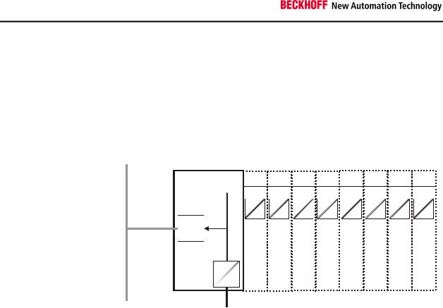
The principle of the Bus Terminal
Bus couplers for various fieldbus systems
BK52x0
DeviceNet |
Power supply |
Potential |
|
Bus Coupler for the |
feed |
Bus end |
|
BK5200 |
Bus Coupler |
terminal |
terminal |
K-Bus |
|
DeviceNet |
|
OVERFL |
|
MS |
|
RUN |
|
BUS OFF |
|
NS |
|
CONNECT |
|
I/O RUN |
|
I/O ERR |
|
BK5200 |
|
Power |
Potential |
contacts |
isolation |
Various Bus Couplers can be used to couple the electronic terminal strip quickly and easily to different fieldbus systems. It is also possible to convert to another fieldbus system at a later time. The Bus Coupler performs all the monitoring and control tasks that are necessary for operation of the connected Bus Terminals. The operation and configuration of the Bus Terminals is carried out exclusively by the Bus Coupler. Fieldbus, K-Bus and I/O level are electrically isolated.
If the exchange of data over the fieldbus fails for a time, counter states are retained, digital outputs are cleared, and analogue outputs take a value that can be separately configured for each output when commissioning.
7
Basic Principles
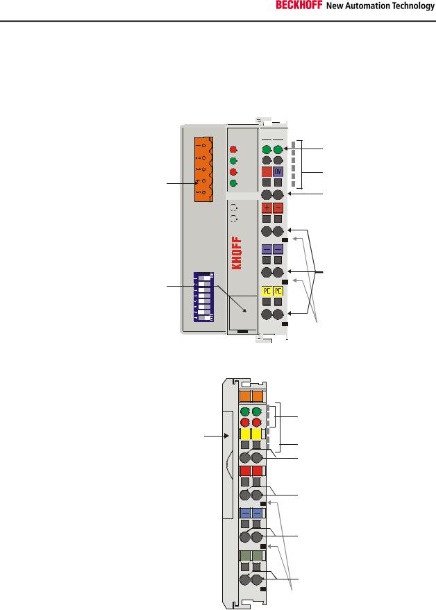
The DeviceNet Coupler
BK5200 / BK5210
The interfaces
A Bus Coupler has six different methods of connection. These interfaces are designed as plug connectors and as spring-loaded terminals.
DeviceNet connector
Configuration-
Interface
DeviceNet
 OVERFL
 MS
MS 
 RUN
RUN
 BUS OFF

NS
 CONNECT

 I/O RUN

 I/O ERR
 BK5200
Power LEDs
Bus Coupler / Power contacts
K-Bus
Power supply Bus Coupler 24 V DC / GND
Input
Power contacts

 Power contacts
The DeviceNet coupler LC5200
BK5200, BK5210:
24 V DC to the topmost terminals “24 V” and “0 V”
The LC5200 Bus Coupler integrates the bus connection into the springloaded terminals.
|
X001 |
002 |
left: |
|
|
|
fieldbus LEDs |
Address |
|
|
right: |
C+ |
C- |
K-Bus LEDs |
|
selector |
|
||
|
|
K-Bus |
|
|
|
|
CAN-H, CAN-L |
|
+ |
+ |
|
|
|
|
V+ |
|
|
|
Power supply for |
|
|
|
Bus Coupler |
|
|
|
and field level |
|
|
|
V- |
|
S |
S |
|
Screen
LC5200 
 Power contacts
Beckhoff
Power supply
The Bus Couplers require a 24 V DC supply for their operation. In the case of the BK52x0 Bus Couplers the connection is made by means of the upper spring-loaded terminals labelled “24 V” and “0 V”. This supply voltage feeds not only the Bus Coupler electronics via the K-Bus, but also the Bus Terminals. In the BK52x0 Bus Couplers the voltage supply for the bus coupler electronics and that of the K-bus are electrically isolated from the field level potentials.
8 |
BK52x0 |

Basic Principles
LC5200:
24V DC to the centre terminal pairs
The LC5200 Bus Coupler is supplied via the two central terminal pairs. The power contacts pass the supply voltage on to the field level.
|
Power contact feed points |
Bottom 3 terminal pairs for The bottom six connections with spring-loaded terminals can be used to |
|
feed |
feed the supply for the peripherals. The spring-loaded terminals are joined |
|
in pairs to a power contact. The feed for the power contacts has no |
|
connection to the voltage supply for the bus coupler (BK52x0). The design |
Maximum 24 V |
of the feed permits voltages of up to 24 V. The assignment in pairs and the |
|
electrical connection between feed terminal contacts allows the connection |
|
wires to be looped through to various terminal points. The current drawn |
Maximum 10 A |
from the power contact must not exceed 10 A for long periods. The current |
|
rating between two spring-loaded terminals is identical to that of the |
|
connecting wires. |
Power contacts
On the right hand face of the Bus Coupler there are three spring contacts Spring contacts on the side for the power contact connections. The spring contacts are hidden in slots so that they can not be accidentally touched. By attaching a Bus Terminal the blade contacts on the left hand side of the Bus Terminal are connected to the spring contacts. The tongue and groove guides on the top and bottom of the Bus Coupler and of the Bus Terminals guarantees that the
power contacts mate securely.
|
Fieldbus connection |
BK5200, BK5210: 5 pin |
The BK52x0 Bus Couplers have a recessed front surface on the left hand |
open style connector |
side. The DeviceNet connection plug can be inserted here. A full |
|
description of the fieldbus interfaces is found elsewhere in this manual. |
LC5200: Bus connection |
In the LC5200 Bus Coupler the bus is connected directly at the upper |
via spring loaded terminals |
terminal pair. |
|
Configuration interface |
Serial interface under the |
The BK52x0 Bus Couplers have an RS232 interface at the bottom of the |
front cover |
front face, whereas on the LC5200 it is located under the cover on the side. |
|
The miniature connector can be joined to a PC with the aid of a connecting |
|
cable and the KS2000 configuration software. The interface allows the |
|
analog channels to be configured and also permits firmware updating. |
|
The functionality of the configuration interface can also be reached via the |
|
fieldbus using the object attributes for the register communication. |
K-Bus contacts
In order to connect the Bus Coupler and Bus Terminals the Bus Coupler 6 contacts on the side has gold contacts on the right hand side. When the Bus Terminals are pushed together the gold contacts automatically make the connection between the Bus Terminals. The voltage supply to the K-Bus electronics in the Bus Terminals and the data exchange between the Bus Coupler and the Bus Terminals is carried out by the K-Bus. A part of the data exchange takes place via a ring structure within the K-Bus. Opening the K-Bus, e.g. by pulling out one of the Bus Terminals, opens the ring. Data exchange is no longer possible. Special mechanisms nevertheless allow the Bus
Coupler to identify the location of the interruption and to report it.
BK52x0 |
9 |
Basic Principles
|
Electrical isolation |
BK5200, BK5210: |
The Bus Couplers operate by means of three independent potential |
3 potential groups: |
groups. The supply voltage feeds the K-Bus electronics in the Bus Coupler |
Fieldbus |
and the K-Bus itself, which are electrically separate. The supply voltage is |
K-Bus |
also used to generate the operating voltage for the fieldbus. |
Peripheral level |
|
|
Remark: All the Bus Terminals are electrically isolated from the K-Bus. The |
|
K-Bus is thus electrically isolated from everything else. |
BK5200, BK5210: Structure of the potential levels in the Bus Terminal system
Bus Coupler |
Bus Terminals |
 K-Bus
K-Bus
Fieldbus 

Periphery level
24 V DC
LC5200: The LC5200 does not provide electrical isolation from the fieldbus and peripheral level. If the peripheral level nevertheless needs to have an electrically isolated implementation, this can easily be achieved through the use of isolating terminals (KL9xxx).
10 |
BK52x0 |
 Loading...