


BC3150 - Bus Terminal Controller for PROFIBUS
Version: 1.1.0
Date: 2006-02-10

Contents
Contents
BC3150 - Bus Terminal Controller for PROFIBUS
1. Foreword |
4 |
Notes on the Documentation |
4 |
Safety Instructions |
5 |
Documentation Issue Status |
6 |
2. Product Overview |
7 |
BCxx50 - Overview |
7 |
The Principle of the Bus Terminal |
8 |
The Beckhoff Bus Terminal System |
9 |
Technical Data |
11 |
Technical Data - BCxx50 |
11 |
Technical Data - PROFIBUS DP |
13 |
Technical Data - PLC |
14 |
3. Mounting and Wiring |
15 |
Mounting |
15 |
Dimensions |
15 |
Installation |
16 |
Wiring |
17 |
Potential Groups, Insulation Testing and PE |
17 |
Power supply |
19 |
Programming cable |
20 |
PROFIBUS Connection |
21 |
PROFIBUS Cabling |
23 |
Fieldbus Components |
1 |

Contents
4. Parameterization and Commissioning |
25 |
Start-up Behavior of the Bus Terminal Controller |
25 |
Setting the slave address |
26 |
Configuration |
27 |
Overview |
27 |
Creating a BX File |
29 |
Downloading a BX Configuration |
30 |
Uploading a BX Configuration |
32 |
Bus Terminal Controller resources |
34 |
ADS via Serial |
36 |
ADS Connection via Serial Interface |
36 |
PROFIBUS |
37 |
PROFIBUS Settings |
37 |
Master Configuration |
38 |
Basic Device File (GSD) |
38 |
Creating a TwinCAT PC File |
39 |
Variable Mapping - PROFIBUS DP |
41 |
BC3150 at 3rd party controller |
42 |
SIEMENS S7 |
42 |
Configuration - Siemens S7 Controller |
42 |
Configuration: Siemens S7 Controller with BX3100 |
43 |
K-Bus |
46 |
K-Bus |
46 |
PLC |
48 |
Inserting a PLC project |
48 |
Measuring the PLC Cycle Time |
49 |
KS2000 |
50 |
KS2000 |
50 |
5. Programming |
51 |
BCxx50 PLC features |
51 |
TwinCAT PLC |
52 |
TwinCAT PLC Error Codes |
53 |
Remanent data |
55 |
Allocated Flags |
56 |
Local process image in delivery state |
57 |
Mapping of the Bus Terminals |
59 |
Local process image in the TwinCAT configuration |
60 |
Creating a boot project |
61 |
Communication between TwinCAT and BX/BCxx50 |
62 |
Upand downloading of programs |
63 |
2 |
Fieldbus Components |

Contents
Libraries |
67 |
Übersicht |
67 |
TcBaseBX |
69 |
System Task Info |
69 |
System Task Info Type |
70 |
System Info |
71 |
System Info Type |
72 |
ADS |
73 |
Local ADS Port Numbers |
73 |
ADS Services |
74 |
BX Debug Function |
75 |
Overview |
75 |
Program Transmission |
76 |
Transmission via Serial Interface |
76 |
Transmission via PROFIBUS |
78 |
Process Image |
80 |
PROFIBUS Process Image |
80 |
6. PROFIBUS |
81 |
System Introduction |
81 |
Fieldbus Overview |
81 |
PROFIBUS DP |
85 |
PROFIBUS DPV1 |
87 |
Cables, Plugs and Switches |
88 |
Topology |
91 |
7. Error handling and diagnosis |
92 |
Diagnostics |
92 |
Diagnostic LEDs |
94 |
8. Appendix |
97 |
First steps with the BC3150 |
97 |
Moving from BC to BX |
99 |
Firmware Update |
102 |
General Operating Conditions |
105 |
Standards for Device Testing |
107 |
Bibliography |
108 |
List of Abbreviations |
109 |
Support and Service |
110 |
Fieldbus Components |
3 |

Notes on the Documentation
1. Foreword
Notes on the Documentation
This description is only intended for the use of trained specialists in control and automation engineering who are familiar with the applicable national standards. It is essential that the following notes and explanations are followed when installing and commissioning these components.
Liability Conditions
The responsible staff must ensure that the application or use of the products described satisfy all the requirements for safety, including all the relevant laws, regulations, guidelines and standards.
The documentation has been prepared with care. The products described are, however, constantly under development. For that reason the documentation is not in every case checked for consistency with performance data, standards or other characteristics. None of the statements of this manual represents a guarantee (Garantie) in the meaning of § 443 BGB of the German Civil Code or a statement about the contractually expected fitness for a particular purpose in the meaning of § 434 par. 1 sentence 1 BGB. In the event that it contains technical or editorial errors, we retain the right to make alterations at any time and without warning. No claims for the modification of products that have already been supplied may be made on the basis of the data, diagrams and descriptions in this documentation.
© This documentation is copyrighted. Any reproduction or third party use of this publication, whether in whole or in part, without the written permission of Beckhoff Automation GmbH, is forbidden.
4 |
Fieldbus Components |
Safety Instructions
Safety Instructions
Safety Rules
The responsible staff must ensure that the application or use of the products described satisfy all the requirements for safety, including all the relevant laws, regulations, guidelines and standards.
State at Delivery
All the components are supplied in particular hardware and software configurations appropriate for the application. Modifications to hardware or software configurations other than those described in the documentation are not permitted, and nullify the liability of Beckhoff Automation GmbH.
Personnel Qualification
This description is only intended for the use of trained specialists in control and automation engineering who are familiar with the applicable national standards.
Description of safety symbols
The following safety symbols are used in this operating manual. They are intended to alert the reader to the associated safety instructions.
This symbol is intended to highlight risks for the life or health of personnel.
Danger
This symbol is intended to highlight risks for equipment, materials or the environment.
Warning
This symbol indicates information that contributes to better understanding.
Note
Fieldbus Components |
5 |

Safety Instructions
Documentation Issue Status
Version Comment
1.1.0Notes to meet the UL requirements added.
1.0.1 |
∙ Chapter Creating a boot project corrected |
∙minor routine corrections (typing errors, orthography etc.)
∙English version available
1.0.0First release (only German version available)
Firmware BC3150
To make a firmware update, you need a serial cable and the KS2000 Configuration Software or the firmware update program.
|
Firmware |
|
|
Comment |
|
|
|
|
|
||
|
|
|
|
|
|
|
0xB0 |
|
Firmware Version 0xB0 |
||
|
|
|
|
|
|
The firmware and hardware version (delivery status) can be found on the label at the bottom of the Bus Terminal Controller.
6 |
Fieldbus Components |

Safety Instructions
2. Product Overview
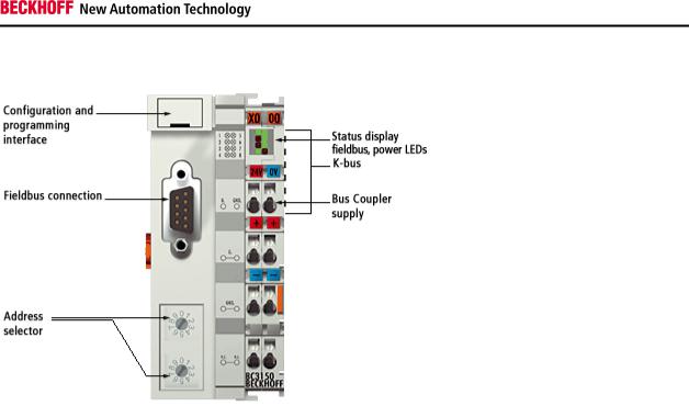
BCxx50 - Overview
Bus Terminal Controllers are Bus Couplers with integrated PLC functionality. The BCxx50 Bus Terminal Controllers have a fieldbus interface, are intelligent slaves and can be used as remote intelligence within the system. They are located in a cost-optimized and compact housing. In contrast to the BCxx00 range, the BCxx50 range supports up to 255 Bus Terminals via the K-Bus extension.
The Bus Terminal Controller is programmed using the TwinCAT programming system according to IEC 61131-3. The BCxx50 configuration/programming interface is used for loading the PLC program. If the TwinCAT software PLC is in use, the PLC program can also be loaded via the fieldbus.
The inputs and outputs of the connected Bus Terminals are assigned in the default setting of the mini-PLC. Each individual Bus Terminal can be configured in such a way that it exchanges data directly through the fieldbus with the higher-level automation device. Similarly, pre-processed data can be exchanged between the Bus Terminal Controller and the higher-level controller via the fieldbus.
Fieldbus interface
The variants of the BCxx50 series Bus Terminal Controllers differ in terms of their fieldbus interfaces. Five different versions cover the main fieldbus systems:
∙BC3150: PROFIBUS DP
∙BC5150: CANopen
∙BC5250: DeviceNet
∙BC8150: RS232 or RS485 (without fieldbus interface)
Programming
The BCxx50 devices are programmed according to the powerful IEC 61131-3 standard. Like for all other BECKHOFF controllers, the TwinCAT automation software is the basis for parameterization and programming. Users therefore have the familiar TwinCAT tools available, e.g. PLC programming interface, System Manager and TwinCAT Scope. Data is exchanged optionally via the serial port (COM1) or via the fieldbus through BECKHOFF PC FCxxxx fieldbus cards.
Configuration
The configuration is also carried out using TwinCAT. The fieldbus interface can be configured and parameterized via the System Manager. The System Manager can read all connected devices and Bus Terminals. After the parameterization, the configuration is saved on the BCxx50 via the serial interface. The configuration thus created can be accessed again later.
Fieldbus Components |
7 |

Safety Instructions
The Principle of the Bus Terminal
8 |
Fieldbus Components |
Safety Instructions
The Beckhoff Bus Terminal System
Up to 64 Bus Terminals each having 2 I/O channels for each signal form
The Bus Terminal system is the universal interface between a fieldbus system and the sensor / actuator level. A unit consists of a Bus Coupler as the head station, and up to 64 electronic series terminals, the last one being an end terminal. For each technical signal form, terminals are available each having two I/O channels, and these can be mixed in any order. All the terminal types have the same mechanical construction, so that difficulties of planning and design are minimized. The height and depth match the dimensions of compact terminal boxes.
Decentralized wiring of each I/O level
Fieldbus technology allows more compact forms of controller to be used. The I/O level does not have to be brought to the controller. The sensors and actuators can be wired decentrally, using minimum cable lengths. The controller can be installed at any location within the plant.
Industrial PCs as controllers
The use of an Industrial PC as the controller means that the operating and observing element can be implemented in the controller’s hardware. The controller can therefore be located at an operating panel, in a control room, or at some similar place. The Bus Terminals form the decentralized input/output level of the controller in the control cabinet and the subsidiary terminal boxes. The power sector of the plant is also controlled over the bus system in addition to the sensor/actuator level. The Bus Terminal replaces the conventional series terminal as the wiring level in the control cabinet. The control cabinet can have smaller dimensions.
Bus Couplers for all usual bus systems
The Beckhoff Bus Terminal system unites the advantages of a bus system with the possibilities of the compact series terminal. Bus Terminals can be driven within all the usual bus systems, thus reducing the controller parts count. The Bus Terminals then behave like conventional connections for that bus system. All the performance features of the particular bus system are supported.
Assembly on standardized C mounting rails
The easy, space-saving, assembly on a standardized C-rail, and the direct wiring of actuators and sensors, without cross-connections between the terminals, standardizes the installation. The consistent labelling scheme also contributes.
The small physical size and the great flexibility of the Bus Terminal system allows it to be used wherever a series terminal is also used. Every type of connection, such as analog, digital, serial or the direct connection of sensors can be implemented.
Modularity
The modular assembly of the terminal strip with Bus Terminals of various functions limits the number of unused channels to a maximum of one per function. The presence of two channels in one terminal is the optimum compromise of unused channels and the cost of each channel. The possibility of electrical isolation through potential feed terminals also helps to keep the number of unused channels low.
Display of the channel state
The integrated LEDs show the state of the channel at a location close to the sensors and actuators.
K-Bus
The K-Bus is the data path within a terminal strip. The K-Bus is led through from the Bus Coupler through all the terminals via six contacts on the terminals’ side walls. The end terminal terminates the K-Bus. The user does not have to learn anything about the function of the K-Bus or about the internal workings of the terminals and the Bus Coupler. Many software tools that can be supplied make project planning, configuration and operation easy.
Fieldbus Components |
9 |

Safety Instructions
Potential feed terminals for isolated groups
The operating voltage is passed on to following terminals via three power contacts. You can divide the terminal strip into arbitrary isolated groups by means of potential feed terminals. The potential feed terminals play no part in the control of the terminals, and can be inserted at any locations within the terminal strip.
Up to 64 terminals can be used within one terminal strip. This count does include potential feed terminals, but not the end terminal.
Bus Couplers for various fieldbus systems
Various Bus Couplers can be used to couple the electronic terminal strip quickly and easily to different fieldbus systems. It is also possible to convert to another fieldbus system at a later time. The bus coupler performs all the monitoring and control tasks that are necessary for operation of the connected Bus Terminals. The operation and configuration of the Bus Terminals is carried out exclusively by the Bus Coupler. Nevertheless, the parameters that have been set are stored in each Bus Terminal, and are retained in the event of voltage drop-out. Fieldbus, K-Bus and I/O level are electrically isolated.
If the exchange of data over the fieldbus is prone to errors or fails for a period of time, register contents (such as counter states) are retained, digital outputs are cleared, and analog outputs take a value that can be configured for each output when commissioning. The default setting for analog outputs is 0 V or 0 mA. Digital outputs return in the inactive state. The timeout periods for the Bus Couplers correspond to the usual settings for the fieldbus system. When converting to a different bus system it is necessary to bear in mind the need to change the timeout periods if the bus cycle time is longer.
The interfaces
A Bus Coupler has six different methods of connection. These interfaces are designed as plug connectors and as spring-loaded terminals.
10 |
Fieldbus Components |

Safety Instructions
Technical Data
Technical Data - BCxx50
|
Technical data |
|
|
|
|
|
|
|
|
|
|
BCxx5x |
|
|
|
|
|
|
|
|
||
|
|
|
|
|
|
|
|
|
|
|
|
|
|
|
|
|
|
|
||||
|
|
|
|
|
|
|
|
|
|
|
|
|
|
|
|
|
|
|
|
|
|
|
|
Processor |
|
|
|
|
|
|
|
|
|
|
16 bit micro-controller |
|
|
|
|
||||||
|
|
|
|
|
|
|
|
|
|
|
|
|
|
|
|
|
|
|
|
|
|
|
|
Diagnostic LEDs |
|
|
|
|
|
|
|
|
|
|
2 x power supply, 2 x K-Bus |
|
|
|
|
||||||
|
|
|
|
|
|
|
|
|
|
|
|
|
|
|
|
|
|
|
|
|
|
|
|
Configuration and programming software |
|
|
|
|
|
|
TwinCAT PLC |
|
|
|
|
||||||||||
|
|
|
|
|
|
|
|
|
|
|
|
|
|
|
|
|
|
|
|
|
|
|
|
|
|
|
|
|
|
|
|
|
|
|
|
|
|
|
|
|
|
|
|
|
|
|
Fieldbus |
|
|
|
|
|
|
|
|
|
|
|
|
|
|
|
|
|
|
|
|
|
|
interface |
|
BC3150 |
|
|
|
BC5150 |
|
BC5250 |
BC8150 |
|
|
- |
|
|
|||||||
|
|
|
|
|
|
|
|
|
|
|
|
|
|
|
|
|
|
|
|
|
|
|
|
Fieldbus |
|
PROFIBUS DP |
|
CANopen |
|
DeviceNet |
- Serial ADS |
- |
|
|
|||||||||||
|
|
|
|
|
|
|
|
|
|
|
|
|
|
|
- KS8000 Protocol |
|
|
|
|
|||
|
|
|
|
|
|
|
|
|
|
|
|
|
|
|
- ModbusRTU |
|
|
|
|
|||
|
|
|
|
|
|
|
|
|
|
|
|
|
|
|
- ModbusASCII |
|
|
|
|
|||
|
|
|
|
|
|
|
|
|
|
|
|
|
|
|
|
|
|
|
|
|
|
|
|
Interfaces |
|
|
|
|
|
|
|
|
|
|
|
|
|
|
|
|
|
|
|
|
|
|
|
|
|
|
|
|
|
|
|
|
|
|
|
|
|
|
|
|
||||
|
Serial interface |
|
COM1 (RS232 for configuration and programming, automatic baud rate detection |
|
|
|
|
|||||||||||||||
|
|
|
9600/19200/38400/57600 baud) |
|
|
|
|
|
|
|
|
|
|
|
|
|||||||
|
|
|
|
|
|
|
|
|
|
|
|
|
|
|
|
|
|
|
|
|
||
|
Terminal Bus (K- |
64 (255 with K-Bus extension) |
|
|
|
|
|
|
|
|
|
|
|
|
||||||||
|
Bus) |
|
|
|
|
|
|
|
|
|
|
|
|
|
|
|
|
|
|
|
|
|
|
|
|
|
|
|
|
|
|
|
|
|
|
|
|
|
|
|
|
|
|
|
|
|
|
|
|
|
|
|
|
|
|
|
|
|
|
|
|
|
|
|
|
|||
|
Technical data |
|
|
BC3150 |
|
|
BC5150 |
|
|
|
BC5250 |
|
|
BC8150 |
|
|
- |
|
|
|||
|
|
|
|
|
|
|
|
|
|
|
|
|
|
|
|
|
|
|
|
|
|
|
|
Digital peripheral signals |
|
2040 inputs/outputs |
|
|
|
|
|
|
|
|
|
|
|
|
|||||||
|
|
|
|
|
|
|
|
|
|
|
|
|
|
|
|
|
||||||
|
Analog peripheral signals |
|
1024 inputs/outputs |
|
|
|
|
|
|
|
|
|
|
|
|
|||||||
|
|
|
|
|
|
|
|
|
|
|
|
|
|
|
|
|
||||||
|
Configuration possibility |
|
via TwinCAT or the controller |
|
|
|
|
|
|
|
|
|
|
|
|
|||||||
|
|
|
|
|
|
|
|
|
|
|
|
|
|
|
|
|
||||||
|
Maximum fieldbus byte |
|
depending on fieldbus |
|
|
|
|
|
|
|
|
|
|
|
|
|||||||
|
number |
|
|
|
|
|
|
|
|
|
|
|
|
|
|
|
|
|
|
|
|
|
|
|
|
|
|
|
|
|
|
|
|||||||||||||
|
Maximum number of bytes |
|
2048 bytes of input data, 2048 bytes of output data |
|
|
|
|
|||||||||||||||
|
- PLC |
|
|
|
|
|
|
|
|
|
|
|
|
|
|
|
|
|
|
|
|
|
|
|
|
|
|
|
|
|
|
|
|
|
|||||||||||
Bus connection |
|
D-sub, 9-pin |
|
Open Style Connector, 5 pin |
|
|
D-sub, 9-pin |
- |
|
|
||||||||||||
|
|
|
|
|
|
|
|
|
|
|||||||||||||
|
Power supply (Us) |
|
|
24 VDC (-15%/+20%) To meet the UL requirements use a 4 A fuse or a power |
|
|
|
|
||||||||||||||
|
|
|
|
|
supply that has to satisfy NEC class 2! |
|
|
|
|
|
|
|
|
|||||||||
|
|
|
|
|
|
|
|
|
|
|
|
|
|
|
|
|
||||||
|
Input current (Us) |
|
|
60 mA + (total K-Bus current)/4 |
|
|
|
|
|
|
|
|
|
|
|
|
||||||
|
|
|
|
|
|
|
|
|
|
|
|
|
||||||||||
|
Starting current |
|
|
approx. 2.5 x continuous current |
|
|
|
|
|
|
|
|
||||||||||
|
|
|
|
|
|
|
|
|
|
|
|
|
|
|
|
|
||||||
|
K-Bus current (5 V) |
|
|
maximum 1000 mA |
|
|
|
|
|
|
|
|
|
|
|
|
||||||
|
|
|
|
|
|
|
|
|
|
|
|
|
|
|
|
|||||||
|
Power contact voltage |
|
maximum 24 VDC |
|
|
|
|
|
|
|
|
|
|
|
|
|||||||
|
(Up) |
|
|
|
|
|
|
|
|
|
|
|
|
|
|
|
|
|
|
|
|
|
|
|
|
|
|
|
|
|
|
|
|
|
|
|
|
|
|||||||
|
Power contact current load |
|
maximum 10 A |
|
|
|
|
|
|
|
|
|
|
|
|
|||||||
|
(Up) |
|
|
|
|
|
|
|
|
|
|
|
|
|
|
|
|
|
|
|
|
|
|
|
|
|
|
|
|
|
|
|
|
|
|
|
|
|
|
|
|
|
|||
|
Recommended fuse (Up) |
|
≤ 10 A |
|
|
|
|
|
|
|
|
|
|
|
|
|
|
|
|
|||
|
|
|
|
|
|
|
|
|
||||||||||||||
|
Dielectric strength |
|
|
500 Vrms (power contact / supply voltage / fieldbus) |
|
|
|
|
||||||||||||||
|
|
|
|
|
|
|
|
|
|
|
|
|
|
|
|
|
|
|
|
|
||
|
Weight |
|
|
approx. 100 g |
|
|
|
|
|
|
|
|
|
|
|
|
|
|
|
|
||
|
|
|
|
|
|
|
|
|
|
|
|
|||||||||||
|
Dimensions (W x H x D) |
|
approx. 44 mm x 100 mm x 68 mm |
|
|
|
|
|
|
|
|
|||||||||||
|
|
|
|
|
|
|
|
|
|
|
|
|
|
|
|
|
|
|
||||
|
Fieldbus Components |
|
|
|
|
|
|
|
|
|
|
|
|
|
|
|
11 |
|||||

Safety Instructions
|
Technical data |
|
|
BC3150 |
|
BC5150 |
|
BC5250 |
|
BC8150 |
|
- |
|
|
|
|
|
|
|
|
|
||||||
|
|
|
|
|
|
|
|
|
|
|
|
|
|
|
Operating temperature |
|
0°C... +55°C |
|
|
|
|
|
|
|
|
||
|
|
|
|
|
|
|
|
|
|
|
|
||
|
Storage temperature |
|
-25°C... +85°C |
|
|
|
|
|
|
|
|
||
|
|
|
|
|
|
|
|
|
|
||||
|
Relative humidity |
|
95 % no condensation |
|
|
|
|
|
|
||||
|
|
|
|
|
|
||||||||
|
Vibration / shock resistance |
|
conforms to EN 60068-2-6 / EN 60068-2-27, EN 60068-2-29 |
|
|
||||||||
|
|
|
|
|
|
|
|
||||||
|
EMC resistance burst / ESD |
|
conforms to EN 61000-6-2 / EN 61000-6-4 |
|
|
|
|
||||||
|
|
|
|
|
|
|
|
|
|
|
|
||
|
Installation pos. |
|
Variable |
|
|
|
|
|
|
|
|
||
|
|
|
|
|
|
|
|
|
|
|
|
||
|
Protection class |
|
IP20 |
|
|
|
|
|
|
|
|
||
|
|
|
|
|
|
|
|
|
|
|
|
|
|
12 |
Fieldbus Components |
Safety Instructions
Technical Data - PROFIBUS DP
|
System data |
|
|
PROFIBUS (BC3150) |
|
|
|
|
|
||
|
|
|
|
||
|
Number of I/O modules |
|
126 (BC3150 max. 99 devices) |
||
|
|
|
|
||
|
Number of I/O points |
|
depending on controller |
||
|
|
|
|
||
|
Data transfer medium |
|
shielded copper cable 2 x 0.25 mm², cable type A according to EN 50170 |
||
|
|
|
|
||
|
Segment length |
|
up to 1200 m |
||
|
|
|
|
||
|
Number of segments |
3 |
|
||
|
|
|
|
||
|
Data transfer rate |
|
up to 12 MBaud |
||
|
|
|
|
||
|
Topology |
|
RS485 line, optical fiber ring |
||
|
|
|
|
||
|
Transmission time |
|
approx. 0.5 ms with 10 stations for 32 bits input/output at 12 MBaud |
||
|
|
|
|
|
|
Fieldbus Components |
13 |
Safety Instructions
Technical Data - PLC
|
PLC data |
|
|
BCxx5x |
|
|
|
|
|
||
|
|
|
|
|
|
|
Programmability |
|
via serial programming interface or via the fieldbus |
||
|
|
|
|
||
|
Program memory |
|
48 kbyte |
||
|
|
|
|
||
|
Source code memory |
|
128 kbyte |
||
|
|
|
|
||
|
Data memory |
|
32 kbyte |
||
|
|
|
|
||
|
Remanent flags |
|
2 kbyte |
||
|
|
|
|
||
|
PLC cycle time |
|
Approx. 3,0 ms for 1000 IL commands (without I/O cycle) |
||
|
|
|
|
||
|
Programming languages |
|
IEC 6-1131-3 (IL, LD, FBD, ST, SFC) |
||
|
|
|
|
||
|
Run time |
|
1 PLC task |
||
|
|
|
|
||
|
Online Change |
|
Yes |
||
|
|
|
|
||
|
Up/Down Load Code |
|
Yes/Yes |
||
|
|
|
|
|
|
14 |
Fieldbus Components |
Safety Instructions
3. Mounting and Wiring
Mounting
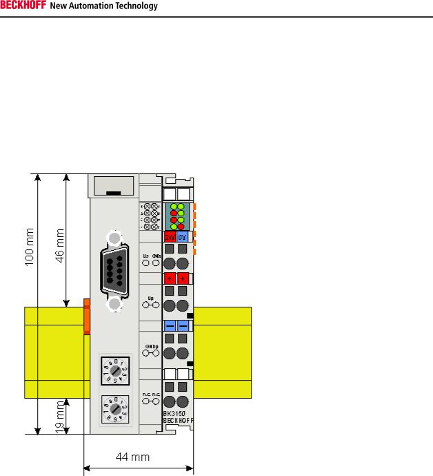
Dimensions
The Beckhoff Bus Terminal system is characterized by low physical volume and high modularity. When planning a project it must be assumed that at least one Bus Coupler and a number of Bus Terminals will be used. The mechanical dimensions of the Bus Couplers are independent of the fieldbus system.
Fig. 1.0 BCxx50
The total width of the fieldbus station is the width of the Bus Coupler/Bus Terminal Controller plus the width of the Bus Terminals being used (incl. KL9010 bus end terminal). Depending on design, the Bus Terminals are 12 or 24 mm wide. The height is 100 mm.
The BCxx50 series Bus Terminal Controllers are 68 mm deep.
Fieldbus Components |
15 |
Safety Instructions
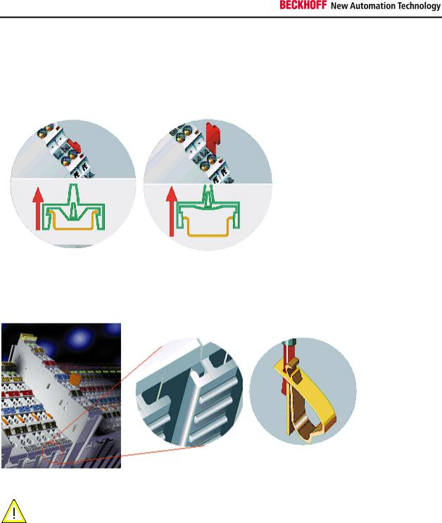
Installation
The Bus Coupler and all the Bus Terminals can be clipped, with a light press, onto a 35 mm mounting rail. A locking mechanism prevents the individual housings from being pulled off again. For removal from the mounting rail the orange colored tension strap releases the latching mechanism, allowing the housing to be pulled off the rail without any force.
Up to 64 Bus Terminals can be attached to the Bus Coupler on the right hand side. When plugging the components together, be sure to assemble the housings with groove and tongue against each other. A properly working connection can not be made by pushing the housings together on the mounting rail. When correctly assembled, no significant gap can be seen between the attached housings.
Insertion and removal of Bus Terminals is only permitted when switched off. The
electronics in the Bus Terminals and in the Bus Coupler are protected to a large measure Warning against damage, but incorrect function and damage cannot be ruled out if they are plugged
in under power.
The right hand part of the Bus Coupler can be compared to a Bus Terminal. Eight connections at the top enable the connection with solid or fine wires from 0.08 mm² to 2.5 mm². The connection is implemented with the aid of a spring device. The spring-loaded terminal is opened with a screwdriver or rod, by exerting gentle pressure in the opening above the terminal. The wire can be inserted into the terminal without any force. The terminal closes automatically when the pressure is released, holding the wire securely and permanently.
16 |
Fieldbus Components |
Safety Instructions
Wiring
Potential Groups, Insulation Testing and PE
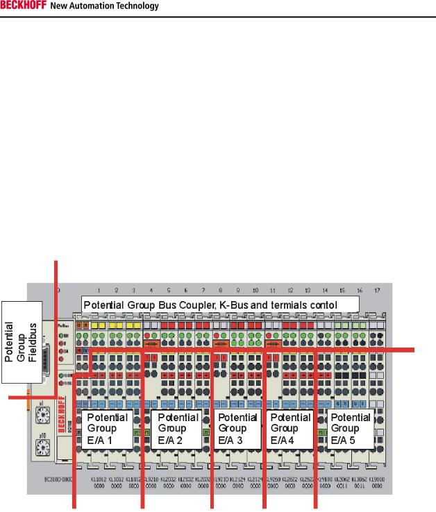
Potential groups
The Beckhoff Bus Terminals stations usually have three different potential groups:
∙The fieldbus interface is electrically isolated (except for individual Low Cost couplers) and forms the first potential group
∙Bus Coupler / Bus Terminal Controller logic, K-Bus and terminal logic form a second galvanically separated potential group
∙The inputs and outputs are supplied via the power contacts and form further potential groups.
Groups of I/O terminals can be consolidated to further potential groups via potential supply terminals or separation terminals.
Insulation testing
The connection between the Bus Coupler / Bus Terminal Controller and the Bus Terminals is automatically realized by pushing the components together. The transfer of the data and the supply voltage for the intelligent electronics in the Bus Terminals is performed by the K-Bus. The supply of the field electronics is performed through the power contacts. Plugging together the power contacts creates a supply rail. Since some Bus Terminals (e.g. analog Bus Terminals or 4-channel digital Bus Terminals) are not looped through these power contacts (or not completely) the Bus Terminal contact assignments must be considered.
The potential feed terminals interrupt the power contacts, and represent the start of a new supply rail. The Bus Coupler / Bus Terminal Controller can also be made use of to feed the power contacts.
Fieldbus Components |
17 |
Safety Instructions
PE power contacts
The power contact labelled PE can be used as a protective earth. For safety reasons this contact mates first when plugging together, and can ground short-circuit currents of up to 125 A.
It should be noted that, for reasons of electromagnetic compatibility, the PE contacts are capacitively coupled to the mounting rail. This can both lead to misleading results and to damaging the terminal during insulation testing (e.g. breakdown of the insulation from a 230 V power consuming device to the PE conductor). The PE conductor to the Bus Coupler / Bus Terminal Controller must be disconnected for the insulation testing. In order to uncouple further feed locations for the purposes of testing, the feed terminals can be pulled at least 10 mm out from the connected group of other terminals. In that case, the PE conductors do not have to be disconnected.
The PE power contact must not be used for other potentials.
18 |
Fieldbus Components |
Safety Instructions
Power supply
Bus Terminal Controller and Bus Terminal supply (Us)
The Bus Terminal Controller requires a supply voltage of 24 VDC for its operation.
The connection is made by means of the upper spring-loaded terminals labelled 24 V and 0 V. This supply voltage feeds the Bus Coupler / Bus Terminal Controller electronics and, over the K-Bus, the electronics of the Bus Terminals. It is electrically separated from the potential of the field level.
UL requirements
 Danger
For the compliance of the UL requirements Us should only be supplied
∙by a 24 VDC supply voltage, supplied by an isolating source and protected by means of a fuse (in accordance with UL248), rated maximum 4 Amp.
∙by a 24 VDC power source, that has to satisfy NEC class 2.
A NEC class 2 power supply shall not be connected in series or parallel with another (class 2) power source!
To meet the UL requirements, Us must not be connected to unlimited power sources!
Danger
Power contacts supply (Up)
The bottom six connections with spring-loaded terminals can be used to feed the supply for the peripherals. The spring-loaded terminals are joined in pairs to a power contact. The feed for the power contacts has no connection to the voltage supply for the BC electronics.
The spring-loaded terminals are designed for wires with cross-sections between 0.08 mm2 and 2.5 mm2.
The assignment in pairs and the electrical connection between feed terminal contacts allows the connection wires to be looped through to various terminal points. The current load from the power contact must not exceed 10 A for long periods. The current carrying capacity between two spring-loaded terminals is identical to that of the connecting wires.
Power contacts
On the right hand face of the Bus Terminal Controller there are three spring contacts for the power contact connections. The spring contacts are hidden in slots so that they can not be accidentally touched. By attaching a Bus Terminal the blade contacts on the left hand side of the Bus Terminal are connected to the spring contacts. The tongue and groove guides on the top and bottom of the Bus Terminal Controllers and of the Bus Terminals guarantees that the power contacts mate securely.
Fieldbus Components |
19 |
Safety Instructions
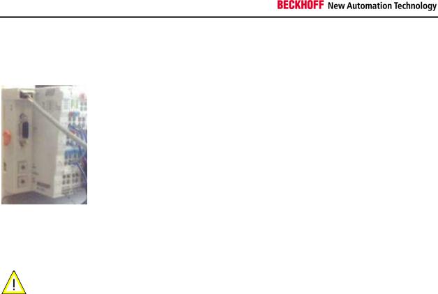
Programming cable
Use the KS2000-Z2 programming cable for serial programming of the Bus Terminal Controller. This cable is included in the scope of supply of the KS2000 software, or it can be ordered separately (order number KS2000-Z2).
KS2000-Z2
The programming cable offers the option of programming the BCxx50 via the serial interface.
|
When the programming cable (between BCxx50 and PC) is connected, the ground |
|
Warning |
connection of the Bus Terminal controller must not be interrupted or disconnected, since |
|
this may destroy the programming cable. |
||
|
20 |
Fieldbus Components |
Safety Instructions
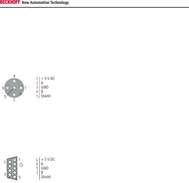
PROFIBUS Connection
M12 circular connector
The M12 socket is inverse coded, and has five pins. Pin 1 is 5 VDC and 3 is GND for the active termination resistor. These must never be misused for other functions, as this can lead to destruction of the device. Pin 2 and pin 4 are the Profibus signals. These must never be swapped over, as this will prevent communication. Pin 5 is the shield, and this is capacitatively coupled to the Fieldbus Box chassis.
M12 socket pin assignment
Nine pole D-Sub
Pin 6 is 5 VDC und Pin 5 is GND for the active termination resistor. These must never be misused for other functions, as this can lead to destruction of the device. Pin 3 and pin 8 are the Profibus signals. These must never be swapped over, as this will prevent communication. Shield is connected to the D-Sub housing that is coupled with lowresistance to the mounting rail.
D-Sub socket pin assignment
Profibus conductor colors
|
Profibus conductors |
|
|
M12 |
|
|
D-Sub |
|
|
|
|
|
|
|
|||
|
|
|
|
|
|
|
|
|
|
B red |
|
Pin 4 |
|
Pin 3 |
|||
|
|
|
|
|
|
|||
|
A green |
|
Pin 2 |
|
Pin 8 |
|||
|
|
|
|
|
|
|
|
|
Fieldbus Components |
21 |
Safety Instructions
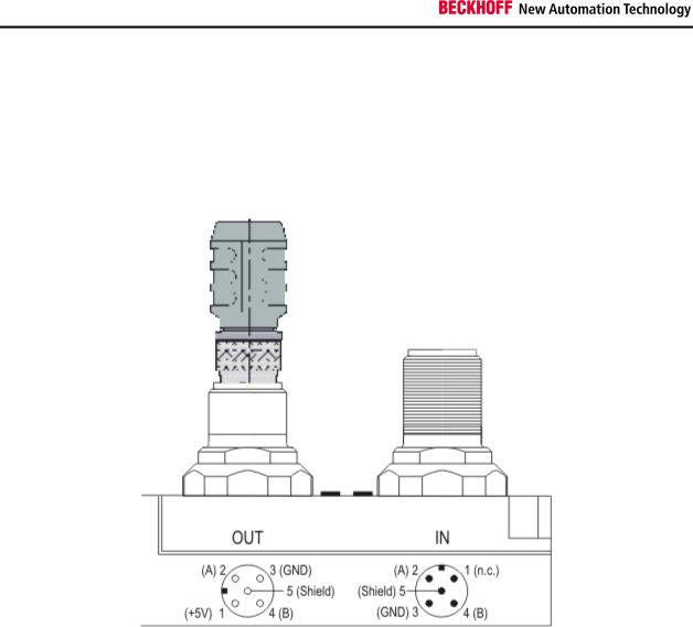
Connection of FieldbusBox modules
The connection of the Fieldbus Box modules is done direct or via a T-piece (or Y-piece).
The B318 series does have a male and female connector, that means no external T-piece is required. The supply voltage (+5VDC) for the termination resistor is only supplied via the female M12 connector. The termination resistor ZS1000-1610 is only available with male connector, therefore the incoming PROFIBUS line should end in a female connector.
Two T-pieces are available:
∙ZS1031-2600 with +5VDC on male and female connector for the termination resistor
∙ZS1031-2610 with +5VDC only on the female connector
22 |
Fieldbus Components |

Safety Instructions
PROFIBUS Cabling
Physical aspects of the data transmission are defined in the Profibus standard (see Profibus layer 1: Physical Layer).
The types of area where a fieldbus system can be used is largely determined by the choice of the transmission medium and the physical bus interface. In addition to the requirements for transmission security, the expense and work involved in acquiring and installing the bus cable is of crucial significance. The Profibus standard therefore allows for a variety of implementations of the transmission technology while retaining a uniform bus protocol.
Cable-based transmission
This version, which accords with the American EIA RS-485 standard, was specified as a basic version for applications in production engineering, building management and drive technology. A twisted copper cable with one pair of conductors is used. Depending on the intended application area (EMC aspects should be considered) the screening may be omitted.
Two types of conductor are available, with differing maximum conductor lengths (see the RS-485 table).
RS485 - Fundamental properties
RS-485 transmission according to the Profibus standard
Network topology |
Linear bus, active bus terminator at both ends, stubs are possible. |
|
|
Medium |
Screened twisted cable, screening may be omitted, depending upon the |
|
environmental conditions (EMC). |
|
|
Number of stations |
32 stations in each segment with no repeater. Can be extended to 127 stations |
|
with repeater |
|
|
Max. bus length without |
100 m at 12 MBit/s |
repeater |
200 m at 1500 KBit/s, up to 1.2 km at 93.75 KBit/s |
|
|
Max. bus length with |
Line amplifiers, or repeaters, can increase the bus length up to 10 km. The |
repeater |
number of repeaters possible is at least 3, and, depending on the manufacturer, |
|
may be up to 10. |
|
|
Transmission speed |
9.6 kBit/s; 19.2 kBit/s; 93.75 kBit/s; 187.5 kBit/s; 500 kBit/s; 1500 kBit/s; 12 MBit/s |
(adjustable in steps) |
|
|
|
Plug connector |
9-pin D-Sub connector for IP20 |
|
M12 round connector for IP65/67 |
|
|
Cabling for Profibus DP and Profibus FMS
Note the special requirements on the data cable for baud rates greater than 1.5 MBaud. The correct cable is a basic requirement for correct operation of the bus system. If a simple 1.5 Mbaud cable is used, reflections and excessive attenuation can lead to some surprising phenomena. It is possible, for instance, for a connected Profibus station not to achieve a connection, but for it to be included again when the neighboring station is disconnected. Or there may be transmission errors when a specific bit pattern is transmitted. The result of this can be that when the equipment is not operating, Profibus works without faults, but that there are apparently random bus errors after start-up. Reducing the baud rate (< 93,75 kBaud) corrects this faulty behavior.
If reducing the baud rate does not correct the error, then in many cases this can indicate a wiring fault. The two data lines maybe crossed over at one or more connectors, or the termination resistors may not be active, or they may be active at the wrong locations.
Installation is made a great deal more straightforward if pre-assembled cables from BECKHOFF are used! Wiring errors are avoided, and commissioning is more rapidly
Note completed. The BECKHOFF range includes fieldbus cables, power supply cables, sensor cables and accessories such as terminating resistors and T-pieces. Connectors and cables for field assembly are nevertheless also available.
Fieldbus Components |
23 |
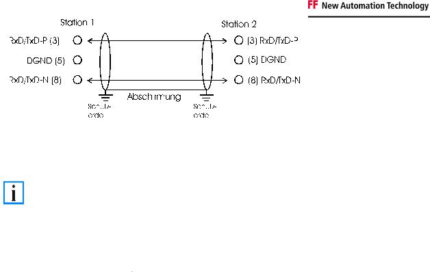
Safety Instructions
|
In systems with more than two stations all devices are wired in parallel. It is essential that |
|
Note |
the bus cables are terminated with resistors at the conductor ends in order to avoid |
|
reflections and associated transmission problems. |
||
|
Distances
The bus cable is specified in EN 50170. This yields the following lengths for a bus segment.
|
Baud rate in kbits/sec |
|
|
9.6 |
|
|
19.2 |
|
|
93.75 |
|
|
187.5 |
|
|
500 |
|
|
1500 |
|
|
12000 |
|
|
|
|
|
|
|
|
|
|
|
|
|
|
|
|
|
||||||||
|
|
|
|
|
|
|
|
|
|
|
|
|
|
|
|
|
|
|
|
|
|
|
|
|
Cable length in m |
1200 |
|
1200 |
|
1200 |
|
1000 |
|
400 |
|
200 |
|
100 |
|
||||||||
|
|
|
|
|
|
|
|
|
|
|
|
|
|
|
|
|
|
|
|
|
|
|
|
Stubs up to 1500 kbaud <6.6 m; at 12 Mbaud stub segments should not be used.
Bus segments
A bus segment consists of at most 32 devices. 126 devices are permitted in a Profibus network. Repeaters are required to refresh the signal in order to achieve this number. Each repeater is counted as one device.
IP-Link is the subsidiary bus system for Fieldbus Boxes, whose topology is a ring structure. There is an IP master in the coupler modules (IP230x-Bxxx or IP230x-Cxxx) to which up to 120 extension modules (IExxxx) may be connected. The distance between two modules may not exceed 5 m. When planning and installing the modules, remember that because of the ring structure the IP-Link master must be connected again to the last module.
Installation guidelines
When assembling the modules and laying the cables, observe the technical guidelines provided by the Profibus User Organization (Profibus Nutzerorganisation e.V.) for Profibus DP/FMS (see www.profibus.com).
Checking the Profibus wiring
A Profibus cable (or a cable segment when using repeaters) can be checked with a few simple resistance measurements. The cable should meanwhile be removed from all stations:
1.Resistance between A and B at the start of the lead: approx. 110 Ohm
2.Resistance between A and B at the end of the lead: approx. 110 Ohm
3.Resistance between A at the start and A at the end of the lead: approx. 0 Ohm
4.Resistance between B at the start and B at the end of the lead: approx. 0 Ohm
5.Resistance between screen at the start and screen at the end of the lead: approx. 0 Ohm
If these measurements are successful, the cable is okay. If, in spite of this, bus malfunctions still occur, this is usually a result of EMC interference. Observe the installation notes from the Profibus User Organization (www.profibus.com).
24 |
Fieldbus Components |
Safety Instructions
4. Parameterization and Commissioning
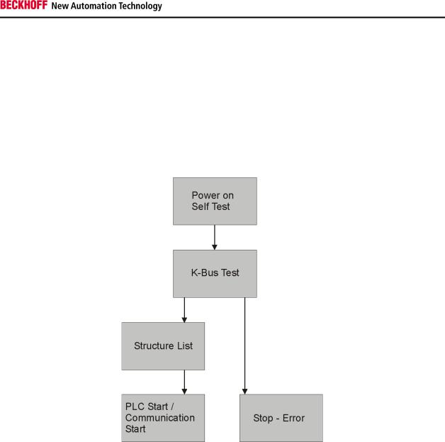
Start-up Behavior of the Bus Terminal Controller
After being switched on, the Bus Terminal Controller checks its state, configures the K-Bus, creates a structure list on the basis of the inserted bus terminals and starts it's local PLC.
The I/O LEDs illuminate and flash as the Bus Coupler starts up. If there are no errors, the I/O LEDs should stop flashing within about 2-3 seconds. In the case of an error, the flash code of the according LED depends on the error type (see Diagnostic LEDs).
Fieldbus Components |
25 |
Safety Instructions
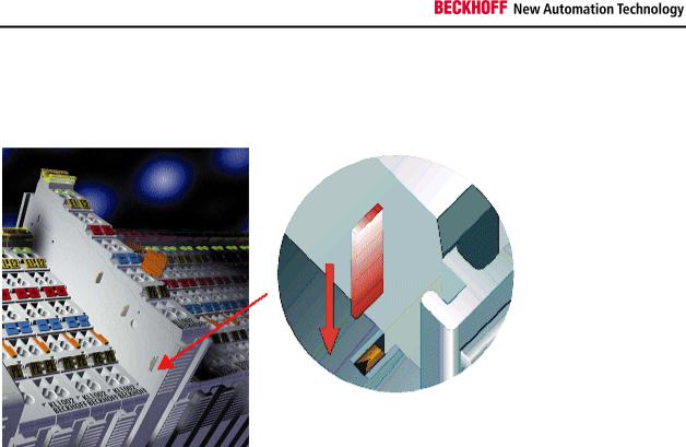
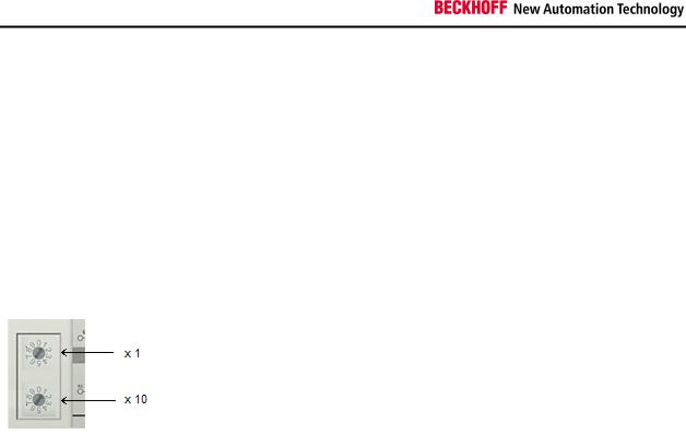
Setting the slave address
The address must be set via the two rotary selection switches. The default setting is 11. All addresses are permitted, although each address may only occur once within the network. For changing an address the Bus Coupler must be switched off. The switches can be set to the required position using a screwdriver. Ensure that the switches engage correctly. The lower switch is the 10-multiplier, the upper switch is the 1-multiplier. The change in address is active as soon as the module is switched on.
Example
You want to set address 34:
∙lower rotary selection switch Sx11: 3
∙upper rotary selection switch Sx10: 4
26 |
Fieldbus Components |

Safety Instructions
Configuration
Overview
Configuration types
DEFAULT-CONFIG
Bus Terminals are mapped in the order they are inserted, i.e. first the complex Bus Terminals followed by the digital Bus Terminals.
The complex Bus Terminals are mapped as follows:
∙Word Alignment
∙complex representation
The fieldbus slave interface are the PLC variables. The PLC variables have addresses from %QB1000 and %IB1000.
TWINCAT-CONFIG
Bus Terminals and PLC variables can be linked freely in TWINCAT-CONFIG (TC-file required). The configuration is transferred to the coupler via the System Manager and ADS.
The following is required for TwinCAT Config:
∙Via the fieldbus (PROFIBUS, CANopen, Ethernet) PROFIBUS: (BC3150, BX3100)
-PC with FC310x from version 2.0 and TwinCAT 2.9 build 1000
-BX3100 with firmware from 0.28 with CIF60 or CP5412
-TwinCAT 2.9 build 946
(WARNING: only one ADS communication is permitted with the Hilscher cards, i.e. either System Manager or PLC Control)
CANopen: (BC5150, BX5100)
PC with FC510x from version 1.76 or higher and TwinCAT 2.9 build 1030 DeviceNet: (BC5250, BX5200)
on request Ethernet: (BX9000):
-TwinCAT 2.10 Build xxxx
∙Via serial ADS TwinCAT 2.9 build 1010 for NT4.0, 2000 or XP
-BX3100 version 1.00
-BX5100 version 1.00
-BX5200 version 1.10
-BX8000 version 1.00
-BC3150, BC5150, BC5250 Frimware B0
-BC8150 TwinCAT 2.10 Build 1244
The BX can be parameterised via the System Manager of the TwinCAT program.
∙Variable I/O mapping
∙Type-specific PROFIBUS data (only BC3150 or BX3100)
∙RTC (Real Time Clock) (only BX-controller)
∙SSB bus (Smart System Bus) (only BX-controller)
∙PLC settings
∙K-Bus settings
The configuration can be transferred to the BXxxxx or BCxx50 via fieldbus ADS protocol or with the serial ADS protocol.
Fieldbus Components |
27 |

Safety Instructions
The TwinCAT configuration can be used to link variables, I/Os and data. The following is possible:
∙PLC - K-BUS
∙PLC - fieldbus (e.g. PROFIBUS slave interface)
∙K-Bus - fieldbus (only the BX-Controller)
In addition, the TwinCAT configuration can be used to parameterise special behaviour, for example whether data are preserved or set to "0" in the event of a fieldbus error.
The real-time clock can be set via a tab in the system manager.
Individual steps
1.Setting the fieldbus address
2.Opening the system manager and creating a TC-file
3.Configuring fieldbus data in the TC-file
4.Saving the TC-file
5.Opening a new system manager, creating a PC file and reading in saved TC-file
6.Creating a link to a PLC task
7.Saving the configuration
8.Starting the TwinCAT system
9.Opening the system manager for the TC-file, completing the configuration and transferring it to the BXxxxx or BCxx50
10.Transferring the program to the BXxxxx or BCxx50
11.Creating a boot project
28 |
Fieldbus Components |
 Loading...