


CP7201-0000
Beckhoff CP7201-0000, CP7202-0000, CP7203-0000, CP7201-0001, CP7202-0001 Installation And Operating Instructions Manual
...
Installation and Operating instructions for
Panel PC CP72xx
Version: 1.2
Date: 2007-10-17


Table of contents
Table of contents
1.
2.
3.
4.
5.
General Notes 3
Notes on the documentation 3
Liability conditions 3
Description of safety symbols 3
Basic safety measures 4
Operator's obligation to exercise diligence 5
Operator requirements 5
Product Description 6
Appropriate Use 6
Structure 6
Access to memory and battery 7
Interfaces 8
Power supply 8
Network connection 8
Additional plug-in cards (optional) 8
Installation Instructions 9
Transport and Unpacking 9
Transport 9
Unpacking 9
Installation of the PC 10
Mounting arm installation 10
Earthing measures 11
Power Supply Connection 12
Connecting Power Supply 12
Cable Cross Sections 12
PC_ON, Power-Status 12
Pin assignment of the power supply connector 13
Pre-assembled cable sets for the power supply 13
Fitting the power supply cable with IP 65 connector 13
Wiring diagram 14
Connecting the Network 15
Pre-assembled network cables 15
Fitting the network cable with IP 65 connector 15
USB-interface (optional) 16
Pre-assembled USB-cables 16
Fitting the USB-cable with IP 65 connector 16
RS232-interface (optional) 17
Pre-assembled serial interface cables 17
Fitting the RS232-interface cable with IP 65 connector 17
Connecting devices 18
Connecting cables 18
Check voltage rating and connect 18
Operating Instructions 19
Switching the Industrial PC on and off 19
First switching on and driver installation 19
Servicing and maintenance 20
Cleaning the Industrial PC 20
Replacing the battery on the motherboard 20
Servicing 20
Shutting down 20
Disposal 20
UPS Software Components (optional) 21
Installation on the PC 21
Help files 21
CP72xx 1

Table of contents
6.
7.
8.
Troubleshooting 22
Fault correction 22
Service and Support 23
Beckhoff's branch offices and representatives 23
Beckhoff headquarters 23
Beckhoff Support 23
Beckhoff Service 23
Assembly dimensions 24
Dimensions and total weight 28
Appendix 29
Technical data 29
Approvals 29
FCC: Federal Communications Commission Radio Frequency Interference
Statement 29
FCC: Canadian Notice 29
2 CP72xx
General Notes
General Notes
Notes on the documentation
This description is only intended for the use of trained specialists in control
and automation engineering who are familiar with the applicable national
standards. It is essential that the following notes and explanations are
followed when installing and commissioning these components.
Liability conditions
The responsible staff must ensure that the application or use of the
products described satisfy all the requirements for safety, including all the
relevant laws, regulations, guidelines and standards.
The documentation has been prepared with care. The products described
are, however, constantly under development. For this reason, the
documentation may not always be have been fully checked for consistency
with the performance data, standards or other characteristics described.
None of the statements in this manual represent a guarantee for as set out
in § 443 of the German Civil Code or a statement about the assumed use
according to the contract as set out in § 434 para. 1 clause 1 no. 1 of the
German Civil Code. In the event that it contains technical or editorial errors,
we retain the right to make alterations at any time and without warning. No
claims for the modification of products that have already been supplied
may be made on the basis of the data, diagrams and descriptions in this
documentation.
© This documentation is protected by copyright. Any reproduction or third
party use of this publication, whether in whole or in part, without the written
permission of Beckhoff Automation GmbH, is forbidden.
Description of safety symbols
The following safety symbols are used in this operating manual. They are
intended to alert the reader to the associated safety instructions.
Danger
This symbol is intended to highlight risks for the life or health of personnel.
Warning
This symbol is intended to highlight risks for equipment, materials or the
environment.
i
Note
This symbol indicates information that contributes to better understanding.
CP72xx 3

General Notes
Basic safety measures
Only switch the PC off after
closing the software
Before the Industrial PC is switched off, software that is running must
be properly closed.
Otherwise it is possible that data on the hard disk is lost. Please read the
section Switching the Industrial PC on and off.
Warning
Switch off all parts of the equipment, then uncouple the fieldbus!
Before opening the housing of the PC, and whenever the PC is being used
for purposes other than plant control, such as during functional tests
following repair, all parts of the equipment must first be switched off, after
which the Industrial PC can be uncoupled from the plant.
Pulling out the fieldbus connection plug uncouples the PC (optional).
Items of equipment that have been switched off must be secured against
being switched on again.
The Industrial PC’s power supply unit must be supplied with
24V
DC
.
Do not exchange any parts when under power!
When components are being fitted or removed, the supply voltage must be
switched off.
Fitting work on the Industrial PC can result in damage:
• If metal objects such as screws or tools fall onto operating circuit
boards.
• If connecting cables internal to the PC are removed or inserted
during operation.
• If plug-in cards are removed or inserted when the PC is switched
on.
4 CP72xx
General Notes
Operator's obligation to exercise diligence
The operator must ensure that
• the Industrial PC is only used for its intended purpose (see Product
Description section);
• the Industrial PC is only operated in a sound condition and in
working order;
• the instruction manual is in good condition and complete, and
always available for reference at the place of installation of the
Industrial PC;
• the Industrial PC is operated, maintained and repaired only by
suitably qualified and authorized personnel.
• the personnel is instructed regularly about relevant occupational
safety and environmental protection aspects, and is familiar with
the operating manual and in particular the safety notes contained
herein.
• none of the safety and warning notes attached to the Industrial PC
are removed, and all notes remain legible.
National regulations
depending on the machine
type
Depending on the type of machine and plant in which the Industrial PC is
used, national regulations governing the controllers of such machines will
apply, and must be observed by the operator. These regulations cover,
amongst other things, the intervals between inspections of the controller.
The operator must initiate such inspections in good time.
Warning
Only trained persons may open the Industrial PC housing!
The operator is responsible for ensuring that only trained electrical staff
opens the housing of the Industrial PC.
Procedure in the event of a
fault
In the event of faults at the Industrial PC, the list in the section
Troubleshooting can be used to determine the measures to be taken.
Operator requirements
Read the operating
instructions
Anyone who uses the Industrial PC must have read these operating
instructions.
Software knowledge Every user must be familiar with all the functions of the software installed
on the Industrial PC to which he has access.
CP72xx 5
Product Description
Product Description
Appropriate Use
The CP72xx add-on PC with 3½” motherboard is designed for mounting
behind a Beckhoff Control Panel. Cooling is achieved via heat sink
structure between the Control Panel and the add-on PC. A fan inside the
closed housing ensures that the heat is distributed evenly.
The Industrial PC is designed for mounting arm installation.
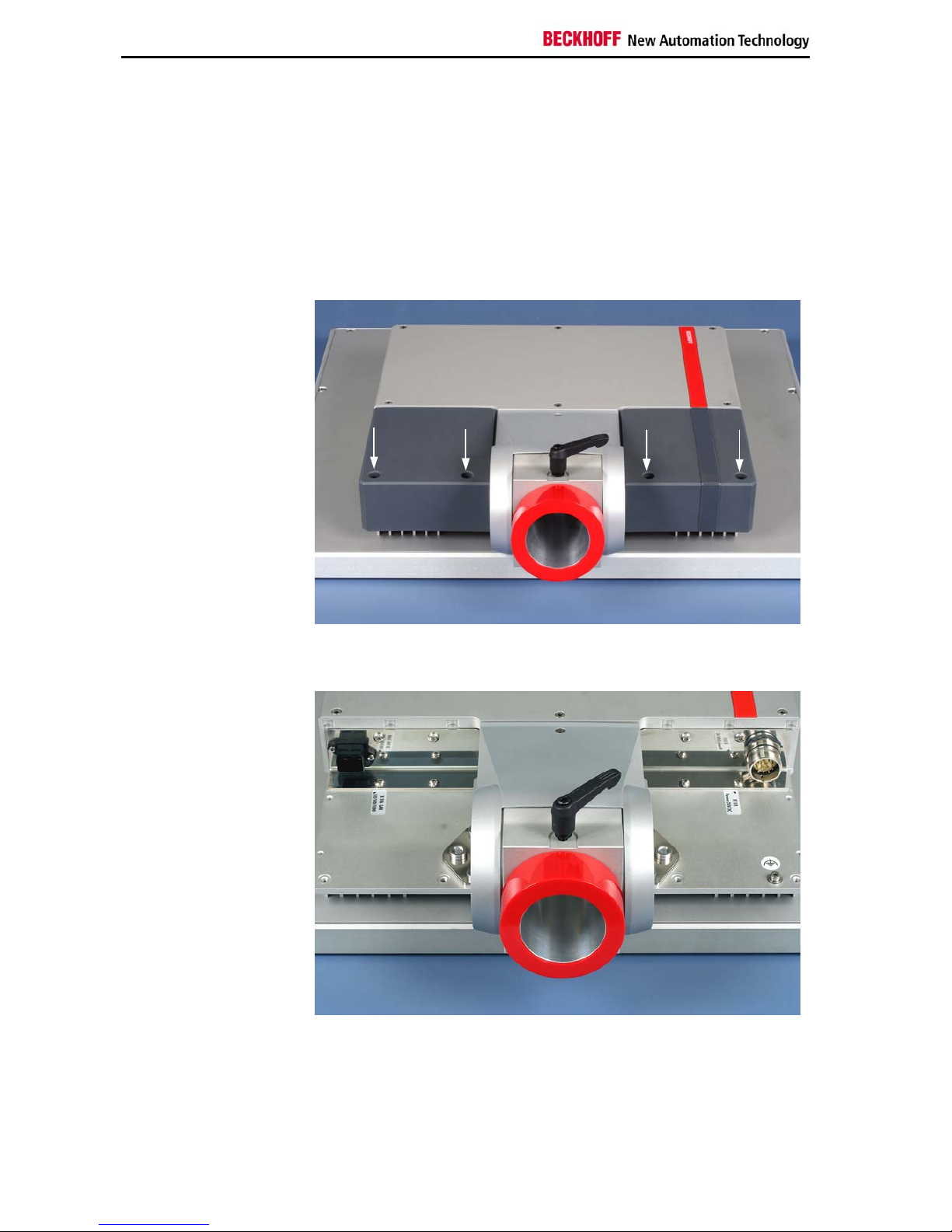
Structure
Rear view of theCP72xx
Access to the connectors
In order to get access to the connectors, first unscrew the according M4cross-head screws (1) (see photo above). The plastic caps (2) can then be
taken off easily.
View to the connectors
The picture shows the view to the connectors when the plastic caps are
removed.
2
1
1
2
1
1
6 CP72xx
Product Description
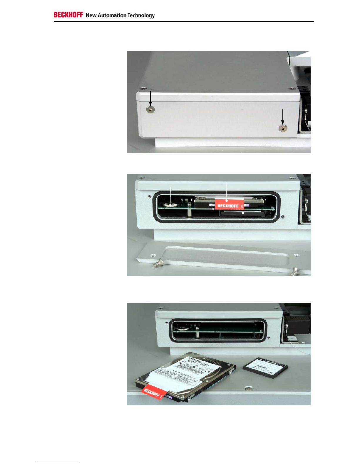
Access to memory and battery
Removing the drive cover
After unscrewing the two Allen screws (see arrows) the drive cover can be
taken off.
View to the hard-disk drive
(optional) and the memory
card
Removing the drive cover allows access to the IDE-hard-disk (1) (optional),
the Compact-Flash-memory card (2) and the lithium battery of the system
clock (3).
Removing the hard-disk
drive and the memory card
The hard-disk drive and the memory card can now be pulled out. Here,
changing the lithium battery is also possible.
The installation takes place in reverse order.
1
3
2
CP72xx 7
Product Description
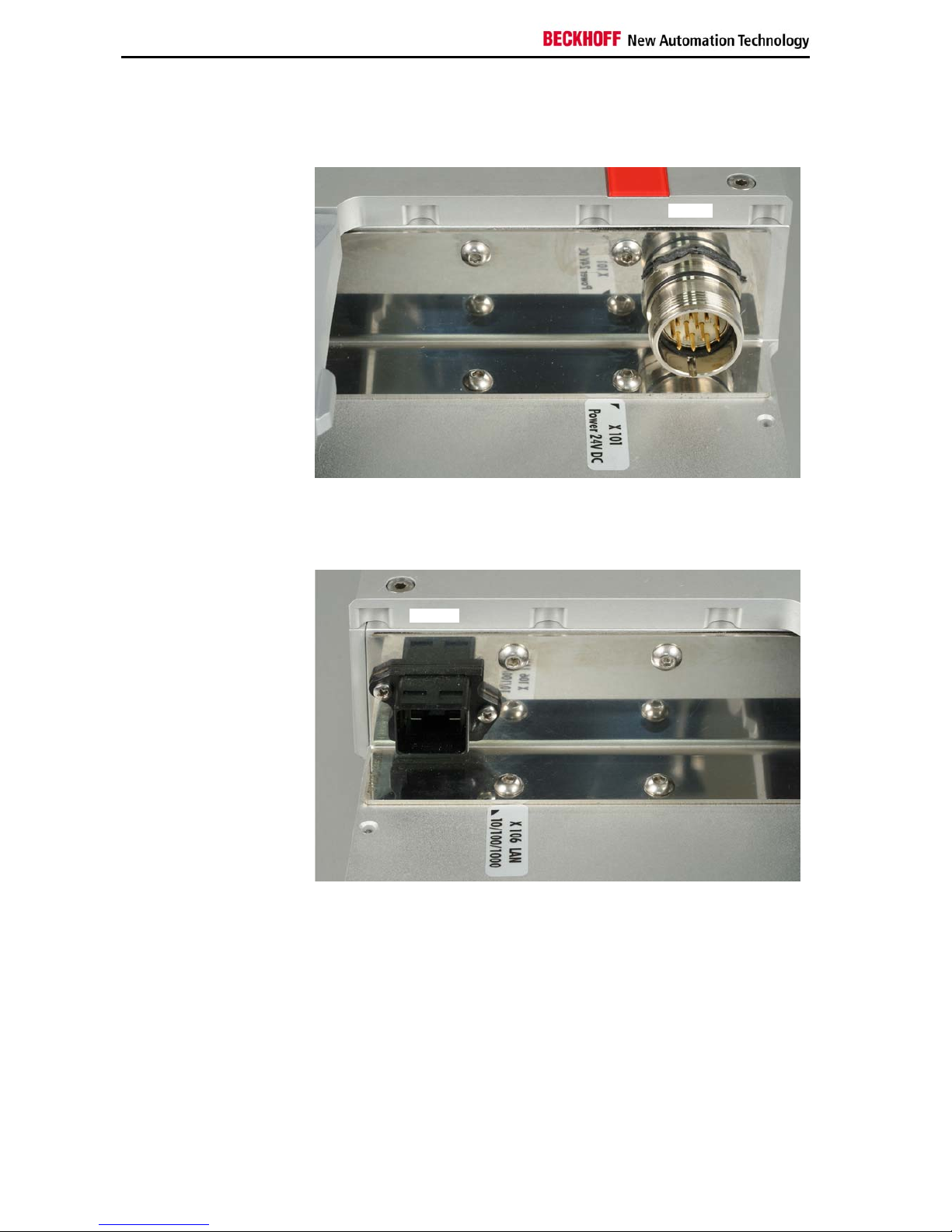
Interfaces
Power supply
Power supply
The power supply connection of the Industrial PC and the connection with
the UPS (optional) is established via the power supply socket (X101).
Network connection
Network connection
The Ethernet-interface with RJ-45-connector (X106) allows the PC to be
connected to a network (LAN). In the basic configuration a Gigabit-port is
available.
X101
X
106
Additional plug-in cards (optional)
Type plate
There are notes at the Industrial PC and in the connection area which
provide information about the hardware configuration of the Industrial PC at
the time it was supplied.
8 CP72xx
 Loading...