


Documentation for
Power supply units and I/O interfaces for CX Embedded PC Systems
CX1100-0001
CX1100-0002 (K-bus)
CX1100-0003 (IP Link und K-bus)
CX1100-0004 (E-bus)
version: 1.9 date: 2007-03-06

Table of Contents
Table of Contents
1. Foreword |
|
Notes on the Documentation |
3 |
Safety Instructions |
4 |
Documentation issue status |
5 |
2. Product overview |
6 |
Appropriate use |
6 |
System overview |
7 |
Architecture |
11 |
Memory mapping |
13 |
Display |
14 |
Technical data |
14 |
Operating the display |
15 |
Operating the display via ADS codes |
19 |
4 + 1 navigation switch |
20 |
Operating the switch |
20 |
CX1100-0001 |
23 |
Overview |
23 |
Techical data |
24 |
CX1100-0001 architecture |
25 |
CX1100-0002 |
26 |
Overview |
26 |
Techical data |
27 |
CX1100-0002 (K-Bus) architecture |
30 |
CX1100-0003 |
32 |
Overview |
32 |
Techical data |
33 |
CX1100-0003 (IP-Link Bus) architecture |
36 |
CX1100-0004 |
38 |
Overview |
38 |
Techical data |
39 |
CX1100-0004 (E-Bus) architekture |
40 |
3. |
Transport |
41 |
|
Unpacking, installation and transport |
41 |
4. |
Fitting and wiring |
42 |
|
Mechanical assembly |
42 |
|
Dimensions |
42 |
|
Mechanical installation |
44 |
Embedded PC |
1 |
|

Table of Contents
|
Commissioning |
46 |
|
Electrical connection |
46 |
5. |
Error handling and diagnostics |
48 |
|
Bus diagnosis in PLC |
48 |
|
LED CX1100-0001 |
52 |
|
LED CX1100-0002 |
53 |
|
LED CX1100-0003 |
55 |
|
LED CX1100-0004 |
58 |
6. |
Decommissioning |
59 |
|
Removal and Disposal |
59 |
7. |
Appendix |
61 |
|
ADS errorcodes |
61 |
|
Certifications |
63 |
|
Support |
64 |
2 |
Embedded PC |

Foreword
1. Foreword
Notes on the Documentation
This description is only intended for the use of trained specialists in control and automation engineering who are familiar with the applicable national standards. It is essential that the following notes and explanations are followed when installing and commissioning these components.
Liability Conditions
The responsible staff must ensure that the application or use of the products described satisfy all the requirements for safety, including all the relevant laws, regulations, guidelines and standards.
The documentation has been prepared with care. The products described are, however, constantly under development. For that reason the documentation is not in every case checked for consistency with performance data, standards or other characteristics. None of the statements of this manual represents a guarantee (Garantie) in the meaning of § 443 BGB of the German Civil Code or a statement about the contractually expected fitness for a particular purpose in the meaning of § 434 par. 1 sentence 1 BGB. In the event that it contains technical or editorial errors, we retain the right to make alterations at any time and without warning. No claims for the modification of products that have already been supplied may be made on the basis of the data, diagrams and descriptions in this documentation.
© This documentation is copyrighted. Any reproduction or third party use of this publication, whether in whole or in part, without the written permission of Beckhoff Automation GmbH, is forbidden.
Embedded PC |
3 |
Foreword
Safety Instructions
Safety Rules
The responsible staff must ensure that the application or use of the products described satisfy all the requirements for safety, including all the relevant laws, regulations, guidelines and standards.
State at Delivery
All the components are supplied in particular hardware and software configurations appropriate for the application. Modifications to hardware or software configurations other than those described in the documentation are not permitted, and nullify the liability of Beckhoff Automation GmbH.
Personnel Qualification
This description is only intended for the use of trained specialists in control and automation engineering who are familiar with the applicable national standards.
Description of safety symbols
The following safety symbols are used in this operating manual. They are intended to alert the reader to the associated safety instructions.
Danger
This symbol is intended to highlight risks for the life or health of personnel.
Warning
This symbol is intended to highlight risks for equipment, materials or the environment.
Note
This symbol indicates information that contributes to better understanding.
4 |
Embedded PC |
Foreword
Documentation Issue Status
|
Version |
|
|
Changes |
|
|
|
|
|
||
|
|
|
|
|
|
1.9 |
|
|
Notes on wire installation added |
||
|
|
|
|
||
1.8 |
|
|
Notes on terminal bus diagnosis with firmware > B7 added |
||
|
|
|
|
||
1.7 |
|
|
Terminal bus diagnosis in PLC program added |
||
1.6 |
|
|
Notes on hardware revision added |
||
|
|
|
|
||
1.5 |
|
|
Blink codes for IP-Link errors added |
||
1.4 |
|
|
Display control via ADS commands added |
||
|
|
|
|
||
1.3 |
|
|
Changes in GCB – Watchdog Error Counter |
||
|
|
|
|
||
1.2 |
|
|
Blink codes for CX1100-0004 (EtherCAT) extended |
||
1.1 |
|
|
library for 4 + 1 navigation switch added |
||
|
|
|
|
||
1.0 |
|
|
memory mapping / fieldbus connections |
||
0.2 |
|
|
revised version |
||
|
|
|
|
description of four power supplies |
|
|
|
|
|
CX10xx architecture description |
|
0.1 |
|
|
preliminarily version |
||
Embedded PC |
5 |

Product overview
2. Product overview
Appropriate Use
The CX1020 device series is a modular control system designed for DIN rail installation. The system is scalable, so that the required modules can be assembled and installed in the control cabinet or terminal box as required.
6 |
Embedded PC |
Product overview
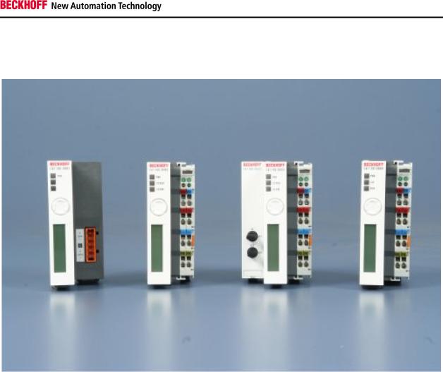
CX1100-000x
power supply units and I/O interfaces
One of four power supply modules can be selected for a CX10x0 system. The power supply of all other system components is ensured via the internal PC104 bus; no separate supply lines are required. However, the CX1100 components offer further important characteristics that go beyond a pure power supply: an integrated NOVRAM enables the fail-safe storage of process data, an LCD display with two lines of 16 characters each is used for displaying system and user messages. Local I/O signals are connected via the CX1100-0002 power supply variant, to which all Beckhoff Bus Terminals can be connected, or via CX1100-0003, which in addition to the Bus Terminals enables the connection of Extension Box IExxxx type Beckhoff Fieldbus Box modules. The option to connect Bus Terminals or Fieldbus Box modules creates a control system with a very variable, expandable I/O level with large signal variety. The I/O data are stored in a DPRAM, which is accessible by the CPU via the system bus. The power supplies of the CX system can be changed in the field: If, for example, local I/O via Bus Terminals is required, CX1100-0001 can be replaced with CX1100-0002 in the field. Local I/O signals are connected via the CX1020 and the CX1100-0002 power supply variants (Bus Terminals), CX1100-0003 (Bus Terminals
and Fieldbus Box modules via IP-Link) or CX1100-0004 for EtherCAT Terminals. With CX1100-0004 the I/O data are stored directly in the main memory of the CPU; a DPRAM is no longer required. The CX1100-0004 power supply unit for EtherCAT Terminals can only be connected in conjunction with the basic CX1020 CPU module.
The technical data are as follows:
CX1100-0001
CX1100-0002
CX1100-0003
CX1100-0004
An overview about architecture with the common system components GCB, ACB, NOVRAM, Display und Taster are described together in one chapter. Special interfaces are described in the power supply units containing the
Embedded PC |
7 |
Product overview
interfaces.
Architecture
Display
Taster
Architecture of the power supply units
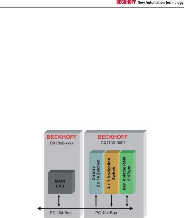
The four power supply units for the CX10x0-System accomplish more task than supporting the system with power. Each module has three basic functions. Additional each model supports different connection to communication busses. Caused by these different connections the internal architecture differ. At first the common functions are described.
All power supply feature, except for power supply, the following functions:
1.Display 2 x 16 characters
2.4+1 navigation switch
3.Non Volatile RAM
These functions are managed by the control program via the PC104 bus. The structure of the CX1100-0001 is shown in the following figure:
"General Control Block" (GCB)
The top 16 byte of the system control area (starting at the physical hex address D0000 + Offset FF0) form the general control block GCB, which holds the control byte required to start the I/O processing of the K-Bus and IP-Link.
The CPU of the main module controls the whole architecture. With memory mapped I/O regions data can be exchanged. The data needed to run the system is combined in the "General Control Block" (GCB). Its base address is "0xD1000". The figure shows the Data and the offset. Some registers are not needed in all units. So only the requested registers are mapped other addresses are masked out.
8 |
Embedded PC |
Product overview
Firmware Version:
These two bytes contain the hex decimally coded version number of the CX1100 firmware. E.g. the first byte could show B3(hex): this results in firmware version B3.
Firmware Revision:
These two bytes contain the hex decimally coded revision number of the CX1100 firmware. E.g. the byte could show 00: this results in revision 00.
Service Request / Response Bitfield: (nur für CX1100-0002 / -0003)
These two bytes contain a sequence of bits, by which certain service functions may be executed. The service function is invoked by setting the appropriate request bit, the controller executes and sets the response bit. Before the same function can be invoked again, the request bit must be set to zero and wait until the response bit is also set to zero. An execution error is signaled by raising response bit 7.
|
Bitfeld |
|
|
Bit |
7 |
|
|
Bit 6 |
|
|
Bit 5 |
|
|
Bit 4 |
|
|
Bit 3 |
|
|
Bit 2 |
|
|
Bit |
1 |
|
|
Bit 0 |
|
|
|
|
|
|
|
|
|
|
|
|
|
|
|
|
|
|
|
|||||||||||
|
|
|
|
|
|
|
|
|
|
|
|
|
|
|
|
|
|
|
|
|
|
|
|
|
|
|
|
|
|
Request |
- |
|
|
- |
|
- |
|
- |
|
- |
|
|
Link Images |
|
Remap |
|
|
|
Reset Node |
||||||||
|
|
|
|
|
|
|
|
|
|
|
|
|
|
|
|
|
|
|||||||||||
|
Response |
|
Error |
- |
|
- |
|
- |
|
- |
|
|
Images Linked |
|
Remapped |
|
Reset Done |
|||||||||||
|
|
|
|
|
|
|
|
|
|
|
|
|
|
|
|
|
|
|
|
|
|
|
|
|
|
|
|
|
Reset Node:
with this bit, a software reset of the 80C165 microcontroller can be performed. This is different from the hardware reset which may be performed in the Auxiliary Control Block (ACB).
Remap:
with this bit, the two-byte PLC interfaces normally residing in the input/output process areas can be remapped into the general control block for K-Bus and IP-Link. Thus the input/output process image areas can be kept clean and for the sole purpose of storing I/O-data.
Link Images:
if set, this bit links the K-Bus logically to the IP-Link in the case of error occurrence - meaning that if one of them stops operating, the other one is stopped as well. By default, this bit is set so stopping both I/O systems in case of error is the standard behavior.
Watchdog Time:
With the request of an I/O cycle through "PD cycle request", a watchdog timer with this specified millisecond time ist started. If the cycle is not being restarted by a next "PD cycle request", the watchdog elapses and as a consequence the output process image is zeroed. This resets all outputs to a safe state (OFF). If another value than the default 100ms is written to this cell, a "Reset node" is needed to activate the change.
Embedded PC |
9 |
Product overview
Cycle Time:
This is the time elapsed between the initiation and termination of an I/O process image update (K-Bus + IP-Link ). The time is recorded in units of microseconds and starts with writing a new cycle request to the field "PD cycle request" and it stops with the termination response in the field "PD cycle ready". For CX1100-0002 this time reflects the K-Bus update time, for CX1100-0003 it is the sum of K-Bus update time and IP-Link update time.
Watchdog Error Counter:
If the Watchdog Time exceeds the value in this register is increased by one. In this way the user can get the numbers of watchdog-time errors. (available since firmware revision B6)
Processdata Error:
This byte contains the information on the error status of the I/O blocks. The possible bit codes are:
|
Bitfeld |
|
|
Bit |
7 |
|
|
Bit |
6 |
|
|
Bit |
5 |
|
|
Bit |
4 |
|
|
Bit |
3 |
|
|
Bit |
2 |
|
|
Bit 1 |
|
|
Bit 0 |
|
|
|
|
|
|
|
|
|
|
|
|
|
|
|
|
|
|
|
|||||||||||||||
|
|
|
|
|
|
|
|
|
|
|
|
|
|
|
|
|
|
|
|
|
|
|
|
|
|
|
|
|
|
|
|
|
|
Processdata Error |
- |
|
|
- |
|
|
- |
|
|
- |
|
|
- |
|
|
- |
|
|
|
IP-Link Error |
|
K-Bus Error |
|||||||||
|
|
|
|
|
|
|
|
|
|
|
|
|
|
|
|
|
|
|
|
|
|
|
|
|
|
|
|
|
|
|
|
|
The bit is set to "TRUE", if an error occurred. If both bits are zero, there is no error on either bus system. Error recovery may be attempted by invoking the "Reset bus" service in the corresponding CB of either K-Bus or IP-Link.
Processdata Cycle Overrun:
This byte contains a counter, which is incremented each time a new process data cycle is requested although the previous cycle has not yet completed. This can happen only due to a handshake programming error or if the user task cycle time is shorter than the time for I/O update.
PD Cycle Ready / PD Cycle Request:
These two bytes contain the request value and the ready value for operating a process data (PD) I/O cycle. The user program is supposed to write a pattern (e.g. an up-counter value ) to the request byte, thus triggering the I/O cycle. Once the I/O cycle is finished, the microcontroller will set the ready byte to match the request byte. A new request can then be written to the request byte.
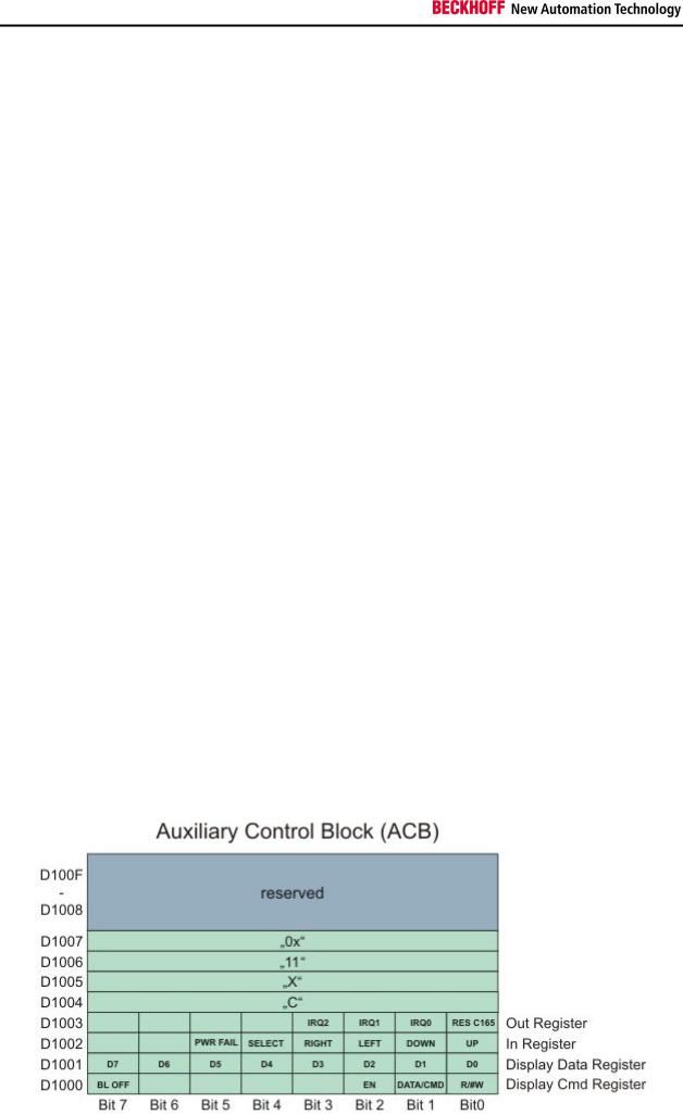
"Auxiliary Control Block" (ACB)
The Auxiliary Control Block of CX1100 is a block of 16 bytes and starts at address D1000 (hex). It is a miscellaneous control block for controlling:
-the 2x16char FSTN LCD Display
-the navigation switch
-the hardware reset of the 80C165 microcontroller
The following schematic shows the layout of the ACB and is followed by a description of the single bits contained in it.
10 |
Embedded PC |

Product overview
Display Cmd Register:
Bit 0 R/#W
Bit 1 DATA/#CMD
Bit 2 EN
Bit 7 BL OFF
R/#W: This bit control the Read or Write operation for programming the display2x16 char LCD display.
DATA/#CMD: This bit controls whether the byte "Display Data Reg" holds a command or display data.
EN: This is the enable bit for executing the operation with the display controller.
BL OFF: If set, this bit turns of the backlight of the LCD Display. This feature may be used for blinking with the backlight, thus attracting the users attention to an important message on the display. It may also be
used to save power in the case of power loss and UPS operation.
Display Data Register:
These are the data bits for issuing commands or reading/writing data to the display controller. These bits are operated in conjunction with bits 0,1,2 of the Display Cmd Reg. For more detailed information please refer to the display controller documentation.
In Register:
These bits reflect the contact status of the 4+1 direction navigation switch on the front side of the CX1100 unit. These events may be used by a software for implementing a menu driven data input/output together with the LCD display.
Bit 0 UP
Bit 1 DOWN
Bit 2 LEFT
Bit 3 RIGHT
Bit 4 SELECT
Bit 5 PWR-FAIL (reserved for future use - do not use)
An example for access the switch is given in the detailed description of the switch.
Out Register:
Bit 0 RES C165
This bit resets the microcontroller 80C165 and restarts the initialization of the K-Bus and IP-Link circuit. For doing the reset, this bit must be set high and then set back to low. There is no need for an explicit hold time.
This bit may be used to recover from K-Bus faults such as removing a terminal during operation. It needs to be set at least once at startup or initialization of the user software before operating the k-Bus.
Bit 1 IRQ0 (reserved for future use - do not enable)
Bit 2 IRQ1 (reserved for future use - do not enable)
Bit 3 IRQ2 (reserved for future use - do not enable)
Memory region 0xD1004 to 0xD1008:
In this region the type of the power supply module is encoded. By adding the four registers the type description is given:
CX1101 CX1100-0001 power supply unit with display, 4 + 1 navigation switch and NOVRam
CX1102 CX1100-0002 power supply unit with display, 4 + 1 navigation switch, NOVRam and K-bus connection
CX1103 CX1100-0003 power supply unit with display, 4 + 1 navigation switch, NOVRam, K-bus-connection and IP-Link-connection
CX1104 CX1100-0004 power supply unit with display, 4 + 1 navigation switch, NOVRam and E-bus connectio.
Das Non Volatile RAM
The NOVRAM is one of the most important functions of the power supply unit. The access is realized via the PC104 bus. The mapping to PLC is realized by TwinCAT System Manager. Here needed variables can be defined and mapped to memory. Further details are given in the TwinCAT documentation.
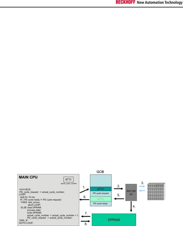
K-BUS and IP-LINK Operation
This section describes how to trigger the K-Bus (and in the case of CX1100-0003 also the I/O-boxes connected to IP-
Embedded PC |
11 |
Product overview
Link) in order to read input values and write output values. The procedure is the same for IP-Link, the description limits itself to K-Bus for textual simplicity.
The I/O operation is done through the bytes named "PD cycle ready" and "PD cycle request" in the GCB. The K-Bus cycle is triggered by a write operation to the byte "PD cycle request". Although the value being written to this byte does not matter (it is only the write operation which is important), it is recommendable write a counter-up value to this byte. The microcontroller for the K-Bus will react to the write operation by performing a K-Bus cycle and gathering the I/O data. Once the cycle is completed and the electrical signal input data are written to the DP-RAM, the microcontroller will set the content of byte "PD cycle ready" equal to the content of "PD cycle request", thus signaling the completion of the I/O cycle. The time required to run a K-Bus cycle depends on the number of terminals attached to CX1100: it is minimum 700 microseconds and typically well below 5 milliseconds. The K-Bus cycle time can be viewed by using the TwinCAT System Manager tool, by entering the exact terminal configuration.
At startup of the user program, before going into cyclic operation, it is mandatory to reset the K-Bus controller by triggering the "RES C165" bit in the Auxiliary Control Block section of CX1100. Please refer to the description of the ACB for how to do this.
The sequence of operating the K-Bus can be explained by assuming a cyclic automation task executed each 10 ms on the main CX1000 CPU:
Task cycle "n":
-check if K-Bus operation of previous cycle has finished: is "PD cycle ready" = "PD cycle request" ? Proceed if yes, issue error message and abort cyclic task operation if not, because a K-Bus cycle does not need 10 milliseconds to finish !
-read the input data from the DP-RAM (these are the input data gathered by the previous cycle "n-1" )
-write the output data to the DP-RAM (these are the outputs calculated by the previous cycle "n-1" ).
-increment and write the new value to "PD cycle request"
-perform task user code
Task cycle "n+1":
-check if K-Bus operation of previous cycle has finished: is "PD cycle ready" = "PD cycle request" ? Proceed if yes, issue error message and abort cyclic task operation if not, because a K-Bus cycle does not need 10 milliseconds to finish !
-read the input data from the DP-RAM (these are the input data gathered by the previous cycle "n" )
-write the output data to the DP-RAM (these are the outputs calculated by the previous cycle "n" ).
-increment and write the new value to "PD cycle request"
-perform task user code
Of course only the I/O bytes needed should be copied to or from the DP-RAM, since each read or write operation over PC104 is time consuming. Please note that the terminal outputs need a K-Bus refresh no later than 100 milliseconds, otherwise the watchdog in each terminal will shut off the outputs. This means that the task cycle time should be below 100 milliseconds. Also, if more than one cyclic automation task needs access to K-Bus I/O, it is important that only one task operates the K-Bus and the other tasks implement an I/O buffering in order to have a consistent I/O image. In this scenario, the task with the highest priority has the shortest cycle time and will trigger the K-Bus.
Please note also that it is assumed that in each cycle the integrity of the K-Bus is being checked by examining the "Processdata error" field in the GCB. Cyclic operation should be aborted in the case of an I/O error and user should be prompted for corrective actions. Cyclic operation can be resumed after resetting the faulty bus over the service request fields of the control block.
12 |
Embedded PC |
Product overview
Adapter RAM Hardware address overview
available memory addresses CX1020: D0000-DFFFF (hex)
|
Base Address |
|
|
End Address |
|
|
|
Access |
|
|
|
|
|
|
|
|
|
|
|||
|
(hex) |
|
|
(hex) |
|
Size(Bytes)(hex) |
|
Type |
|
Description |
|
|
|
|
|
|
|
|
|
|
|
|
D0000 |
|
D0FFF |
1000 |
|
R/W |
CX1100-0002/3 Dual Ported RAM |
|||
|
|
|
|
|
|
|
|
|||
|
D1000 |
|
D100F |
10 |
|
R/W |
CX1100 Auxiliary Control Block( LCD |
|||
|
|
|
|
|
|
|
|
|
|
Display, misc. registers) |
|
D1010 |
|
D101F |
10 |
|
R/W |
CX1100-0900 UPS Control Block |
|||
|
|
|
|
|
|
|
|
|||
|
D2000 |
|
D3FFF |
2000 |
|
R/W |
CX1100 Non Volatile RAM |
|||
|
|
|
|
|
|
|
|
|||
|
D4000 |
|
D5FFF |
2000 |
|
R/W |
CX1500-M310 Profibus Master DPRAM |
|||
|
D6000 |
|
D7FFF |
2000 |
|
R/W |
CX1500-M510 CANopen Master |
|||
|
|
|
|
|
|
|
|
|
|
DPRAM |
|
D8000 |
|
D9FFF |
2000 |
|
R/W |
CX1500-M520 DeviceNet Master |
|||
|
|
|
|
|
|
|
|
|
|
DPRAM |
|
DA000 |
|
DBFFF |
2000 |
|
R/W |
CX1500-M200 Lightbus Master DPRAM |
|||
|
|
|
|
|
|
|
|
|||
|
DC000 |
|
DDFFF |
2000 |
|
R/W |
CX1500-M750 Sercos Master DPRAM |
|||
For some fieldbus connections (all Slave modules) the base addresses are mapped in the memory region upper DFFFF(hex). So this modules must be ordered with other base addresses. The same situation takes place if more than two or more master modules of same type are used (for more see note below). The order numbers for the modules are:
order number |
alternative ISA-Adresse |
Master connection |
|
|
|
CX1500-Mxxx-0001 |
D4000 |
|
|
CX1500-Mxxx-0002 |
D6000 |
|
|
CX1500-Mxxx-0003 |
D8000 |
|
|
CX1500-Mxxx-0004 |
DA000 |
CX1500-Mxxx-0005 |
DC000 |
|
|
Slave connection |
|
|
|
CX1500-Bxxx-0001 |
D4000 |
|
|
CX1500-Bxxx-0002 |
D6000 |
|
|
CX1500-Bxxx-0003 |
D8000 |
CX1500-Bxxx-0004 |
DA000 |
|
|
CX1500-Bxxx-0005 |
DC000 |
|
|
Replace xxx with the following number for the requested fieldbus system:
200 for Lightbus
310 for Profibus
510 for CAN-open
520 for DeviceNet
750 for Sercos (only Master connection available)
Note
Two connection modules (master or slave) can be used simultaneously.
If more than two connections are needed call Beckhoff Automation GmbH for further information.
Embedded PC |
13 |

Product overview
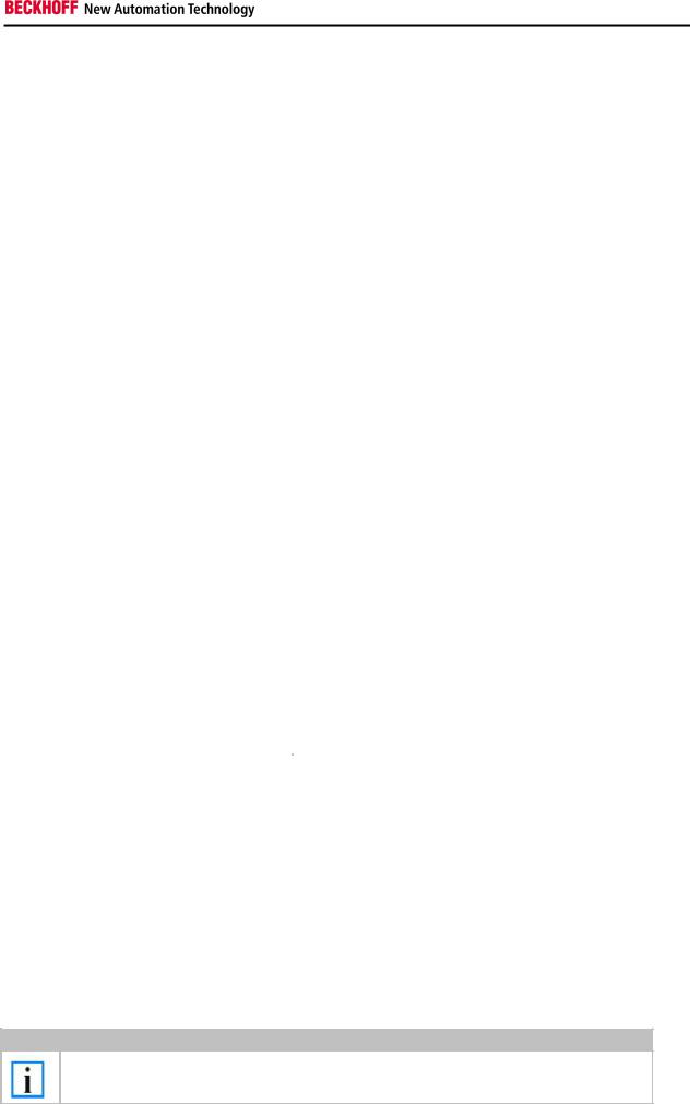
Display
Display setup
The display built-in the CX1100-000x units, is a LCD display. It features 2 lines with 16 characters. Each character has a resolution of 5 x 8 pixel. The font is named SPLC780C-11 and is fixed. The following figure shows the the font with all available characters.
For easy reading a background illumination is integrated to the display. The illumination can be switch on and off. This blinking can be used to attract the user in certain situations. The state can be set via the controller. The controller reads the registers in "Auxiliary Control Block" and addresses the display in the desired manner.
14 |
Embedded PC |
Product overview
Representing text on the display
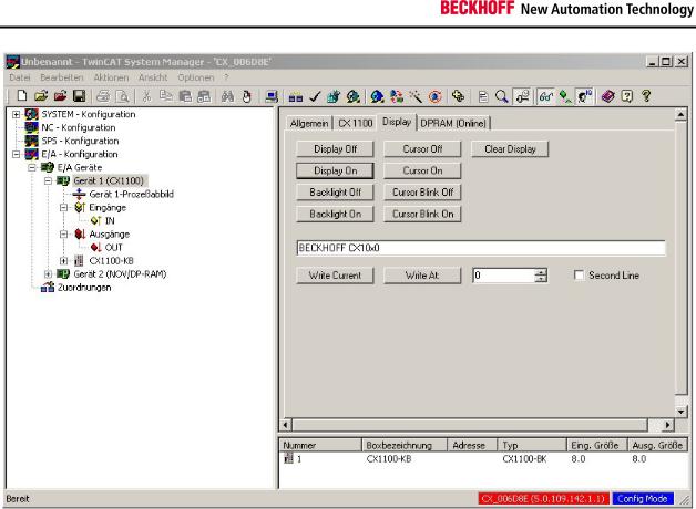
The display can be controlled in two ways with the aid of TwinCAT. One version is programming through the System Manager. A second possibility is for the display to be written by a function block directly from the PLC program.
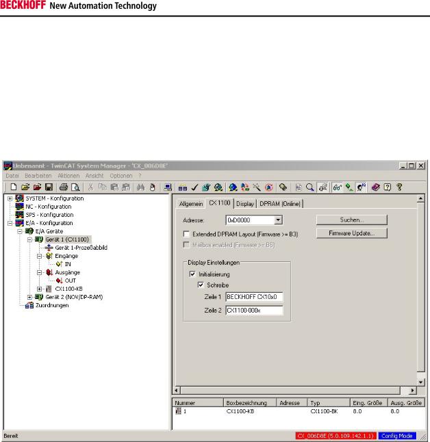
Settings in the System Manager
When the TwinCAT system starts, the text specified in the configuration can be written to the display. This text is set in the System Manager.
This is done by selecting the CX10x0 device in the hierarchy browser. Under the CX1100 tab it is possible to write both lines of the display in the "Display settings" area. This requires the fields at the location for initialisation and writing to be selected. The changes only take effect after the configuration has been written. When TwinCAT restarts, the set text is then displayed.
Embedded PC |
15 |
Product overview
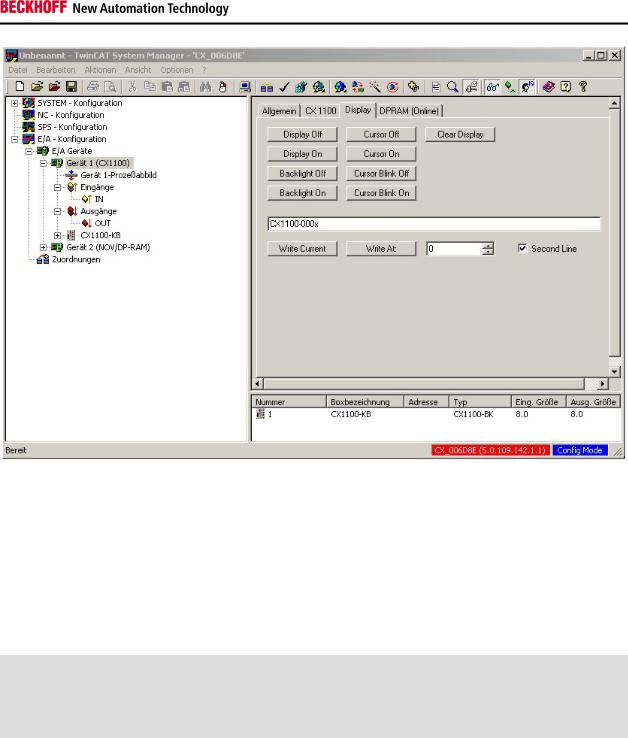
The display can be controlled directly through the Display tab. The corresponding functions are carried out immediately through the switches. It is possible to execute the following functions:
Switch the display on/off (text is displayed/hidden)
Background illumination on/off
Clear the display (text is cleared, and must be re-entered)
Cursor on/off (the cursor is displayed)
Cursor flash on/off (the cursor flashes)
The desired text is entered into the text input field. The "Write current" switch inserts the text at the current position of the cursor.
16 |
Embedded PC |
Product overview
Using the "Write At" switch, the numerical input box and the "Second Line" check box, it is possible to write to a specified position on the display. The useful range of values for the position extends from 0 to 15. The user should also, however, consider the length of the text. (Each line has 16 characters!) In the example illustrated below, the text "CX1100-000x" is written to Position 0 (the start of the line) on Line 2.
Settings in the PLC program
The function block FB_CX1000SetTextDisplay is provided in the library for the CX family (TcCX1000System.lib) in order to operate the display from a PLC program. All the functions of the display can be manipulated from this function block. The library must, however, be integrated through the library administrator. If this has been done, the block is available as a function block. It is instanced as such in the declarations part of the program.
PROGRAM MAIN
VAR
Display_0 : FB_CX1000SetTextDisplay;
END_VAR
It is then called from the program with its parameters. There are five parameters for this function block:
bExecute : BOOL
nDevID : UDINT
nMode : E_CX1000_DisplayModes
stLine |
: STRING(20) |
nCursorPos : DWORD
The command is executed in response to a rising edge at "bExecute". "nDevID" provides the Device ID of the CX1100 that is to be written to. The ID is displayed in the System Manager. (The General tab for the CX1100, top right). The parameter "stLine" is used to pass a text of at most 20 characters. Only the first 16 of these characters, however, will be displayed. The writing position of the text uses quoted through "nCursorPos". 0 to 15 is a useful range for this value. "nMode" selects the operating mode of the function block. The modes are:
|
e_CX1000_DisplayNoAction |
: No action. |
|
e_CX1000_DisplayOn |
: Switch on the display. |
Embedded PC |
|
17 |

Product overview
|
e_CX1000_DisplayOff |
: Switch off the display. |
|
e_CX1000_CursorOn |
: Switch on the cursor. |
|
e_CX1000_CursorOff |
: Switch off the cursor. |
|
e_CX1000_CursorBlinkOn |
: Switch on the cursor flashing. |
|
e_CX1000_CursorBlinkOff |
: Switch off the cursor flashing. |
e_CX1000_BackLightOn : Switch on the background illumination.
e_CX1000_BackLightOff : Switch off the background illumination.
|
e_CX1000_ClearDisplay |
: Clear the content of the screen. |
|
e_CX1000_WriteLine1 |
: Write to the first line. |
|
e_CX1000_WriteLine1 |
: Write to the second line. |
The call then looks like this:
Display_0( |
|
|
bExecute := write_now, |
(*write_now is a bool, function: switch) |
|
nDevID |
:= 1, |
(*DeviceID of the CX1100*) |
nMode |
:= e_CX1000_WRITELine1, |
(*Write to the first line of the display*) |
stLine |
:= 'Beckhoff CX1100', |
(*Fixed text or variable*) |
nCursorPos := 0 |
(*Writing position, e.g. 0 for start line*) |
|
); |
|
|
The block supplies a few status signals for evaluating the program environment. These can be used to provide feedback to the PLC program. There are three response signals from the function:
bBusy : BOOL
bErr : BOOL
nErrorID : UDINT
"bBusy" indicates that the command is at present being transferred by ADS. No new command will be accepted as long as "bBusy" remains TRUE. "bErr" reports an error in a call to a function block. (The signal becomes TRUE). "nErrorID" permits the error that has occurred to be analysed by means of an error number. The error number refers to an error in the ADS protocol.
18 |
Embedded PC |
 Loading...