


 Loading...
Documentation
EP9214-0023 and EP9224-0023
Power Distribution for EtherCAT Box
Version 2.0.0
Date 2015-05-13

|
|
|
|
|
Table of contents |
Table of contents |
|
|
|||
1 |
Foreword .................................................................................................................................................... |
|
|
4 |
|
|
1.1 |
Notes on the documentation............................................................................................................. |
|
4 |
|
|
1.2 |
Safety instructions ............................................................................................................................ |
|
5 |
|
|
1.3 |
Documentation issue status.............................................................................................................. |
|
6 |
|
2 |
Product overview....................................................................................................................................... |
|
7 |
||
|
2.1 |
EtherCAT Box - Introduction............................................................................................................. |
|
7 |
|
|
2.2 |
EP9214 - Introduction ....................................................................................................................... |
|
9 |
|
|
2.3 |
EP9224 - Introduction ..................................................................................................................... |
|
10 |
|
|
2.4 |
Technical data ................................................................................................................................ |
|
11 |
|
3 |
Mounting and cabling ............................................................................................................................. |
|
12 |
||
|
3.1 |
Mounting ......................................................................................................................................... |
|
12 |
|
|
|
3.1.1 |
Dimensions ......................................................................................................................... |
|
12 |
|
|
3.1.2 |
Mounting ............................................................................................................................. |
|
13 |
|
|
3.1.3 Nut torque for connectors ................................................................................................... |
|
13 |
|
|
3.2 |
EtherCAT ........................................................................................................................................ |
|
15 |
|
|
|
3.2.1 |
EtherCAT connection.......................................................................................................... |
|
15 |
|
|
3.2.2 |
EtherCAT - Fieldbus LEDs.................................................................................................. |
|
16 |
|
3.3 |
Power supply .................................................................................................................................. |
|
17 |
|
|
|
3.3.1 |
Power Connection............................................................................................................... |
|
17 |
|
|
3.3.2 |
Power LEDs ........................................................................................................................ |
|
19 |
|
|
3.3.3 |
Power cables ...................................................................................................................... |
|
20 |
|
|
3.3.4 Power cable conductor losses ............................................................................................ |
|
21 |
|
|
|
3.3.5 |
Power cable 7/8" ................................................................................................................. |
|
22 |
|
|
3.3.6 |
Conductor losses ................................................................................................................ |
|
23 |
|
|
3.3.7 |
Power outputs ..................................................................................................................... |
|
23 |
|
3.4 |
Status LEDs and status bits............................................................................................................ |
|
25 |
|
|
3.5 |
Monitoring and reset contacts......................................................................................................... |
|
26 |
|
4 |
Comissioning and Configuration........................................................................................................... |
|
28 |
||
|
4.1 |
Inserting into the EtherCAT network............................................................................................... |
|
28 |
|
|
4.2 |
Configuration via TwinCAT ............................................................................................................. |
|
31 |
|
|
4.3 |
Operation with or without EtherCAT master ................................................................................... |
38 |
||
|
4.4 |
Switch of behavior .......................................................................................................................... |
|
39 |
|
|
|
4.4.1 |
Switch-off characteristics .................................................................................................... |
|
39 |
|
|
4.4.2 Current limitation, switching the load circuits off ................................................................. |
41 |
||
|
|
4.4.3 Setting the current limitation ............................................................................................... |
|
42 |
|
|
|
4.4.4 Status LEDs and status bits................................................................................................ |
|
43 |
|
|
4.5 |
EP9214-0023.................................................................................................................................. |
|
45 |
|
|
|
4.5.1 |
EP9214-0023 - Object description ...................................................................................... |
45 |
|
|
|
4.5.2 |
EP9214-0023 - Process image ........................................................................................... |
61 |
|
|
4.6 |
EP9224-0023.................................................................................................................................. |
|
62 |
|
|
|
4.6.1 |
EP9224-0023 - Diagnostic functions................................................................................... |
62 |
|
|
|
4.6.2 |
EP9224-0023 - Object description ...................................................................................... |
75 |
|
|
|
4.6.3 |
EP9224-0023 - Process image ......................................................................................... |
102 |
|
|
4.7 |
Restoring the delivery state .......................................................................................................... |
|
104 |
|
5 |
Appendix ................................................................................................................................................ |
|
|
105 |
|
|
5.1 |
General operating conditions........................................................................................................ |
|
105 |
|
|
5.2 |
EtherCAT Box - Accessories ........................................................................................................ |
|
106 |
|
|
5.3 |
Support and Service ..................................................................................................................... |
|
107 |
|
|
|
|
|||
EP9214-0023 and EP9224-0023 |
Version 2.0.0 |
3 |
|||
Foreword
1 Foreword
1.1Notes on the documentation
This description is only intended for the use of trained specialists in control and automation engineering who are familiar with the applicable national standards.
It is essential that the following notes and explanations are followed when installing and commissioning these components.
The responsible staff must ensure that the application or use of the products described satisfy all the requirements for safety, including all the relevant laws, regulations, guidelines and standards.
Disclaimer
The documentation has been prepared with care. The products described are, however, constantly under development.
For that reason the documentation is not in every case checked for consistency with performance data, standards or other characteristics.
In the event that it contains technical or editorial errors, we retain the right to make alterations at any time and without warning.
No claims for the modification of products that have already been supplied may be made on the basis of the data, diagrams and descriptions in this documentation.
Trademarks
Beckhoff®, TwinCAT®, EtherCAT®, Safety over EtherCAT®, TwinSAFE®, XFC®and XTS® are registered trademarks of and licensed by Beckhoff Automation GmbH.
Other designations used in this publication may be trademarks whose use by third parties for their own purposes could violate the rights of the owners.
Patent Pending
The EtherCAT Technology is covered, including but not limited to the following patent applications and patents:
EP1590927, EP1789857, DE102004044764, DE102007017835
with corresponding applications or registrations in various other countries.
The TwinCAT Technology is covered, including but not limited to the following patent applications and patents:
EP0851348, US6167425 with corresponding applications or registrations in various other countries.
EtherCAT® is registered trademark and patented technology, licensed by Beckhoff Automation GmbH, Germany
Copyright
© Beckhoff Automation GmbH & Co. KG, Germany.
The reproduction, distribution and utilization of this document as well as the communication of its contents to others without express authorization are prohibited.
Offenders will be held liable for the payment of damages. All rights reserved in the event of the grant of a patent, utility model or design.
4 |
Version 2.0.0 |
EP9214-0023 and EP9224-0023 |
Foreword
1.2Safety instructions
Safety regulations
Please note the following safety instructions and explanations!
Product-specific safety instructions can be found on following pages or in the areas mounting, wiring, commissioning etc.
Exclusion of liability
All the components are supplied in particular hardware and software configurations appropriate for the application. Modifications to hardware or software configurations other than those described in the documentation are not permitted, and nullify the liability of Beckhoff Automation GmbH & Co. KG.
Personnel qualification
This description is only intended for trained specialists in control, automation and drive engineering who are familiar with the applicable national standards.
Description of symbols
In this documentation the following symbols are used with an accompanying safety instruction or note. The safety instructions must be read carefully and followed without fail!
Serious risk of injury!
Failure to follow the safety instructions associated with this symbol directly endangers the life and health of persons.
DANGER
Risk of injury!
Failure to follow the safety instructions associated with this symbol endangers the life and health of persons.
WARNING
Personal injuries!
Failure to follow the safety instructions associated with this symbol can lead to injuries to persons.
CAUTION
Damage to the environment or devices
Failure to follow the instructions associated with this symbol can lead to damage to the environment or equipment.
Attention
Tip or pointer
This symbol indicates information that contributes to better understanding.
Note
EP9214-0023 and EP9224-0023 |
Version 2.0.0 |
5 |

Foreword
1.3Documentation issue status
Version |
Comment |
|
2.0.0 |
• |
migration |
|
• chapter mounting and cabling updated |
|
|
• chapter nut torque for connectors extended |
|
|
• chapter switch off behavior updated |
|
|
• |
object descriptions updated |
1.1.0 |
• |
EP9224-0023 added |
1.0.0 |
• |
first release |
0.1 |
• preliminary version (only German available) |
|
Firm and hardware version
The documentation refers to the firm and hardware status that was valid at the time it was prepared.
The properties of the modules are subject to continuous development and improvement. Modules having earlier production statuses cannot have the same properties as modules with the latest status. Existing properties, however, are always retained and are not changed, so that these modules can always be replaced by new ones.
Documentation |
EP9214-0023 |
|
EP9224-0023 |
|
version |
firmware |
hardware |
firmware |
hardware |
2.0.0 |
09 |
10 |
04 |
10 |
1.1.0 |
09 |
06 |
04 |
06 |
1.0.0 |
07 |
03 |
- |
- |
0.1 |
07 |
03 |
- |
- |
The firmware and hardware version (delivery state) can be found in the batch number (D number) printed at the side of the EtherCAT Box.
Syntax of the batch number (D number)
WW YY FF HH
WW - week of production (calendar week)
YY - year of production
FF - firmware version
HH - hardware version
Example with ser. no.: 55 09 01 00:
55 - week of production 55
09 - year of production 2009
01 - firmware version 01
00 - hardware version 00
6 |
Version 2.0.0 |
EP9214-0023 and EP9224-0023 |
Product overview
2 Product overview
2.1EtherCAT Box - Introduction
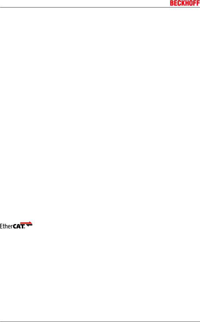
The EtherCAT system has been extended with EtherCAT Box modules with protection class IP 67. Through the integrated EtherCAT interface the modules can be connected directly to an EtherCAT network without an additional Coupler Box. The high-performance of EtherCAT is thus maintained into each module.
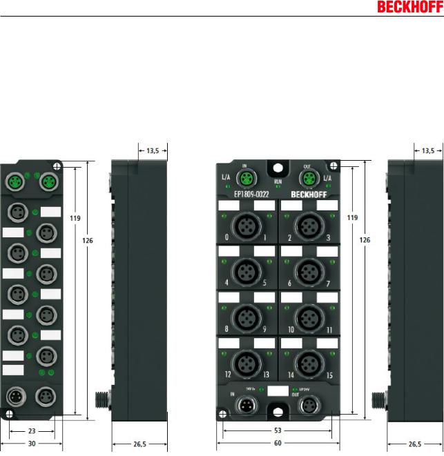
The extremely low dimensions of only 126 x 30 x 26.5 mm (h x w x d) are identical to those of the Fieldbus Box extension modules. They are thus particularly suitable for use where space is at a premium. The small mass of the EtherCAT modules facilitates applications with mobile I/O interface (e.g. on a robot arm). The EtherCAT connection is established via screened M8 connectors.
Fig. 1: EtherCAT Box Modules within an EtherCAT network
The robust design of the EtherCAT Box modules enables them to be used directly at the machine. Control cabinets and terminal boxes are now no longer required. The modules are fully sealed and therefore ideally prepared for wet, dirty or dusty conditions.
Pre-assembled cables significantly simplify EtherCAT and signal wiring. Very few wiring errors are made, so that commissioning is optimized. In addition to pre-assembled EtherCAT, power and sensor cables, fieldconfigurable connectors and cables are available for maximum flexibility. Depending on the application, the sensors and actuators are connected through M8 or M12 connectors.
The EtherCAT modules cover the typical range of requirements for I/O signals with protection class IP67:
•digital inputs with different filters (3.0 ms or 10 μs)
•digital outputs with 0.5 or 2 A output current
•analog inputs and outputs with 16 bit resolution
•Thermocouple and RTD inputs
•Stepper motor modules
XFC (eXtreme Fast Control Technology) modules, including inputs with time stamp, are also available.
EP9214-0023 and EP9224-0023 |
Version 2.0.0 |
7 |
Product overview
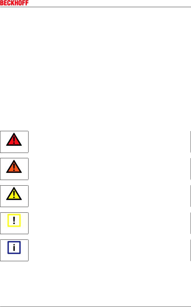
Fig. 2: EtherCAT Box with M8 connections for sensors/actuators
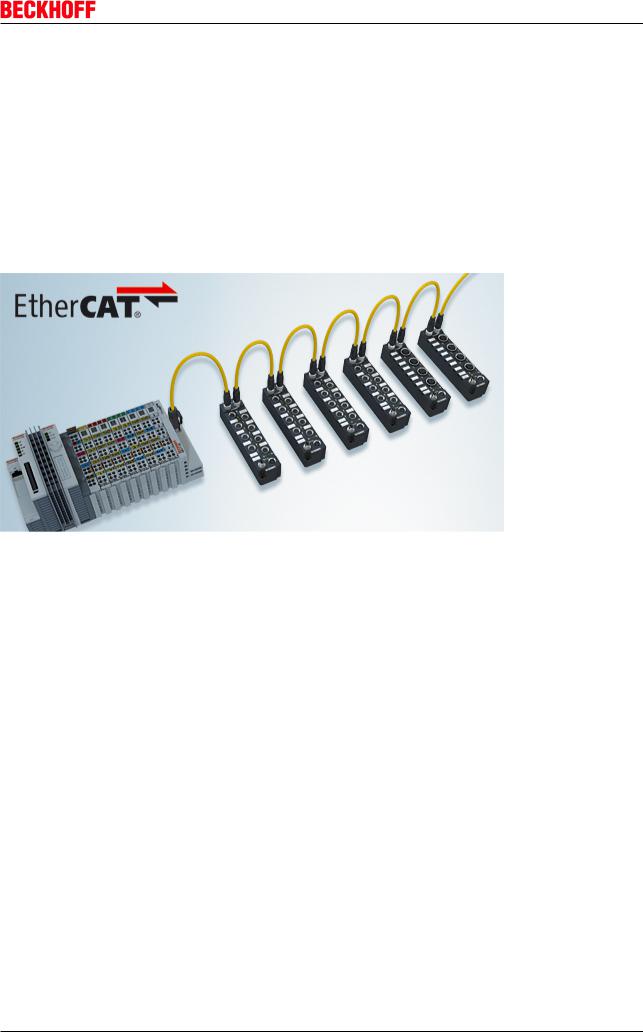
Fig. 3: EtherCAT Box with M12 connections for sensors/actuators
|
Basic EtherCAT documentation |
|
You will find a detailed description of the EtherCAT system in the Basic System Documen- |
Note |
tation for EtherCAT, which is available for download from our website (www.beckhoff.com) |
under Downloads. |
|
|
|
XML files
You will find XML files (XML Device Description Files) for Beckhoff EtherCAT modules on our website (www.beckhoff.com) under Downloads, in the Configuration Files area.
Note
8 |
Version 2.0.0 |
EP9214-0023 and EP9224-0023 |
Product overview
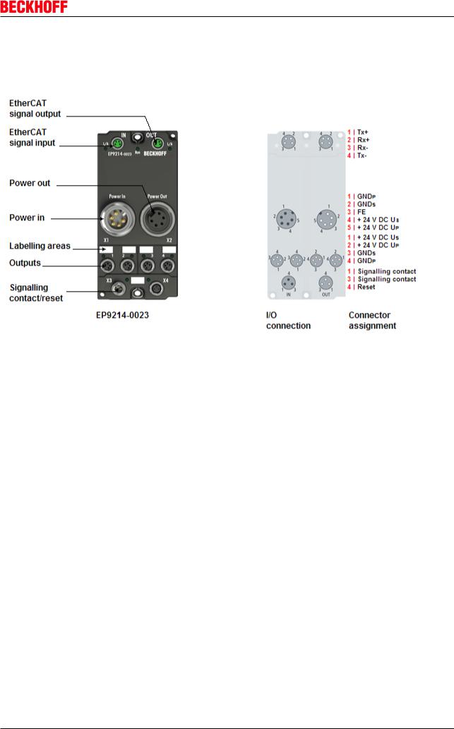
2.2EP9214 - Introduction
Fig. 4: EP9214
Power distribution for EtherCAT Box (24 VDC)
The EP9214-0023 enables connection of four power supply branches. In each branch the current consumption for the control voltage US and the peripheral voltage UP is monitored, limited, and, if necessary, switched off.
The power distribution is supplied via a 7/8" connector with up to 16 A (per voltage supply US/UP). Several modules can be configured in a cascade arrangement. In the event of a short-circuit in one of the four outputs, the affected output is switched off. The supply for the other branches remains active. The switch-off and control is done in such a way that the input voltage does not fall below 21 V or other modules are going down, caused by undervoltage.
During startup consumers with large capacities can be added without problem.
The master can read diagnostic messages from the individual channels via the EtherCAT interface. Independent switching of individual consumer branches is also possible via the EtherCAT master.
In delivery state the eight outputs of the box (4 times Us, 4 times Up) are activated to enable operation without EtherCAT.
After an error caused the switch off of a channel, this channel remains switched of when you try to switch it on again and has to be set back actively by the EtherCAT master or a hardware reset at the box (lower M8 socket).
Quick links
Installation
Configuration
UL requirements for UL approved modules
EP9214-0023 and EP9224-0023 |
Version 2.0.0 |
9 |
Product overview
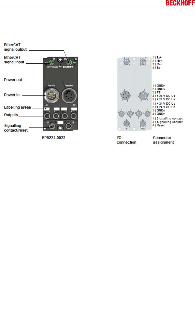
2.3EP9224 - Introduction
Fig. 5: EP9224
Power distribution for EtherCAT Box (24 VDC) with data logging
The EP9224-0023 enables connection of four power supply branches. In each branch the current consumption for the control voltage US and the peripheral voltage UP is monitored, limited, and, if necessary, switched off.
The power distribution is supplied via a 7/8" connector with up to 16 A (per voltage supply US/UP). Several modules can be configured in a cascade arrangement. In the event of a short-circuit in one of the four outputs, the affected output is switched off. The supply for the other branches remains active. The switch-off and control is done in such a way that the input voltage does not fall below 21 V or other modules are going down, caused by undervoltage.
During startup consumers with large capacities can be added without problem.
The master can read diagnostic messages from the individual channels via the EtherCAT interface. Independent switching of individual consumer branches is also possible via the EtherCAT master.
In delivery state the eight outputs of the box (4 times Us, 4 times Up) are activated to enable operation without EtherCAT.
After an error caused the switch off of a channel, this channel remains switched of when you try to switch it on again and has to be set back actively by the EtherCAT master or a hardware reset at the box (lower M8 socket).
Additional to this basic functionality that is also provided by EP9214, the EP9224 displays the voltage values of PowerIn supply and all current values of inputs and outputs within the process data.
The box has got an internal log file, that is writing the system values continuously into a ring buffer. This data logging has to be activated at the startup.
In error case it is stopped, so a history of the system parameters from before the error case can be read out. This enables a much quicker error localization.
10 |
Version 2.0.0 |
EP9214-0023 and EP9224-0023 |
Product overview
Quick links
Installation
Configuration
UL requirements for UL approved modules
2.4Technical data
Technical data |
EP9214-0023 |
EP9224-0023 |
Rated voltage |
24 VDC (-15 % / +20 %) |
|
Power supply |
Feed: Plug 7/8", max. 16 A for each Us/Up |
|
|
Onward connection: Socket 7/8", max. 16 A for each Us/Up |
|
Number of load outputs |
4 x M8, for each Us and Up |
|
Voltage drop VON in the load |
90 mV / Ampere |
|
circuits |
|
|
Parallel connection of several load |
not permissible |
|
outputs |
|
|
Overload switch-off |
dependent on selected load curve (20 ms at 3 x IN, see time/current |
|
|
characteristics) |
|
Temperature switch-off |
Internal temperature switch-off |
|
Switch-on delay |
10, 100 or 200 ms (adjustable via CoE) |
|
Selectivity |
in case of an error, the channel concerned is switched off |
|
Signalling contact |
1 |
|
Reset contact |
1 |
|
Connections for signal and reset |
in : 1 x M8 plug |
|
contacts |
out : 1 x M8 socket |
|
Fieldbus |
EtherCAT |
|
Fieldbus connection |
2 x M8 sockets, screened, marked green |
|
Electrical isolation |
Control voltage/fieldbus: 500 V |
|
Supply of the module circuitry |
from the control voltage Us |
|
Current consumption of the module |
typically 110 mA from Us, |
|
circuitry |
typically 40 mA from Up |
|
Process image |
Inputs: 5 x 16 bit |
Inputs: 16 x 16 Bit |
|
Outputs: 5 x 16 bit |
Outputs: 5 x 16 Bit |
Data logging |
- |
40 samples ( 1 ms - 1000 ms |
|
|
sample time) |
Permissible ambient temperature |
-25°C ... +60°C |
|
during operation |
|
|
Permissible ambient temperature |
-25 °C... +85°C |
|
during storage |
|
|
Vibration / shock resistance |
conforms to EN 60068-2-6 / EN 60068-2-27 |
|
EMC immunity/emission |
conforms to EN 61000-6-2 / EN 61000-6-4 |
|
Dimensions |
126 mm x 60 mm x 40 mm |
|
Weight |
approx. 450 g |
|
Installation position |
variable |
|
Protection class |
IP65, IP66, IP67 (according to EN 60529) |
|
Approvals |
CE, UL in preparation |
|
EP9214-0023 and EP9224-0023 |
Version 2.0.0 |
11 |
Mounting and cabling
3 Mounting and cabling
3.1Mounting
3.1.1Dimensions
Fig. 6: Dimensions of the EtherCAT Box Modules
All dimensions are given in millimeters.
Housing properties
EtherCAT Box |
lean body |
wide body |
Housing material |
PA6 (polyamide) |
|
Casting compound |
Polyurethane |
|
Mounting |
two fastening holes Ø 3 mm for M3 |
two fastening holes Ø 3 mm for M3 |
|
|
two fastening holes Ø 4,5 mm for M4 |
Metal parts |
Brass, nickel-plated |
|
Contacts |
CuZn, gold-plated |
|
Power feed through |
max. 4 A |
|
Installation position |
variable |
|
Protection class |
IP65, IP66, IP67 (conforms to EN 60529) when screwed together |
|
Dimensions (H x W x D) |
ca. 126 x 30 x 26,5 mm |
ca. 126 x 60 x 26,5 mm |
Weight |
approx. 125 g, depending on module type |
approx. 250 g, depending on module |
|
|
type |
|
|
|
12 |
Version 2.0.0 |
EP9214-0023 and EP9224-0023 |
Mounting and cabling
3.1.2Mounting
EP9214 modules are mounted using two M3 bolts in the mounting holes located in the corners or using two M4 bolts in the centrally located mounting holes.
The bolts must be longer than 15 mm. The mounting holes in the modules have no thread.
Protect connectors against soiling
Protect all module connections from soiling during installation!The protection classes IP65, IP66, IP67 (in accordance with EN 60529) are ensured only if all connectors are wired or
Note sealed! Unused connectors must be sealed with suitable protective caps (see Beckhoff catalogue for connector sets and protective caps)!
Cooling plate
The EP9214 module has a cooling plate on the underside. For the effective dissipation of the resultant power loss, the box must be bolted to a metal base, e.g. the machine bed, if
Note possible making contact over the entire surface.A temperature-related automatic switch-off of the box can occur if care is not taken to ensure that the power loss from the module is dissipated via the cooling plate. A corresponding temperature error bit is then set!
Note when mounting that the overall height is increased further by the fieldbus connections. See the Accessories section
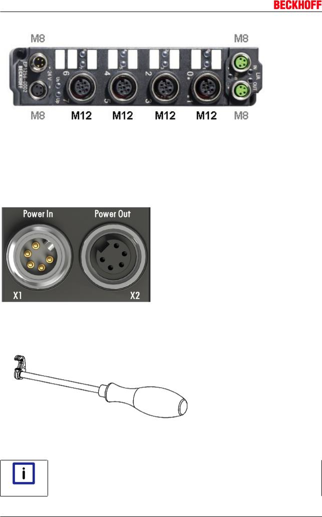
3.1.3Nut torque for connectors
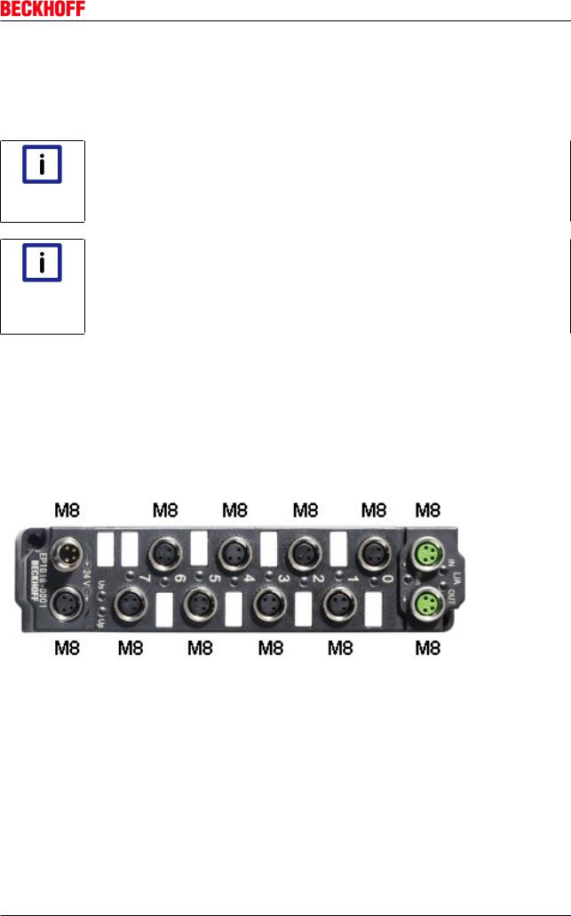
M8 connectors
It is recommended to pull the M8 connectors tight with a nut torque of 0.4 Nm.
Fig. 7: EtherCAT Box with M8 connectors
M12 connectors
It is recommended to pull the M12 connectors tight with a nut torque of 0.6 Nm.
EP9214-0023 and EP9224-0023 |
Version 2.0.0 |
13 |
Mounting and cabling
Fig. 8: EtherCAT Box with M8 and M12 connectors
7/8" connectors
It is recommended to pull the 7/8" connectors tight with a nut torque of 1.5 Nm.
Fig. 9: 7/8" connectors
Torque socket wrenches
Fig. 10: ZB8800 torque socket wrench
Ensure the right torque
Use the torque socket wrenches available by Beckhoff to pull the connectors tight (see accessories)!
Note
14 |
Version 2.0.0 |
EP9214-0023 and EP9224-0023 |
Mounting and cabling
Also see about this
2 EtherCAT Box - Accessories [} 106]
3.2EtherCAT
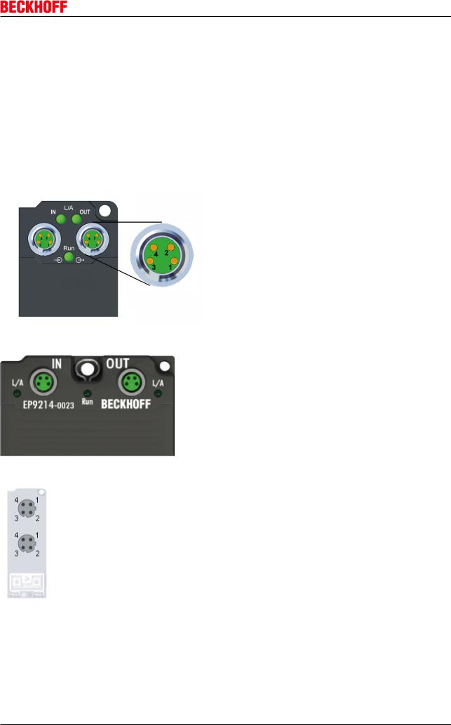
3.2.1EtherCAT connection
For the incoming and ongoing EtherCAT connection,
•the EtherCAT Box (EPxxxx) has two M8 sockets, marked in green
•the Coupler Box (FBB-x110) has two M12 sockets
Fig. 11: EtherCAT Box: M8 (30 mm housing)
Fig. 12: EtherCAT Box: M8 60 mm housing (EP9214 for example )
Fig. 13: Coupler Box: M12
Assignment
There are various different standards for the assignment and colors of connectors and cables for Ethernet/ EtherCAT.
EP9214-0023 and EP9224-0023 |
Version 2.0.0 |
15 |
Mounting and cabling
Ethernet/EtherCAT |
Plug connector |
Cable |
|
Standard |
|||
Signal |
Descrip- |
M8 |
M12 |
RJ451 |
ZB9010, ZB9020, |
ZB9031 and old |
TIA-568B |
|
tion |
|
|
|
ZB9030, ZB9032, |
versions |
|
|
|
|
|
|
ZK1090-6292, |
of ZB9030, ZB9032, |
|
|
|
|
|
|
ZK1090-3xxx-xxxx |
ZK1090-3xxx-xxxx |
|
Tx + |
Transmit |
Pin 1 |
Pin 1 |
Pin 1 |
yellow2 |
orange/white3 |
white/ |
|
Data+ |
|
|
|
|
|
orange |
Tx - |
Transmit |
Pin 4 |
Pin 3 |
Pin 2 |
orange2 |
orange3 |
orange |
|
Data- |
|
|
|
|
|
|
Rx + |
Receive |
Pin 2 |
Pin 2 |
Pin 3 |
white2 |
blue/white3 |
white/green |
|
Data+ |
|
|
|
|
|
|
Rx - |
Receive |
Pin 3 |
Pin 4 |
Pin 6 |
blue2 |
blue3 |
green |
|
Data- |
|
|
|
|
|
|
Shield |
Shield |
Housing |
Shroud |
Screen |
Screen |
Screen |
|
1) colored markings according to EN 61918 in the four-pin RJ45 connector ZS1090-0003
2) wire colors according to EN 61918
3) wire colors
Assimilation of color coding for cable ZB9030, ZB9032 and ZK1090-3xxxx- xxxx (with M8 connectors)
For unification the prevalent cables ZB9030, ZB9032 and ZK1090-3xxx-xxxx this means Note the pre assembled cables with M8 connectors were changed to the colors of EN61918 (yel-
low, orange, white, blue).So different color coding exists. But the electrical properties are absolutely identical.
EtherCAT connectors
The following connectors can be supplied for use in Beckhoff EtherCAT systems.
Designation |
Plug connector |
Comment |
ZS1090-0003 |
RJ45 |
four-pin, IP20, for field assembly |
ZS1090-0004 |
M12 |
four-pin, IP67, for field assembly |
ZS1090-0005 |
RJ45 |
eight-pin, IP20, for field assembly, |
|
|
suitable for Gigabit Ethernet |
ZS1090-0006 |
M8 |
four-pin, IP67, for field assembly |
ZS1090-0007 |
M8 socket |
four-pin, IP67, for field assembly, for ZB903x cable |
ZS1090-1006 |
M8 plug |
four-pin, IP67, for field assembly up to OD = 6.5 mm |
ZS1090-1007 |
M8 socket |
four-pin, IP67, for field assembly up to OD = 6.5 mm |
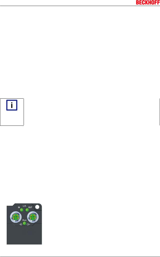
3.2.2EtherCAT - Fieldbus LEDs
Fig. 14: EtherCAT-LEDs
16 |
Version 2.0.0 |
EP9214-0023 and EP9224-0023 |
|
|
|
Mounting and cabling |
LED display |
|
|
|
|
|
|
|
LED |
|
Display |
Meaning |
IN L/A |
|
off |
no connection to the preceding EtherCAT module |
|
|
Lit |
LINK: connection to the preceding EtherCAT module |
|
|
flashing |
ACT: Communication with the preceding EtherCAT module |
OUT L/A |
|
off |
no connection to the following EtherCAT module |
|
|
Lit |
LINK: connection to the following EtherCAT module |
|
|
flashing |
ACT: Communication with the following EtherCAT module |
Run |
|
off |
Status of the EtherCAT module is Init |
|
|
flashes quickly |
Status of the EtherCAT module is pre-operational |
|
|
flashes slowly |
Status of the EtherCAT module is safe-operational |
|
|
Lit |
Status of the EtherCAT module is operational |
|
|
||
|
EtherCAT statuses |
||
|
The various statuses in which an EtherCAT module may be found are described in the Ba- |
||
Note |
sic System Documentation for EtherCAT, which is available for download from our website |
||
(www.beckhoff.com) under Downloads. |
|||
|
|
|
|
3.3Power supply
3.3.1Power Connection
Use cables with suitable cross-sections!
Ensure that the cross-sections of the cables employed are suitable for the load circuit inputs and outputs and the respective rated current being used!
Attention
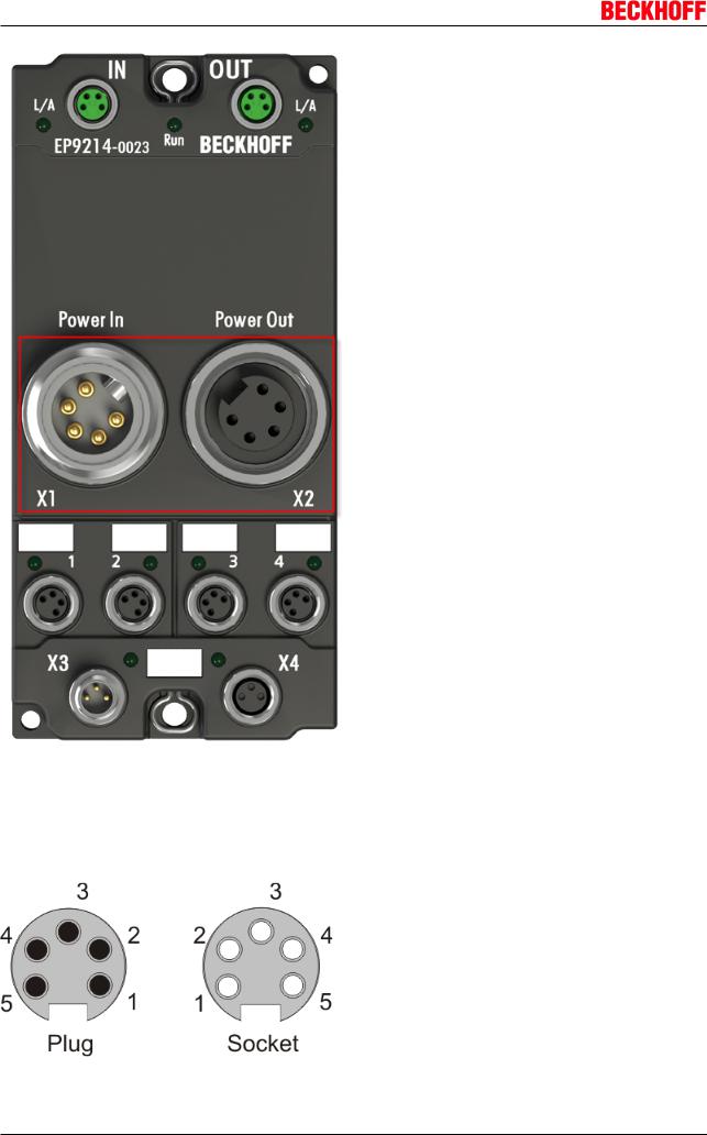
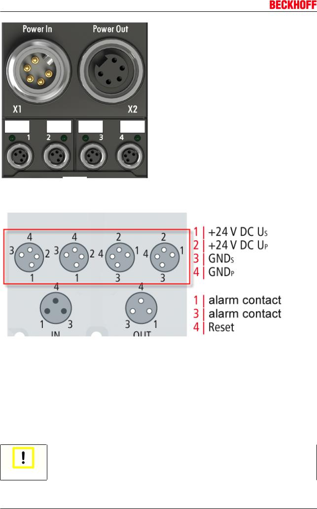
The supply voltages are fed and relayed onward via two 7/8" connectors in the center of the modules:
•Power In: left-hand 7/8" plug for the feed-in of supply voltages
•Power Out: right-hand 7/8" socket for the onward feeding of supply voltages
EP9214-0023 and EP9224-0023 |
Version 2.0.0 |
17 |
Mounting and cabling
Fig. 15: EP9214-0023 - 7/8" connectors
The contacts of the 7/8" plug connectors can conduct a maximum current of 16 A (40°C). Two LEDs next to the device identifier label indicate the status of the supply voltages.
Pin assignment
Fig. 16: Pin assignment of 7/8" plug connectors
18 |
Version 2.0.0 |
EP9214-0023 and EP9224-0023 |
|
|
Mounting and cabling |
|
|
|
Contact |
|
Voltage |
1 |
|
GND Up |
2 |
|
GND Us |
3 |
|
FE (Functional earth), (as well as contact at central mounting holes) |
4 |
|
Control voltage Us, +24 VDC |
5 |
|
Peripheral voltage Up, +24 VDC |
|
|
|
|
Do not confuse the power output with the EtherCAT connection! |
|
|
Never connect the power cables (M8, 24 VDC) to the green-marked EtherCAT sockets of |
|
Attention |
the EtherCAT Box Modules. This can cause the destruction of the modules! |
|
|
|
|
Control voltage Us: 24VDC
The fieldbus and the processor logic are supplied from the 24 VDC control voltage Us. The control voltage is electrically isolated from the fieldbus circuitry.
Peripheral voltage Up: 24VDC
The peripheral voltage Up is monitored and fed to the power outputs, but is not used in the EP9214.
Redirection of the supply voltages
The power connections Power In and Power Out are bridged in the module. Hence, the supply voltages Us and Up can be passed from EtherCAT Box to EtherCAT Box in a simple manner.
Observe the maximum current of the 7/8" plug connectors!
Also ensure when relaying the supply voltages Us and Up onward that the maximum permissible current of 16 A / 40 °C for each 7/8" plug connector is not exceeded!
Attention
3.3.2Power LEDs
Status-LEDs for the power supply
EP9214-0023 and EP9224-0023 |
Version 2.0.0 |
19 |

Mounting and cabling
LED |
Display |
Meaning |
Us (control voltage) |
off |
The power supply voltage, Us, is |
|
|
not present |
|
Green illuminated |
The power supply voltage, Us, is |
|
|
present |
Up (peripheral voltage) |
off |
The power supply voltage, Up, is |
|
|
not present |
|
Green illuminated |
The power supply voltage, Up, is |
|
|
present |
3.3.3Power cables
Ordering data
Order designation |
Power lead |
Screw-in |
Contacts |
Cross-section |
Length |
|
|
connector |
|
|
|
ZK2020-3200-0020 |
Straight socket, open end |
M8 |
4-pin |
0.34 mm2 |
2.00 m |
ZK2020-3200-0050 |
|
|
|
|
5.00 m |
ZK2020-3200-0100 |
|
|
|
|
10.00 m |
ZK2020-3400-0020 |
Angled socket, open end |
|
|
|
2.00 m |
ZK2020-3400-0050 |
|
|
|
|
5.00 m |
ZK2020-3400-0100 |
|
|
|
|
10.00 m |
ZK2020-3132-0001 |
Straight socket, straight |
|
|
|
0.15 m |
|
socket |
|
|
|
|
ZK2020-3132-0005 |
|
|
|
0.50 m |
|
ZK2020-3132-0010 |
|
|
|
|
1.00 m |
ZK2020-3132-0020 |
|
|
|
|
2.00 m |
ZK2020-3132-0050 |
|
|
|
|
5.00 m |
ZK2020-3334-0001 |
Angled socket, angled |
|
|
|
0.15 m |
|
socket |
|
|
|
|
ZK2020-3334-0005 |
|
|
|
0.50 m |
|
ZK2020-3334-0010 |
|
|
|
|
1.00 m |
ZK2020-3334-0020 |
|
|
|
|
2.00 m |
ZK2020-3334-0050 |
|
|
|
|
5.00 m |
Further available power cables may be found in the Beckhoff catalog or on our internet pages (http://
www.beckhoff.com).
Technical data
Technical data
Rated voltage according to IEC60 664-1 |
60 VAC / 75 VDC |
Contamination level according to IEC 60 664-1 |
3/2 |
Insulation resistance IEC 60 512-2 |
>109W |
Current carrying capacity according to IEC 60512-3 |
4 A |
Volume resistance according to IEC 60512-2 |
< 5 mW |
Protection class according to IEC 60529 |
IP65/66/67, when screwed together |
Ambient temperature |
-30°C to +80°C |
20 |
Version 2.0.0 |
EP9214-0023 and EP9224-0023 |
Mounting and cabling
3.3.4Power cable conductor losses
The ZK2020-xxxx-yyyy power cables should not exceed the total length of 15 m at 4 A (with continuation). When planning the cabling, note that at 24 V nominal voltage, the functionality of the module can no longer be assured if the voltage drop reaches 6 V. Variations in the output voltage from the power supply unit must also be taken into account.
Fig. 17: Power cable conductor losses
Example
8 m power cable with 0.34 mm² cross-section has a voltage drop of 3.2 V at 4 A.
EP92x4 Power Distribution Modules
With EP9214 and EP9224 Power Distribution Modules intelligent concepts for voltage supply are available. Further information may be found under www.beckhoff.com/EP9224.
Note
EP9214-0023 and EP9224-0023 |
Version 2.0.0 |
21 |
Mounting and cabling
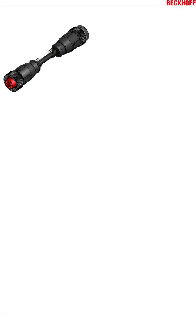
3.3.5Power cable 7/8"
Fig. 18: Power cable 7/8"
Ordering data
Order identifier |
Power cable |
Screw type |
Contacts |
Cross-sec- |
Length |
|
|
connector |
|
tion |
|
ZK2030-1200-0010 |
Straight socket, open end |
7/8" |
5-pin |
1,50 mm2 |
1.00 m |
ZK2030-1200-0030 |
|
|
|
|
3.00 m |
ZK2030-1200-0050 |
|
|
|
|
5.00 m |
ZK2030-1200-0100 |
|
|
|
|
10.00 m |
ZK2030-1400-0010 |
Angled socket, open end |
|
|
|
1.00 m |
ZK2030-1400-0030 |
|
|
|
|
3.00 m |
ZK2030-1400-0050 |
|
|
|
|
5.00 m |
ZK2030-1400-0100 |
|
|
|
|
10.00 m |
ZK2030-1112-0010 |
Straight socket, straight |
|
|
|
1.00 m |
ZK2030-1112-0030 |
plug |
|
|
|
3.00 m |
ZK2030-1112-0050 |
|
|
|
|
5.00 m |
ZK2030-1112-0100 |
|
|
|
|
10.00 m |
ZK2030-1314-0010 |
Angled socket, angled |
|
|
|
1.00 m |
|
plug |
|
|
|
|
ZK2030-1314-0030 |
|
|
|
3.00 m |
|
ZK2030-1314-0050 |
|
|
|
|
5.00 m |
ZK2030-1314-0100 |
|
|
|
|
10.00 m |
Further available power cables and the associated data sheets can be found in the Beckhoff catalogue or on our website (http://www.beckhoff.com).
22 |
Version 2.0.0 |
EP9214-0023 and EP9224-0023 |
|
Mounting and cabling |
Technical data |
|
|
|
Technical data |
|
Rated voltage according to IEC 61076-2-101 |
300 V (according to IEC 61076-2-101) |
Contamination level according to IEC 60664-1 |
3/2 (according to IEC 60664-1) |
Insulation resistance IEC 60512-2 |
>109W |
Current carrying capacity according to |
16 A at 40°C (according to IEC 60512-3) |
IEC 60512-3 |
|
Volume resistance according to IEC 60512-2 |
< 5 mW |
Protection class conforms to IEC 60529 |
IP65/66/67, when screwed together |
Permissible ambient temperature |
-30°C to +80°C |
Material properties |
TPE-U (PUR) halogen-free according to DIN VDE 0472 |
|
Part 815, |
|
flame-retardant according to cULus 20549 |
Approbations |
UL |
Cable outside diameter |
7.80 ± 0.20 mm |
Bending radius |
min. 6 x D (external diameter) |
Parameter |
Max. speed 5 m/s, max. acceleration 10 m/s² |
Number of cycles |
At least 10 million cycles with a max. travel path of 20 |
|
meters |
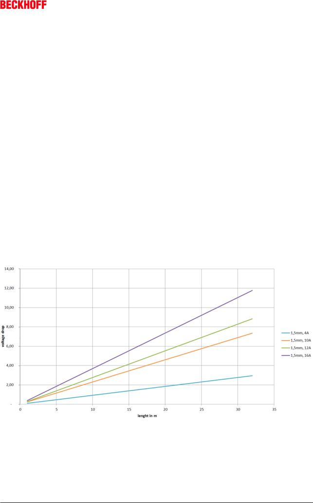
3.3.6Conductor losses
In the case of the power cables ZK2030-xxxx-yyy, a total length of 15 m should not be exceeded at 16 A. When wiring, note that with a rated voltage of 24 V the function of the modules can no longer be guaranteed from a voltage drop of 6 V. Variations in the output voltage from the power supply unit must also be taken into account.
Fig. 19: ZK2030-xxxx-yyy - Conductor losses
Alternatively, larger cable cross-section can be used, e.g. 2.5 mm2.
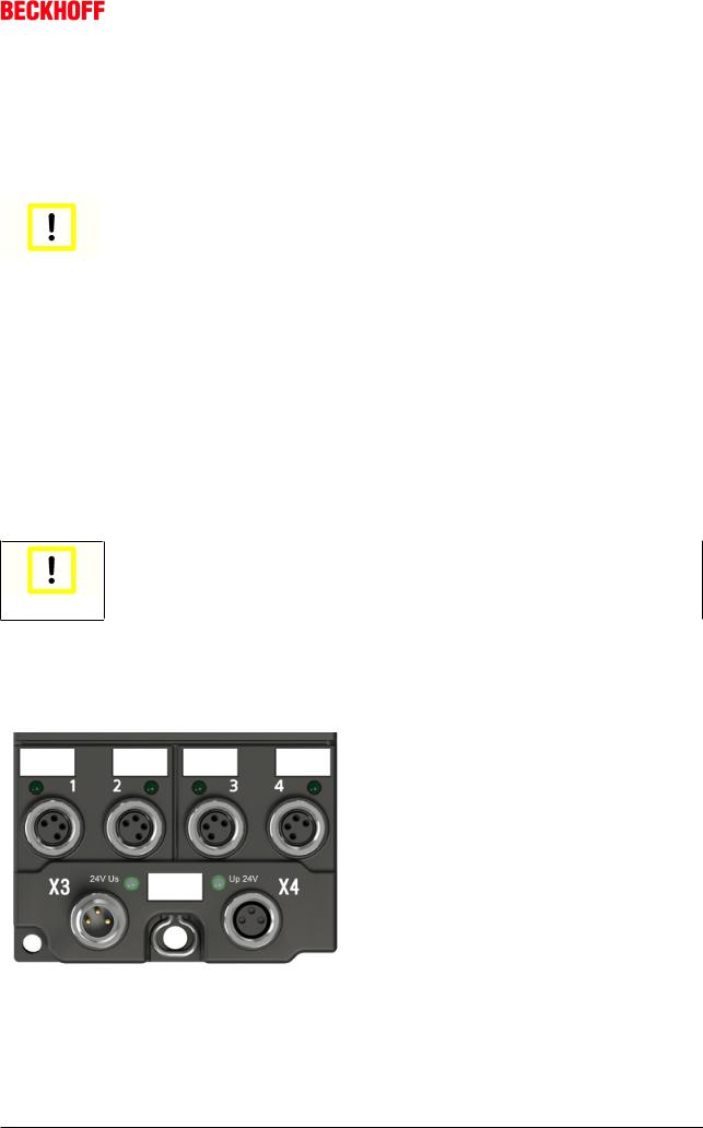
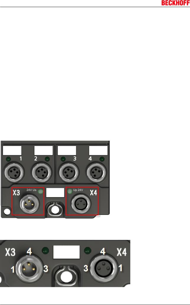
3.3.7Power outputs
The supply voltages are output via four 4-pole M8 sockets in the lower third of the modules (1, 2, 3 and 4).
EP9214-0023 and EP9224-0023 |
Version 2.0.0 |
23 |
Mounting and cabling
Fig. 20: M8 sockets
Pin assignment
Fig. 21: Pin assignment of the M8 sockets
Contact |
Voltage |
|
1 |
Control voltage Us, +24 VDC |
|
2 |
Peripheral voltage Up, +24 VDC |
|
3 |
GNDs* |
*) can be internally connected to one another depending on the connected |
4 |
GNDp* |
module: see individual module descriptions |
The contacts of the M8 plug connectors can conduct a maximum current of 4 A.
A LED indicates the status of the power outputs.
Do not confuse the power outputs with the EtherCAT connection
Never connect the power cables (M8, 24 VDC) to the green-marked EtherCAT sockets of the EtherCAT Box Modules. This can cause the destruction of the modules!
Attention
24 |
Version 2.0.0 |
EP9214-0023 and EP9224-0023 |
Mounting and cabling
Control voltage Us: 24 VDC
Power is supplied to the fieldbus, the processor logic, the inputs and the sensors from the control voltage Us (24 VDC). The control voltage is electrically isolated from the fieldbus circuitry.
Peripheral voltage Up: 24 VDC
The peripheral voltage Up (24 VDC) supplies the digital outputs; it can be brought in separately. Hence, if the load voltage is switched off, the fieldbus function as well as the supply and function of the inputs are retained.
Electrical isolation
The grounds of the control voltage (GNDs) and peripheral voltage (GNDp) are electrically isolated from each other in order to ensure the electrical isolation of the peripheral devices on Up from the control voltage.
The electrical isolation can be nullified
If you connect digital and analog EtherCAT Box Modules directly to one another via fourpole power lines, then there may no longer be any electrical isolation due to the connected
Attention boxes!
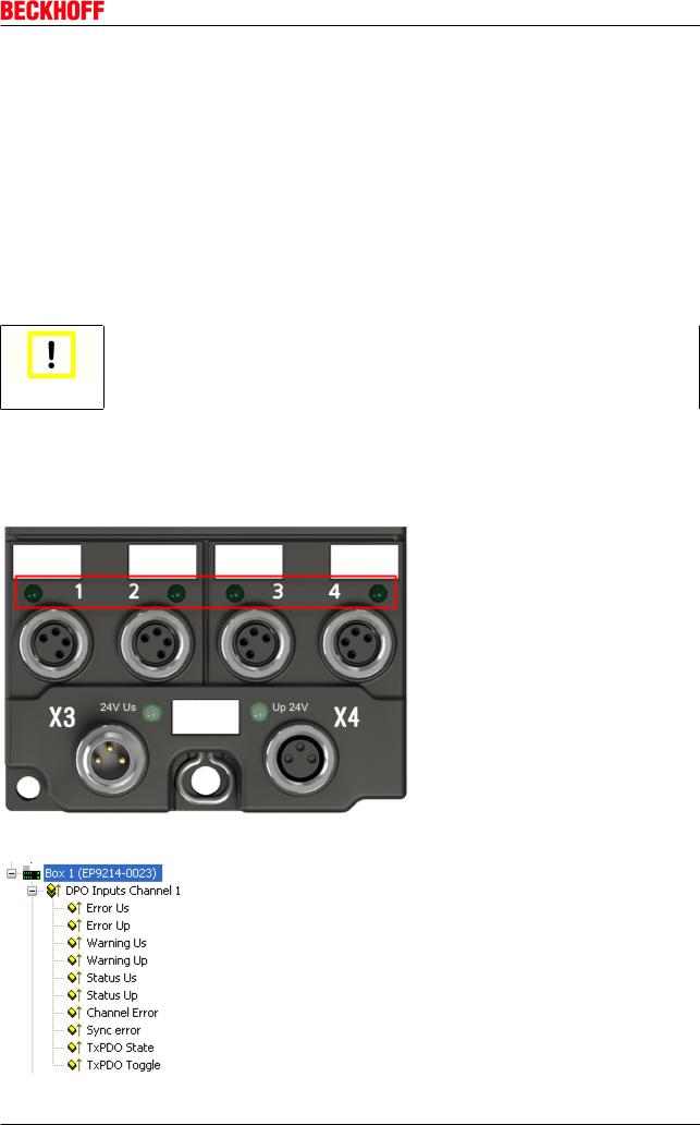
3.4Status LEDs and status bits
Below is a table showing the meaning of the status LEDs and status bits for the power outputs (EP9214 for example):
Fig. 22: EP9214 - status LEDs
Fig. 23: EP9214 - status bits
EP9214-0023 and EP9224-0023 |
Version 2.0.0 |
25 |
Mounting and cabling
Initialization
When switching on the voltage supply to the EP9214 / EP9224, all green LEDs and then all red LEDs are switched on briefly to test the LEDs.
The LED is valid for both voltages and currents (Us and Up; OR).
LED |
Status |
Warning |
Error |
Description |
|
Us / Up |
|
Us / Up |
|
Off |
0 |
0 |
0 |
The output is ready |
Green |
1 |
0 |
0 |
The output is just switching on |
Green |
1 |
0 |
0 |
The output is switched on. Normal operating status. |
Flashing |
1 |
1 |
0 |
The output is still operating, but will switch off if conditions |
green |
|
|
|
remain unchanged (Warning Ux). |
Flashing |
0 |
1 |
1 |
The output has been switched off. Switching on again is not |
red |
|
|
|
yet possible (waiting time of 20 seconds) |
Red |
0 |
0 |
1 |
The output has been deactivated and can be returned to a |
|
|
|
|
normal state by a reset. |
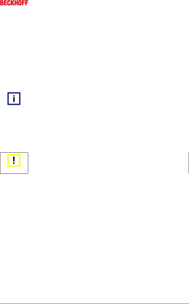
3.5Monitoring and reset contacts
The EP9214 has a monitoring contact (signal contact) and a reset contact. These contacts are fed out via an M8 plug and an M8 socket.
The contacts of this M8 plug and M8 socket are wired together 1:1.
Fig. 24: EP9214 - Monitoring and reset connectors
Pin assignment
Fig. 25: EP9214 - Monitoring and reset contacts
26 |
Version 2.0.0 |
EP9214-0023 and EP9224-0023 |

|
Mounting and cabling |
|
|
Contact |
Meaning |
Pin 1 and 3: |
Potential-free signalling contact (normally open contact), closes on application of the |
Monitoring |
supply voltage and if an error occurs in one of the eight load circuits |
Pin 4: Reset |
all errors are reset by applying 24 VDC to the Reset contact. |
The contacts of the M8 plug connectors can conduct a maximum current of 4 A.
EP9214-0023 and EP9224-0023 |
Version 2.0.0 |
27 |
Comissioning and Configuration
4 Comissioning and Configuration
4.1Inserting into the EtherCAT network
|
Installation of the latest XML device description |
|
Please ensure that you have installed the latest XML device description in TwinCAT. This |
Note |
can be downloaded from the Beckhoff website (http://www.beckhoff.de/english/default.htm? |
download/elconfg.htm) and installed according to the installation instructions. |
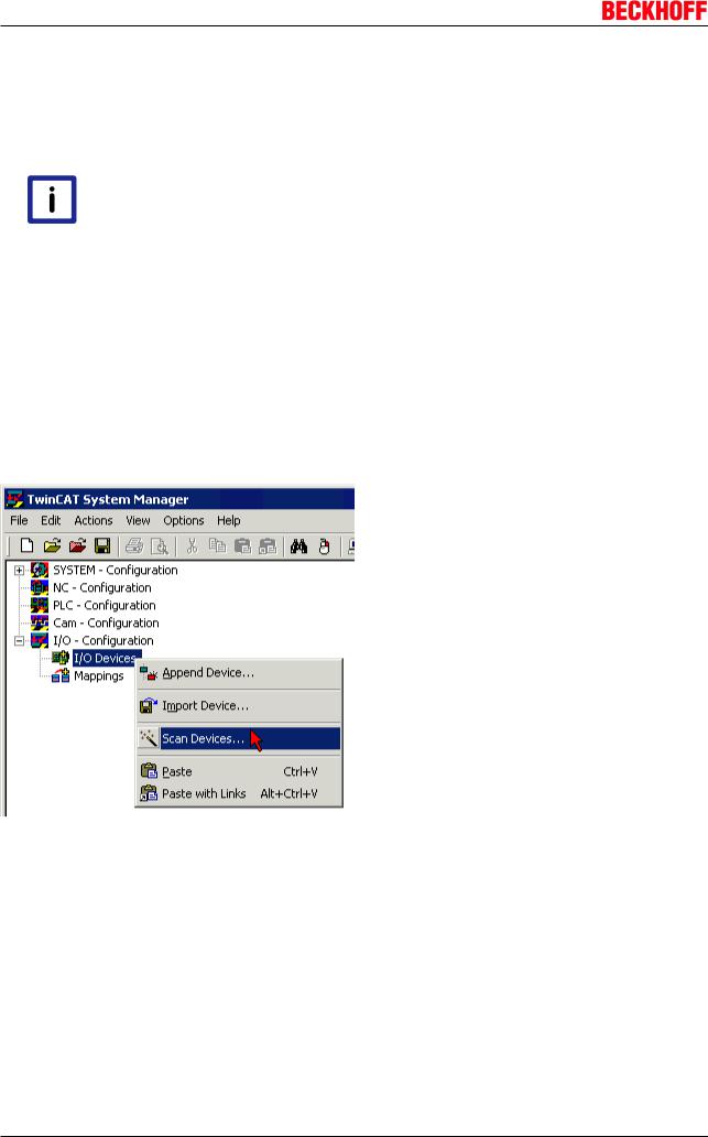
At the Beckhoff TwinCAT System Manager the configuration tree can be build in two different ways:
•by scanning [} 28] for existing hardware (called "online") and
•by manual inserting/appending [} 28] of fieldbus devices, couplers and slaves.
Automatic scanning in of the box
•The EtherCAT system must be in a safe, de-energized state before the EtherCAT modules are connected to the EtherCAT network!
•Switch on the operating voltage, open the TwinCAT System Manager [} 31] (Config mode), and scan in the devices (see Fig. 1). Acknowledge all dialogs with "OK", so that the configuration is in "FreeRun" mode.
Fig. 26: Scanning in the configuration (I/O Devices -> right-click -> Scan Devices...)
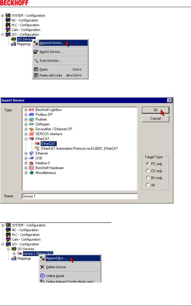
Appending a module manually
•The EtherCAT system must be in a safe, de-energized state before the EtherCAT modules are connected to the EtherCAT network!
•Switch on the operating voltage, open the TwinCAT System Manager [} 31] (Config mode)
•Append a new I/O device. In the dialog that appears select the device EtherCAT (Direct Mode), and confirm with OK.
28 |
Version 2.0.0 |
EP9214-0023 and EP9224-0023 |
Comissioning and Configuration
Fig. 27: Appending a new I/O device (I/O Devices -> right-click -> Append Device...)
Fig. 28: Selecting the device EtherCAT
• Append a new box.
Fig. 29: Appending a new box (Device -> right-click -> Append Box...)
• In the dialog that appears select the desired box (e.g. EP2816-0008), and confirm with OK.
EP9214-0023 and EP9224-0023 |
Version 2.0.0 |
29 |

Comissioning and Configuration
Fig. 30: Selecting a Box (e.g. EP2816-0008)
Fig. 31: Appended Box in the TwinCAT tree
30 Version 2.0.0 EP9214-0023 and EP9224-0023
Loading...