


C1120 S5 to II/O Lightbus Interface |
Beckhoff II/O-Lightbus System |
C1120
S5 to II/O-Lightbus Interface
Technical Documentation
VERSION 2.1
|
|
|
|
|
|
Date 27.06.97 |
Version 2.1 |
Page 1 of 52 |

C1120 S5 to II/O-Lightbus Interface |
Beckhoff II/O-Lightbus System |
|
Table of contents |
|
1 FUNCTIONAL DESCRIPTION OF HARDWARE |
..................................................................................... 3 |
|
2 FUNCTIONAL DESCRIPTION OF SOFTWARE ...................................................................................... |
4 |
|
2.1 |
Installation of Software ..................................................................................................................................... |
4 |
2.2 |
Main menu......................................................................................................................................................... |
5 |
2.3 |
Master Setup...................................................................................................................................................... |
7 |
|
C1120 Configuration ......................................................................................................................................... |
9 |
|
C1120 I/O Memory Map List .......................................................................................................................... |
13 |
|
Timer and Interrupts ........................................................................................................................................ |
19 |
|
C1100 to C1120 Project Conversion ............................................................................................................... |
21 |
|
Online Menu .................................................................................................................................................... |
22 |
|
Debug Menu .................................................................................................................................................... |
24 |
|
How to get started - setting up an I/O list ........................................................................................................ |
25 |
|
Status register S5 / C1120................................................................................................................................ |
26 |
|
Parallel Communication Channel .................................................................................................................... |
27 |
|
Table of error numbers: ................................................................................................................................... |
31 |
|
Service Routines in STEP 5 language.............................................................................................................. |
32 |
|
Status LEDs ..................................................................................................................................................... |
33 |
2.4 |
Slave Setup ...................................................................................................................................................... |
34 |
|
Edit Inputs ....................................................................................................................................................... |
36 |
|
Edit Outputs..................................................................................................................................................... |
37 |
|
Edit Configuration ........................................................................................................................................... |
38 |
|
Online Menu .................................................................................................................................................... |
40 |
2.5 |
Project Manager .............................................................................................................................................. |
42 |
2.6 |
System Configuration ...................................................................................................................................... |
44 |
|
System Entry.................................................................................................................................................... |
44 |
|
System ............................................................................................................................................................. |
45 |
|
Language ......................................................................................................................................................... |
46 |
|
Log File ........................................................................................................................................................... |
47 |
|
Program Parameter .......................................................................................................................................... |
48 |
3 C1120 INTERFACE: TECHNICAL DATA................................................................................................ |
49 |
|
4 |
INSTALLATION REMARKS...................................................................................................................... |
50 |
4.1 |
Assembly to the S5-PLC rack.......................................................................................................................... |
50 |
4.2 |
Connecting to a PC.......................................................................................................................................... |
50 |
|
System requirements ........................................................................................................................................ |
50 |
|
Interface ports for connection with a PC ......................................................................................................... |
51 |
5 C1120 SERIAL PORT PINOUT .................................................................................................................. |
52 |
|
Page 2 of 52 |
Version 2.1 |
Date 27.06.97 |
C1120 S5 to II/O Lightbus Interface |
Beckhoff II/O-Lightbus System |
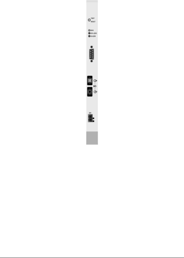
1 Functional description of Hardware
C1120
General
The interface card C1120 is an intelligent interface between the BECKHOFF II/O-Lightbus System and a SIEMENS SIMATIC S5 PLC. The SIEMENS PLC program is enabled to access binary and analog inputs and outputs of the II/O-Lightbus System via a Dual Ported RAM of the interface card. The I/O addresses of the II/O-Lightbus System are mapped to the S5 I/O address memory map with a configuration program running on a personal computer. The interface card C1120 is placed in a PLC slot for ‘intelligent peripherial devices’.
Date 27.06.97 |
Version 2.1 |
Page 3 of 52 |

C1120 S5 to II/O-Lightbus Interface |
Beckhoff II/O-Lightbus System |
2 Functional description of Software
For further documentation it is assumed that the interface card C1120 is connected to a PC running DOS with a serial interface cable to COMx.
2.1Installation of Software
First step: Backup copy of installation disc
Do not forget to backup your installation disc and use the backup copy instead of the original software disc.
-switch on your PC
-Use DISCCOPY to backup your installation disc
-Use your backup disc for the installation.
Installation to hard disc
1.switch on your PC
2.(generate and) change to your destination directory
3.insert the installation disc copy to floppy drive A:.
4.change to drive A:;
4.type: ’INSTALL C: <RETURN>’
The installation routine will copy all files to your destination directory of disc C: (or equiv.).
Start of program
start the C1120 setup program with ’PROGRAM <RETURN>’ from your destination directory of your PC.
Page 4 of 52 |
Version 2.1 |
Date 27.06.97 |
C1120 S5 to II/O Lightbus Interface |
Beckhoff II/O-Lightbus System |
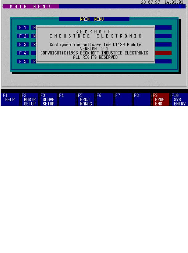
2.2Main menu
First screen after the start of program shows:
All actions are taken with the function keys F1 to F10. Some actions are provided with security questions. If the desired action is valid, type ‘J’ or ‘Y’ to activate, ‘N’ or ESC to quit. By choosing the key ESC you are able to return to the higher menu levels.
Function keys
F1 HELP
Shows a help text for the equivalent menu and function keys.
F2 MASTER SETUP
changes to the master setup menu to map the II/O Lightbus System addresses to the I/O addresses of the SIEMENS PLC.
F3 SLAVE SETUP
changes to slave setup
F5 PROJECT MANAGER
changes to the project manager menu to choose the working project from a list of (setup) projects.
Date 27.06.97 |
Version 2.1 |
Page 5 of 52 |

C1120 S5 to II/O-Lightbus Interface |
Beckhoff II/O-Lightbus System |
F9 PROGRAM END
returns to DOS after closing the application.
F10 SYSTEM ENTRY
changes to the setup menu of the running program.
Page 6 of 52 |
Version 2.1 |
Date 27.06.97 |
C1120 S5 to II/O Lightbus Interface |
Beckhoff II/O-Lightbus System |
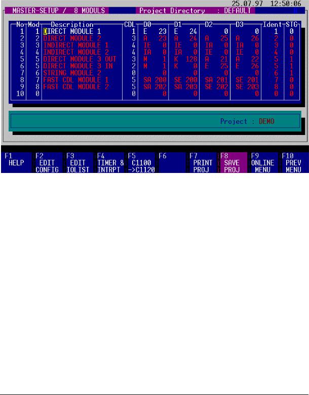
2.3Master Setup
The master setup menu is accessed by pressing F2 key from the main menu. With this menu, the address mapping between the II/O-Lightbus system and the SIEMENS PLC is displayed and can be edited, saved under a project name and transfered from and to the C1120 card.
The screen shows different fields for input, status line and function key setup.
Function keys:
F1 HELP
Shows a help text for the equivalent menu and function keys.
F2 EDIT CONFIGURATION
with this menu you can change the C1120 configuration.
F3 EDIT I/O LIST
with this menu you can modify the I/O address map list.
F4 TIMER & INTERRUPTS
with this menu you can configure the four fast fieldbus interrupts of the Beckhoff II/O Lightbus System.
Date 27.06.97 |
Version 2.1 |
Page 7 of 52 |

C1120 S5 to II/O-Lightbus Interface |
Beckhoff II/O-Lightbus System |
F5 C1100 -> C1120 |
|
with this menu projects of the Beckhoff C1100 card are converted to C1120 projects.
F7 PRINT I/O LIST
prints the I/O map to your printer on LPT1:.
F8 SAVE PROJECT
stores the setup of C1120 under a project name - if first time used you are asked for a project name. At further store commands, a <RETURN> stores under existing project name.
F9 ONLINE MENU
changes to the communication menu to exchange data with the C1120 card.
F10 PREVIOUS MENU
returns to the previous menu.
Page 8 of 52 |
Version 2.1 |
Date 27.06.97 |
C1120 S5 to II/O Lightbus Interface |
Beckhoff II/O-Lightbus System |
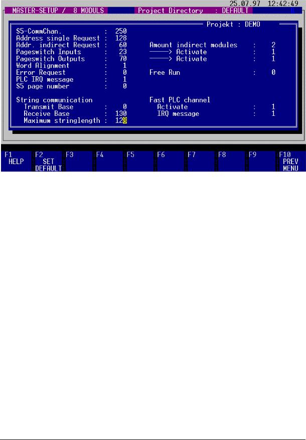
C1120 Configuration
with this menu you can change the C1120 configuration to setup all necessary parameters for the C1120 interface.
The field "S5-CommChannnel" describes the base address for the parallel channel functions (see chapter "parallel channel" ). For use of more than one C1120 cards in one PLC the base address default of 250 for the communication channel can be changed to an other address ( from address 128 - 250, length 6 Byte ). The address for status register will automatically change to input value +4 and the address for interrupt request will change to input value +5.
A single request is able to access an II/O Lightbus module directly without synchronized exchange with the process image (between read of input process image and output process image write)*, by use of the STEP 5 commands "Load I/O process peripherials" e.g. " Transfer I/O process peripherials ". Therefore, the base address "Address single request" of an address block for the single request is to be defined between 128 and 250. By setting a "0" for the base address "Address single request" the single request is disabled.
________________
* the PLC updates the Transfer Process Image automatically
Date 27.06.97 |
Version 2.1 |
Page 9 of 52 |

C1120 S5 to II/O-Lightbus Interface |
Beckhoff II/O-Lightbus System |
To enlarge the I/O address space, the use of "indirect modules" is available - a list of module data fields is stored in the C1120 RAM memory. The base address to exchange data with the Process image of the PLC is defined here (see equiv. chapter).
To obtain correct data for the PLC process image, the process image memory of the C1120 is divided in pages, which each by each are switched towards the PLC and towards the II/O Lightbus to refresh data contents. The pageswitch mechanism changes the memory pages to and from the PLC. The pageswitch inputs are defined as lowest address, the pageswitch outputs are defined as highest address by default.
By writing a "1" to the field "word alignment", the PLC is enabled to access the process image by word commands (16 bit - wise) The necessary selects are generated automatically. For use of more than one C1120, the word alignement can be disabled by overwriting a "0".
The default setup value of "0" in the field "Error request" enables the C1120 to stop the PLC with a timeout status of the C1120 in case errors occur on the II/O-Lightbus System, the C1120 interface deletes the I/O addresses in the Dual Ported RAM mapped to the PLC in case of error. By programming OB 23 and OB 28 the timeout can be managed by PLC software.
By setting the field value "Error request" to "1", the I/O addresses are not deleted in case of errors. The latest input data values are held in place, the writing of outputs data is confirmed, but writing is not executed, the error flag in the status byte is set.
IMPORTANT REMARK:
By use of option "1" the user has to achieve the check of the status byte error
flag in every PLC cycle to branch into a error routine, if the error flag is set.
After occurance of the error flag the fault number and number of modules can be read via the parallel communication channel. After return from the fault situation (repair of fiber optic media) a start of the II/O-Lightbus System can be forced by resetting the C1120 by software from the PLC.
In case of no success of the reset function, the error flag is set again, and as a return value of the function RESET-LWL the value of the initerror is returned (refer to chapter "Parellel communication channel").
Page 10 of 52 |
Version 2.1 |
Date 27.06.97 |
C1120 S5 to II/O Lightbus Interface |
Beckhoff II/O-Lightbus System |
By setting the "Free Run" option to "1" in the equivalent mask, the inputs of the II/O-Lightbus System are read asyncronously to the PLCprocess image at maximum II/O Lightbus communication refresh rate. The pageswitch mechanism displayes the newest process image memory page to the PLC.
Entering a “ 1” in the field PLC IRQ Frame causes the C1120 to send an extra control and interrupt message frame for triggering a local process image cycle on the intelligent peripheral modules. Those message frames are appended to the process data message frames.
The current page address of the C1120 is entered in the Page Number field.
String communication is used for communicating with intelligent peripheral modules. It can be used, among other things, for configuring the modules. The data packages (strings) are transmitted to the C1120 by way of the page frame.
The field Transmit Basis is for entering the page frame offset for the strings being sent. It should be noted that starting from the offset, 2 bytes are reserved for the handshake between PLC and C11220. The actual string is entered starting at the offset + 2.
The field Receive Basis is for entering the page frame offset for the strings being received. It should be noted that starting from the offset, 2 bytes are reserved for the handshake between PLC and C11220. The actual string is entered starting at the offset + 2.
The field Maximum String Length is for entering the maximum permissible length of the strings.
The purpose of the fast communications channel is for improved process synchronisation during multi-processor operation (see also “ Fast Communications Channel” ).
Entering a “ 1” in the Activate field enables the fast communications channel (see also “ Fast Communications Channel” ).
Entering a “ 1” in the field IRQ Frame causes the C1120 to send an extra control and interrupt message frame for triggering a local process image cycle on the intelligent peripheral modules assigned to the process channel. Those message frames are appended to the process data message frames.
Date 27.06.97 |
Version 2.1 |
Page 11 of 52 |

C1120 S5 to II/O-Lightbus Interface |
Beckhoff II/O-Lightbus System |
|
function keys |
|
|
F1 |
HELP |
|
|
displays help text. |
|
F2 |
SET DEFAULT |
|
|
sets configuration parameters to default. |
|
F10 |
PREVIOUS MENU |
|
|
returns to the master setup menu. |
|
IMPORTANT REMARK regarding the page number:
The page number for data exchange with the PLC is configurable, beginning with interface version numbers above V 1.51. Up to Version 1.51, the page number for data exchange is 0 by default.
Page 12 of 52 |
Version 2.1 |
Date 27.06.97 |

C1120 S5 to II/O Lightbus Interface |
Beckhoff II/O-Lightbus System |
C1120 I/O Memory Map List
All used II/O-Lightbus modules must be listed in the I/O list. The order of modules in the I/O list must reflect their physical position in the II/O-Lightbus System ring.
First step is to edit the I/O list:
Each new module is to be introduced to the list by pressing "F2": "Insert module". No actions take place during editing without adding a module as described. Addresses of existing modules can be edited and overwritten easily, modules can be deleted by pressing "F3". If a module is deleted, it has to be removed from the II/O-Lightbus System ring.
The coloumn "No" holds the actual line number. The coloumn "Mod" holds the corresponding module address. The coloumn "Msg" is without further use. The coloumn "Description" keeps a 20 character user description of the module name or function. The "CDL" - coloumn is used internally.
The address name of the SIEMENS PLC process image is entered in the fields "D0" to "D3". You can use any order or use addresses twice etc.
The coloumn "Ident" maps the indirect modules to their physical II/O-Lightbus address.
In the column “ STG” , those modules that are to be processed as part of the string communication are identified by a “ 1” . Those modules are similarly assigned to their physical module addresses by means of the Ident number.
Warning ! The interface card C1120 is not able to identify modules. If the I/O list and physical order of modules are different, or the inputs and outputs are set up incorrectly by DIP switches, I/O data is transferred erroneous from the PLC program to the modules without recognition.
Date 27.06.97 |
Version 2.1 |
Page 13 of 52 |

C1120 S5 to II/O-Lightbus Interface |
Beckhoff II/O-Lightbus System |
|
||
Function keys |
|
|
|
|
F1 |
HELP |
|
|
|
|
displays help text. |
|
|
|
F2 |
INSERT MODULE |
|
|
|
|
by pressing "F2" a new module is inserted at the current cursor position. The |
|
||
|
address is set to the equivalent line number. Following module addresses are |
|
||
|
incremented. After inserting a new module, description, I/O addresses and ident |
|
||
|
no. can be edited. Every line of the I/O list, containing a module number and I/O |
|
||
|
addresses, generates one telegram for II/O-Lightbus per PLC cycle. |
|
||
F3 |
CLEAR MODULE |
|
|
|
|
by pressing "F3" a line of the II/O setup is deleted. A confirmation is necessary |
|
||
|
for that action to take place. |
|
|
|
|
|
|
|
|
|
Warning ! |
In case of deleting a module from the I/O list, it is definitively |
|
|
|
|
necessary to remove the equivalent module from the II/O- |
|
|
|
|
Lightbus ring. Otherwise the II/O-Lightbus ring is incorrectly |
|
|
|
|
configured |
and is not ready to work. |
|
F4 INSERT ROW
If it is necessary to serve a module with more than one telegram per cycle, additional telegrams are generated by inserting a line to an existing module entry. In this case, the inserted line holds the same module number as the line before.
F10 PREVIOUS MENU
returns to the master setup menu.
Page 14 of 52 |
Version 2.1 |
Date 27.06.97 |

C1120 S5 to II/O Lightbus Interface |
Beckhoff II/O-Lightbus System |
Modules can be set up in the configuration list as:
-direct module or
-indirect module,
depending on the necessity of access in every PLC cycle. This is supplied to enlarge the address space of the PLC above 128 bytes process image.
Direct modules
Direct modules are mapped directly to the PLC process image. The PLC process image addresses are edited in the I/O byte addresses D0 to D3 of every telegram frame belonging to the module - each line in the setup screen belongs to a dedicated II/O-Lightbus telegram frame to the addressed module. The address names (e.g. O 10) of the PLC programm are used for reference.
Example given: the modules 1 and 2 are mapped as direct modules. The STEP5 program accesses the I/O addresses 23 to 26, the C1120 maps the I/O data to the modules 1 and 2:
IB 23, IB 24 |
from module 1 |
OB 23, OB 24, OB 25, OB 26 |
to module 2 |
The inputs and outputs can be addressed bit-, byte-, or wordwise:
I 23.0 ... I 23.7, oder IW 23 = IB 23 & IB 24
are handled as usual.
All direct mapped modules are refreshed synchronously and cyclic with the PLC cycle and process image refresh. The direct mapped modules can be accessed directly from the PLC program at any time.
The modules 7 and 8 are also direct modules. However, they are assigned to the fast communications channel by means of their identification codes “ SA” and “ SE” respectively.
If intelligent modules are to be addressed during the PLC cycle (e.g. terminal bus coupler) the first two data bytes (D0, D1) can be assigned constants. Those constants are entered with the identification codes “ M” (for memory) and “ C” (for constant).
In the example, D0 on module 5 is assigned the fixed value 1 (“ M” ) and D1 the fixed value 128 (“ C” ).
Date 27.06.97 |
Version 2.1 |
Page 15 of 52 |

C1120 S5 to II/O-Lightbus Interface |
Beckhoff II/O-Lightbus System |
Indirect modules
To enlarge the address space of the PLC system, modules can be mapped "indirectly":
they are accessed via a list of "indirect" communications, being addressed by a dedicated base address. These communications are processed in every PLC cycle. They can be used to enlarge the address space of 128 I/O Bytes of the PLC by placing the base address of the indirect communication list above 128. Another option is to change the contents of the I/O list cycle by cycle: a part of the II/O-Lightbus modules are mapped in a round robin way to the indirect I/O list to fit the total number of II/O Lightbus I/O bytes to the I/O address space of the PLC, with the effect, that those modules are being served only at occurence in the indirect communications list. One or more modules can be mapped to the indirect communications list. A single address block consists of the module address (IDENT number) and four bytes of I/O data. The reservation of memory space is done with the menu "Edit configuration": After definition of the base address of the indirect I/O list it is necessary to allocate 5 x (number of modules) Bytes list size: First byte contains the address number, following four bytes containing the I/O data. The list ends with a "0" found in an address byte location. These addresses are not available for standard I/O via PLC process image transfer. Address conflicts have to be avoided by the PLC programmer.
Arbitration of indirect modules
Indirect modules are listed in the I/O setup list, coloumn "D0 .. D3" with IE or IA, with address number 0. The choice of IE or IA is without use for the communication and only indicates the configuration of the II/O-Lightbus modules for input (IE) or output (EA).
By use of the indirect communications list every module in the II/O Lightbus System can be accessed, even the direct configured: Their IDENTnumber has to be placed in the first address block address location, following four bytes keep I/O data. By this, the module is accessed via the indirect communication mechanism. By replacing the IDENT number in the first location of the address block with "0", the indirect communication is skipped. If the programmer decides to address a direct module via indirect communication, the module is addressed twice by the II/O-Lightbus System.
Important! If inputs are read via indirect communication, the programmer has to regard that input informations are valid one cycle after the following. Outputs are written during the following cycle . This effect can be managed by using the statusbyte of the PLC (PB/PY 254): Bit 1 acts as life bit and changes status every cycle. By reading the life bit the programmer can recognize and count cycles (refer also to chapter "status register S5/C1120).
Example:
In above shown setup screen the modules 3 and 4 are mapped indirect. The base address for indirect communications list is set up to 60, number of indirect modules is 2. By this, 10 Bytes of address block space are available for the programmer: Byte 60 contains the IDENTnumber of module 3 (3), the bytes 61 to 64 are I/O data for module 3. Address 65 keeps the IDENT number of module 4 (4), bytes 66 to 69 are I/O data for module 4. Byte 70 is available for standard or direct I/O.
Page 16 of 52 |
Version 2.1 |
Date 27.06.97 |
 Loading...