


CB3053
Table of contents
 Loading...
CB3053
Manual
rev. 1.2
Beckhoff Automation GmbH phone: +49 (0) 52 46/963-0
Eiserstr. 5 fax: +49 (0) 52 46/963-198
33415 Verl email: info@beckhoff.de
Germany web: www.beckhoff.de


Contents
Contents
0 Document History ................................................................................................................................. 5
1 Introduction ........................................................................................................................................... 6
1.1 Notes on the Documentation ......................................................................................................... 6
1.1.1 Liability Conditions ................................................................................................................ 6
1.1.2 Copyright ............................................................................................................................... 6
1.2 Safety Instructions ......................................................................................................................... 7
1.2.1 Disclaimer .............................................................................................................................. 7
1.2.2 Description of Safety Symbols .............................................................................................. 7
1.3 Essential Safety Measures ............................................................................................................ 8
1.3.1 Operator's Obligation to Exercise Diligence .......................................................................... 8
1.3.2 National Regulations Depending on the Machine Type ........................................................ 8
1.3.3 Operator Requirements ......................................................................................................... 8
1.4 Functional Range .......................................................................................................................... 9
2 Overview ............................................................................................................................................. 10
2.1 Features ...................................................................................................................................... 10
2.2 Specifications and Documents .................................................................................................... 12
3 Detailed Description ........................................................................................................................... 13
3.1 Power Supply / UPS .................................................................................................................... 13
3.2 CPU ............................................................................................................................................. 13
3.3 Memory ....................................................................................................................................... 13
4 Connectors ......................................................................................................................................... 14
4.1 Connector Map ............................................................................................................................ 15
4.2 Power Supply .............................................................................................................................. 16
4.3 Power Connector ......................................................................................................................... 17
4.4 System ........................................................................................................................................ 18
4.5 External CMOS Battery ............................................................................................................... 19
4.6 Memory ....................................................................................................................................... 20
4.7 DVI............................................................................................................................................... 23
4.8 LVDS ........................................................................................................................................... 24
4.9 Touch Screen .............................................................................................................................. 26
4.10 USB 1-4 ....................................................................................................................................... 27
4.11 USB 5-8 ....................................................................................................................................... 28
4.12 LAN.............................................................................................................................................. 29
4.13 Audio ........................................................................................................................................... 30
4.14 IDE Interface ............................................................................................................................... 31
4.15 Serial Interfaces COM1 and COM2 ............................................................................................ 32
4.16 SMB/I2C ...................................................................................................................................... 33
4.17 Mini-PCI ....................................................................................................................................... 34
4.18 Fan Connector ............................................................................................................................. 36
5 BIOS Settings ..................................................................................................................................... 37
5.1 Remarks for Setup Use ............................................................................................................... 37
5.2 Top Level Menu ........................................................................................................................... 37
5.3 Standard CMOS Features ........................................................................................................... 38
5.3.1 IDE Channel 0 Master/Slave ............................................................................................... 39
5.4 Advanced BIOS Features ........................................................................................................... 40
5.4.1 CPU Feature ....................................................................................................................... 42
Beckhoff New Automation Technology CB3053 page 3

Contents
5.4.2 Hard Disk Boot Priority ........................................................................................................ 43
5.5 Advanced Chipset Features ........................................................................................................ 44
5.6 Integrated Peripherals ................................................................................................................. 45
5.6.1 OnChip IDE Devices ........................................................................................................... 46
5.6.2 Onboard Devices ................................................................................................................. 47
5.6.3 SuperIO Devices ................................................................................................................. 48
5.6.4 USB Device Setting ............................................................................................................. 49
5.7 Power Management Setup .......................................................................................................... 50
5.7.1 HPET Feature ..................................................................................................................... 51
5.7.2 Intel DTS Feature ................................................................................................................ 52
5.8 PnP/PCI Configuration ................................................................................................................ 53
5.8.1 IRQ Resources .................................................................................................................... 54
5.9 PC Health Status ......................................................................................................................... 55
5.10 Load Fail-Safe Defaults ............................................................................................................... 57
5.11 Load Optimized Defaults ............................................................................................................. 57
5.12 Set Password .............................................................................................................................. 57
5.13 Save & Exit Setup ....................................................................................................................... 57
5.14 Exit Without Saving ..................................................................................................................... 57
6 BIOS update ....................................................................................................................................... 58
7 Mechanical Drawing ........................................................................................................................... 59
7.1 PCB: Mounting Holes .................................................................................................................. 59
7.2 PCB: Pin 1 Dimensions ............................................................................................................... 60
7.3 PCB: Die Center .......................................................................................................................... 61
8 Technical Data .................................................................................................................................... 62
8.1 Electrical Data ............................................................................................................................. 62
8.2 Environmental Conditions ........................................................................................................... 62
8.3 Thermal Specifications ................................................................................................................ 63
9 Support and Service ........................................................................................................................... 64
9.1 Beckhoff's Branch Offices and Representatives ......................................................................... 64
9.2 Beckhoff Headquarters................................................................................................................ 64
9.2.1 Beckhoff Support ................................................................................................................. 64
9.2.2 Beckhoff Service ................................................................................................................. 64
I Annex: Post-Codes ............................................................................................................................. 65
II Annex: Resources .............................................................................................................................. 68
A IO Range ......................................................................................................................................... 68
B Memory Range ................................................................................................................................ 68
C Interrupt ........................................................................................................................................... 68
D PCI Devices ..................................................................................................................................... 69
E SMB Devices ................................................................................................................................... 69
page 4 Beckhoff New Automation Technology CB3053

Notes on the Documentation Chapter: Document History
0 Document History
Version Changes
0.1 first pre-release
1.0 added dimensional drawings
1.1 added maximum current on 2x3 connector, no more TTL option for COM, updated
block diagram (ALC885 EOL), minor changes
1.2 improved output quality of dimensional drawings, minor changes
NOTE
All company names, brand names, and product names referred to in this manual are registered or
unregistered trademarks of their respective holders and are, as such, protected by national and
international law.
Beckhoff New Automation Technology CB3053 page 5

Chapter: Introduction Notes on the Documentation
1 Introduction
1.1 Notes on the Documentation
This description is only intended for the use of trained specialists in control and automation engineering
who are familiar with the applicable national standards. It is essential that the following notes and
explanations are followed when installing and commissioning these components.
1.1.1 Liability Conditions
The responsible staff must ensure that the application or use of the products described satisfy all the
requirements for safety, including all the relevant laws, regulations, guidelines and standards.
The documentation has been prepared with care. The products described are, however, constantly under
development. For that reason the documentation is not in every case checked for consistency with
performance data, standards or other characteristics. None of the statements of this manual represents a
guarantee (Garantie) in the meaning of § 443 BGB of the German Civil Code or a statement about the
contractually expected fitness for a particular purpose in the meaning of § 434 par. 1 sentence 1 BGB. In
the event that it contains technical or editorial errors, we retain the right to make alterations at any time
and without warning. No claims for the modification of products that have already been supplied may be
made on the basis of the data, diagrams and descriptions in this documentation.
1.1.2 Copyright
© This documentation is copyrighted. Any reproduction or third party use of this publication, whether in
whole or in part, without the written permission of Beckhoff Automation GmbH, is forbidden.
page 6 Beckhoff New Automation Technology CB3053
Safety Instructions Chapter: Introduction
1.2 Safety Instructions
Please consider the following safety instructions and descriptions. Product specific safety instructions are
to be found on the following pages or in the areas mounting, wiring, commissioning etc.
1.2.1 Disclaimer
All the components are supplied in particular hardware and software configurations appropriate for the
application. Modifications to hardware or software configurations other than those described in the
documentation are not permitted, and nullify the liability of Beckhoff Automation GmbH.
1.2.2 Description of Safety Symbols
The following safety symbols are used in this documentation. They are intended to alert the reader to the
associated safety instructions.
ACUTE RISK OF INJURY!
If you do not adhere to the safety advise next to this symbol, there is immediate danger to life and health
of individuals!
RISK OF INJURY!
If you do not adhere to the safety advise next to this symbol, there is danger to life and health of
individuals!
HAZARD TO INDIVIDUALS, ENVIRONMENT, DEVICES, OR DATA!
If you do not adhere to the safety advise next to this symbol, there is obvious hazard to individuals, to
environment, to materials, or to data.
NOTE OR POINTER
This symbol indicates information that contributes to better understanding.
Beckhoff New Automation Technology CB3053 page 7

Chapter: Introduction Essential Safety Measures
1.3 Essential Safety Measures
1.3.1 Operator's Obligation to Exercise Diligence
The operator must ensure that
o the product is only used for its intended purpose
o the product is only operated in sound condition and in working order
o the instruction manual is in good condition and complete, and always available for reference at the
location where the products are used
o the product is only used by suitably qualified and authorised personnel
o the personnel is instructed regularly about relevant occupational safety and environmental protection
aspects
o the operating personnel is familiar with the operating manual and in particular the safety notes
contained herein
1.3.2 National Regulations Depending on the Machine Type
Depending on the type of machine and plant in which the product is used, national regulations governing
the controllers of such machines will apply, and must be observed by the operator. These regulations
cover, amongst other things, the intervals between inspections of the controller. The operator must initiate
such inspections in good time.
1.3.3 Operator Requirements
o Read the operating instructions
All users of the product must have read the operating instructions for the system they work with.
o System know-how
All users must be familiar with all accessible functions of the product.
page 8 Beckhoff New Automation Technology CB3053

Functional Range Chapter: Introduction
1.4 Functional Range
NOTE
The descriptions contained in the present documentation represent a detailed and extensive product
description. As far as the described motherboard was acquired as an integral component of an Industrial
PC from Beckhoff Automation GmbH, this product description shall be applied only in limited scope. Only
the contractually agreed specifications of the corresponding Industrial PC from Beckhoff Automation
GmbH shall be relevant. Due to several models of Industrial PCs, variations in the component placement
of the motherboards are possible. Support and service benefits for the built-in motherboard will be
rendered by Beckhoff Automation GmbH exclusively as specified in the product description (inclusive
operation system) of the particular Industrial PC.
Beckhoff New Automation Technology CB3053 page 9
Chapter: Overview Features
2 Overview
2.1 Features
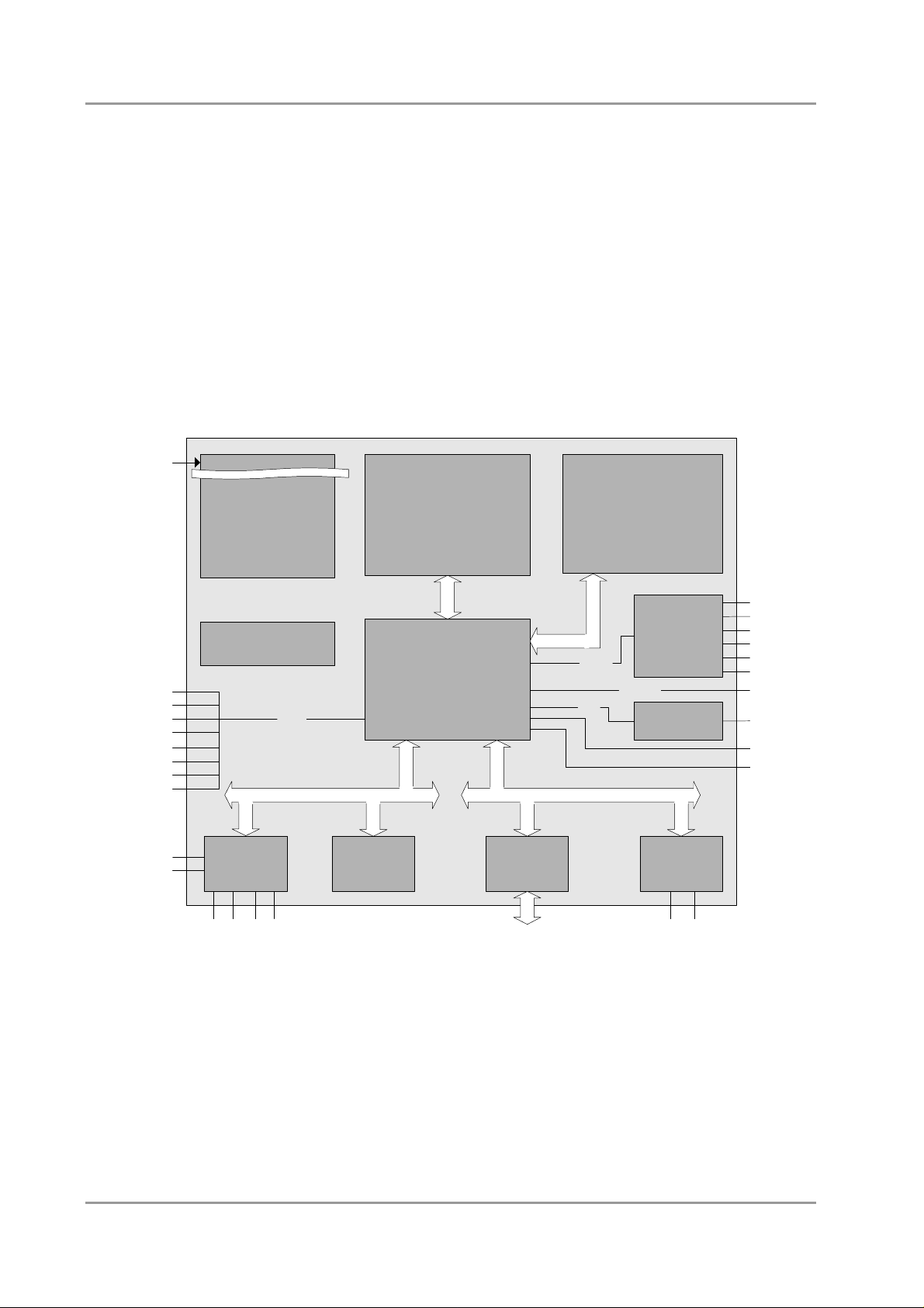
The CB3053 is a highly complex 3,5-inch board which incorporates complete motherboard functionality.
Equipped with an Intel® Atom™ processor (Z510 or Z530), it can accommodate up to 2 GByte of RAM
(DDR2-533) via SO-DIMM200. It also provides a PCI bus (via mPCI connector) and additional peripheral
devices such as two serial interfaces, two Gigabit Ethernet interfaces (LAN), an IDE interface, an audio
interface (HDA 5.1), eight USB channels, DVI and LVDS/TFT support, and a touchscreen connector. The
board is based on Intel®'s Menlow® platform which is optimized for low power consumption. Relieving
system designers of the burden that the need for active cooling normally presents, Menlow® offers
attractive new possibilities in the embedded and mobile markets. As a special feature, the board provides
either an internal (capacitor-based) or an external (Pb-battery) UPS device.
24V
USB1
USB2
USB3
USB4
USB5
USB6
USB7
USB8
KB
MS
galvanically isolated
UPS: Pb-Batt or
UPS: Capacitors
Power DC/DC
(VCCCore; VTT;
DDRVTT
1,5V; 1,8V; 2,5V; 3,3V)
Clock
SL28610BLC
USB 2.0
Winbond®
W83627HG
LPC
Intel® Atom™ CPU
Z510 / Z530
(1.1 GHz / 1.6 GHz)
HOST
Intel® SCH
US15W Chipset
BIOS
MEMORY
Pericom®
PI7C9X110
PCIe-to-PCI
PCI
1x SODIMM200
DDR2-RAM
(400/533MHz)
RealTek®
HDA-Link
LVDS 18/24
SDVO
PCIe
SDVO-to-DVI
(CH7307C)
ALC889
Intel®
82575EB
SPDIF i
SPDIF o
LINE IN
LINE OUT
MIC
AUX
LCD
DVI
IDE
SMBus
FAN
COM1
COM2
Watchdog
mPCI
LAN 1
LAN 2
o Processor Intel® Atom™ (single core, 512KB L2-cache, up to 1.6 GHz clock speed)
o Chipset Intel® SCH US15W with integrated graphics adapter
o SO-DIMM200 socket for one DDR2-533 module of up to 2 GByte
o Two serial interfaces COM1 and COM2
o Two LAN interfaces Ethernet 10/100/1000 (Base-T)
o IDE interface
o PS2 keyboard / mouse interface
o Eight USB 2.0 interfaces
page 10 Beckhoff New Automation Technology CB3053

Features Chapter: Overview
o AWARD BIOS 6.10
o DVI connection
o LCD connection via LVDS 18/24Bit
o AC97/HDA compatible sound controller with SPDIF in and out
o RTC with external CMOS battery
o 24V supply voltage (tolerates 20V-30V)
o PCI bus via mPCI connector
o UPS: capacitor-based or Pb-battery
o sizet: 102 mm x 147 mm
Beckhoff New Automation Technology CB3053 page 11

Chapter: Overview Specifications and Documents
2.2 Specifications and Documents
In making this manual and for further reading of technical documentation, the following documents,
specifications and web-pages were used and are recommended.
§ PCI Specification
Version 2.3 resp. 3.0
www.pcisig.com
§ ACPI Specification
Version 3.0
www.acpi.info
§ ATA/ATAPI Specification
Version 7 Rev. 1
www.t13.org
§ USB Specifications
www.usb.org
§ SM-Bus Specification
Version 2.0
www.smbus.org
§ Intel® Chipset Documentation
SCH Datasheet
www.intel.com
§ Intel® Chip Documentation
Atom Datasheet
www.intel.com
§ Winbond® Chip Documentation
W83627HG
www.winbond-usa.com oder www.winbond.com.tw
§ Intel® Chip Documentation
82575EB Datasheet
www.intel.com
page 12 Beckhoff New Automation Technology CB3053

Power Supply / UPS Chapter: Detailed Description
3 Detailed Description
3.1 Power Supply / UPS
The CB3053 needs an external power supply of 24V (will tolerate 20V-30V). This input is galvanically
isolated from the board's internal circuitry. It is also used for charging any UPS device that may be
present. This UPS device is either capacitor-based or connected externally as a Pb-battery pack. With a
UPS installed and charged, the module can stay operational even when a power failure occurs. A
capacitor-based UPS can keep the board alive only for a few seconds while a Pb-battery typically allows
for several minutes of continued operation. The exact amount of time is hard to predict as it also depends
on factors such as the UPS' charge level at the time of the power failure, CPU/chipset power consumption
etc. Generally, a Pb-battery needs a much longer time to reach full charge level compared to a
capacitor-based UPS.
3.2 CPU
The motherboard employs an Intel® Atom™ processor either with 1.1GHz or with 1.6GHz clock speed
(Z510/Z530). These are single core CPUs which are optimized for low power consumption while at the
same time providing state-of-the-art computing performance.
The processors include a second level cache of 512 KByte. They also offer many features known from
the desktop range such as MMX2, serial number, loadable microcode etc.
The Atom™ CPU is combined with the SCH US15W chipset. The power consumption of these two
components never exceeds 5 watts combined. Therefore, passive cooling solutions will be sufficient for
many system configurations.
3.3 Memory
There is one conventional SO-DIMM200 socket available to equip the board with memory. For technical
and mechanical reasons it is possible that particular memory modules cannot be employed. Please ask
your sales representative for recommended memory modules.
With currently available SO-DIMM200 modules a memory extension up to 2 GByte is possible
(DDR2-533).
Beckhoff New Automation Technology CB3053 page 13

Chapter: Connectors Memory
4 Connectors
This section describes all the connectors found on the CB3053.
CAUTION
For most interfaces, the cables must meet certain requirements. For instance, USB 2.0 requires twisted
and shielded cables to reliably maintain full speed data rates. Restrictions on maximum cable length are
also in place for many high speed interfaces and for power supply. Please refer to the respective
specifications and use suitable cables at all times.
page 14 Beckhoff New Automation Technology CB3053
Connector Map Chapter: Connectors
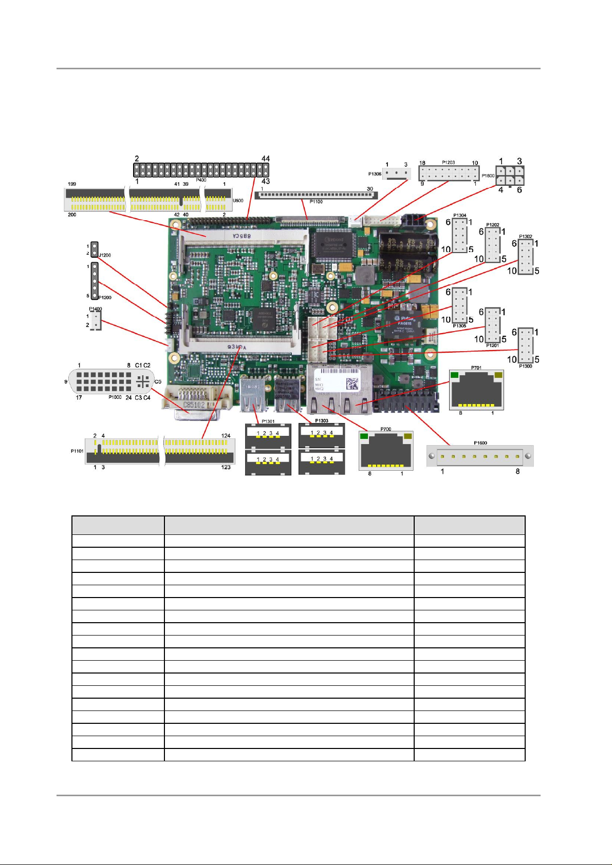
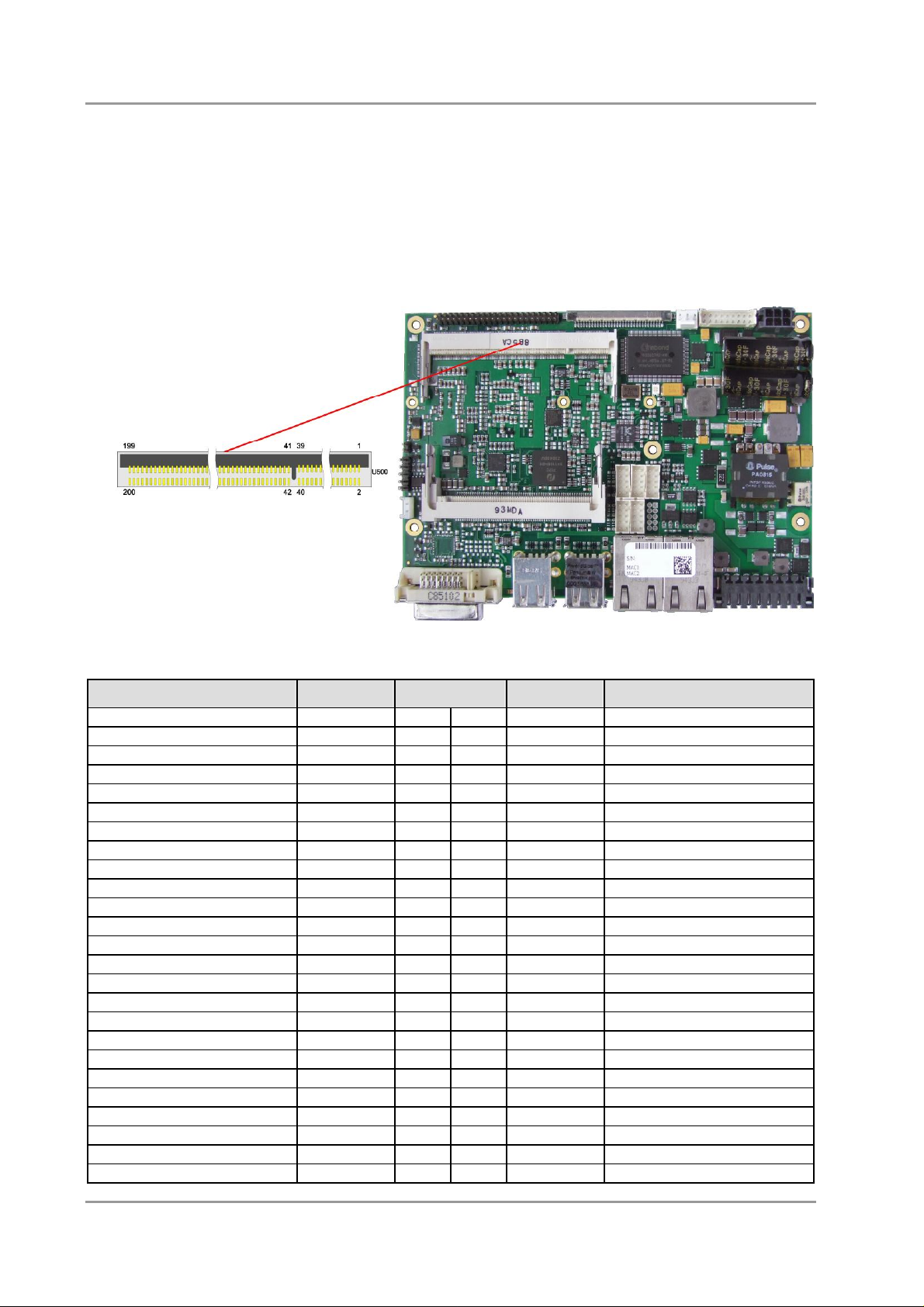
4.1 Connector Map
Please use the connector map below for quick reference. Only connectors on the component side are
shown. For more information on each connector refer to the table below.
Ref-No. Function Page
P400 "IDE Interface" p. 31
U500 "Memory" p. 20
P700/1 "LAN" p. 29
P1000 "DVI" p. 23
P1100 "LVDS" p. 24
P1101 "Mini-PCI" p. 34
P1200 "Touch Screen" p. 26
J1200 "Touch Screen" p. 26
P1201 "SMB/I2C" p. 33
P1202 "Audio" p. 30
P1203 "System" p. 18
P1300/2 "Serial Interfaces COM1 and COM2" p. 32
P1301/3 "USB 1-4" p. 27
P1304/5 "USB 5-8" p. 28
P1306 "Fan Connector" p. 36
P1400 "External CMOS Battery" p. 19
P1600 "Power Supply" p. 16
P1800 "Power Connector" p. 17
Beckhoff New Automation Technology CB3053 page 15
Chapter: Connectors Power Supply
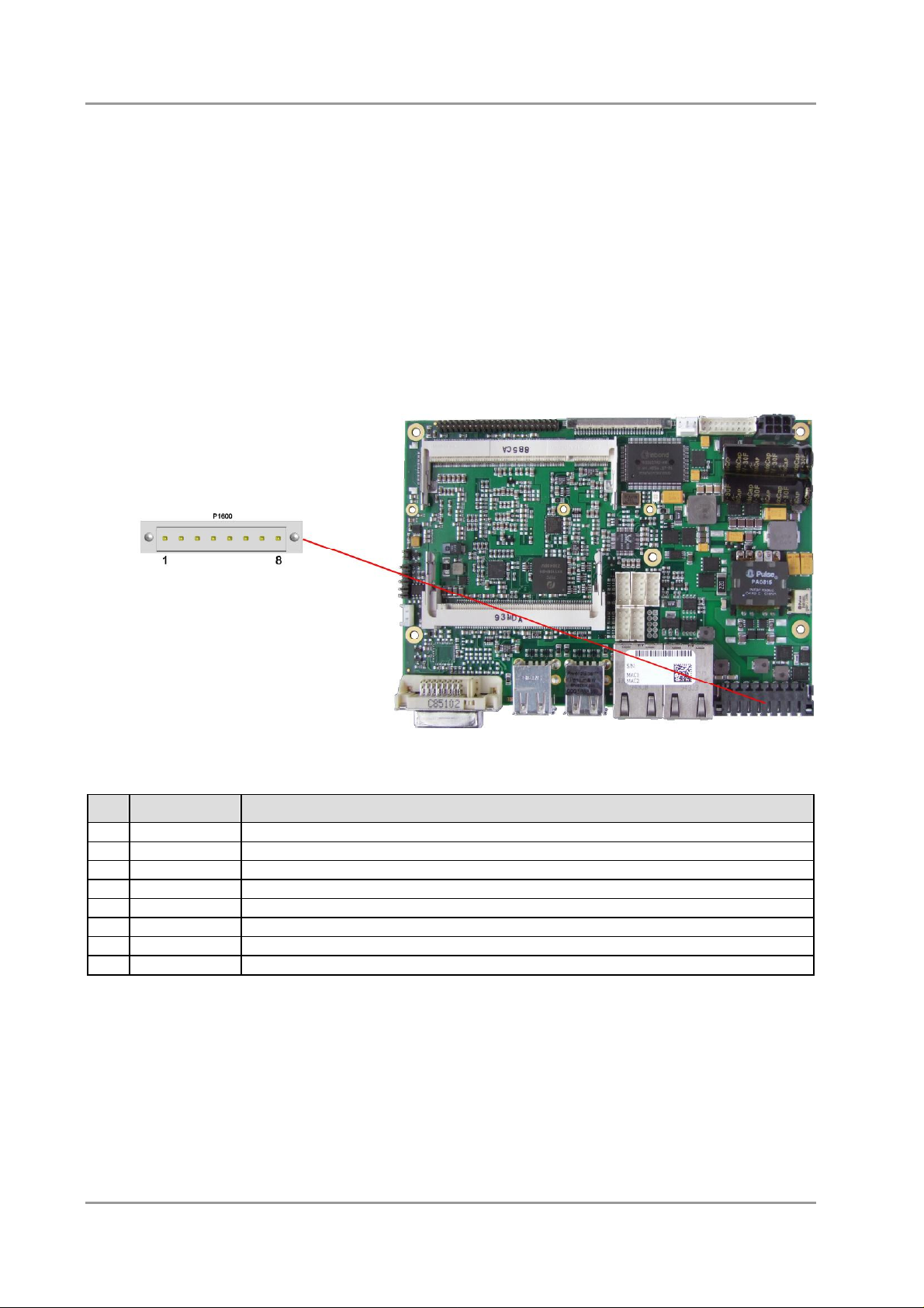
4.2 Power Supply
The power supply of the hardware module is realized via an 8pin connector (Weidmüller 180537-0000).
The main 24V power lines are assigned to pins 5 and 6. An external Pb-battery can be connected to pins
1 and 2 to provide UPS functionality. Contact your sales person to discuss suitable battery packs.
Pin 3 (UPS_OUT) is a 24V output (max. 2A), which is supported by the UPS (Pb-accu or capacitors) in
the event of a power failure. One possible application would be to use this output to supply a display
device which would then be able to display information about the power failure and the pending system
shutdown.
If a UPS is present you need to have a possibility to shutdown the board in a regular way without
activating the UPS, thereby preventing premature aging of UPS components. That's what pin 7
(PC_ON#) is for. When pulled high (24V) a regular shutdown without UPS activity is triggered. As a part
of this regular shutdown pins 3 (UPS_OUT) and 8 (Power Status) are pulled from 24V to 0V. Any devices
connected to UPS_OUT will thus also be switched off without discharging the UPS.
pinout power connector:
Pin
Name Description
1 BATT24V# Pb-accu 24V 2 BATT24V Pb-accu 24V +
3 UPS_OUT UPS outgoing supply 24V
4 GND ground
5 24V# power supply 24V 6 24V power supply 24V +
7 PC_ON# power on
8 PWRSTAT power status
page 16 Beckhoff New Automation Technology CB3053
Power Connector Chapter: Connectors
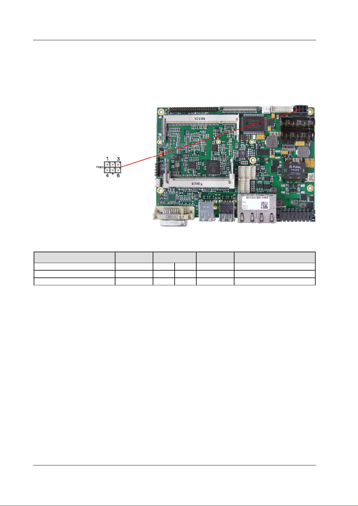
4.3 Power Connector
The board is equipped with a 2x3pin Molex connector offering standard 5V and 12V power supplies for
additional peripheral devices. Maximum current is 2 amperes for VCC/SVCC combined, and also 2
amperes for 12V. In the case of a power failure theses supplies are supported by the UPS circuit, but only
if the UPS is a Pb-battery. They are not supported if the UPS is capacitor-based.
pinout power connector Molex 2x3:
Description Name Pin Name Description
ground GND 1 4 VCC power supply 5V
reserved RES 2 5 SVCC standby supply 5V
reserved RES 3 6 12V power supply 12V
Beckhoff New Automation Technology CB3053 page 17
Chapter: Connectors System
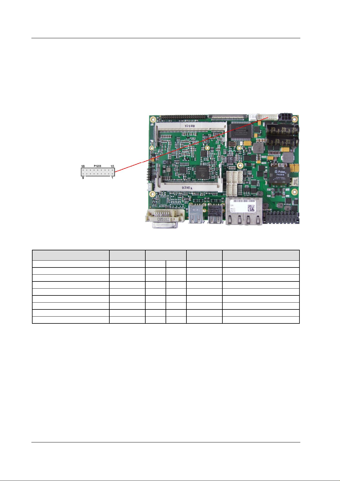
4.4 System
Some typical signals for system control are provided through a 2x9 pin connector (JST B18B-PHDSS,
mating connector: PHDR-18VS). This connector combines signals for power button, reset, keyboard,
speaker, and several LEDs such as harddisk LED, touch screen LED, suspend LED, and three additional
LEDs which are driven by GPIOs. Of these three GPIO-LEDs, LED1 and LED2 are already provided with
a series resistor. As can be seen from the pinout table below, corresponding signals are often placed
vis-à-vis or at least near to each other.
Description Name Pin Name Description
ground GND 1 10 PWRBTN# on/suspend button
ground GND 2 11 RESET# reset to ground
LED touch screen TOUCHLED 3 12 3.3V 3.3 volt supply
LED suspend / ACPI S-LED 4 13 S3.3V standby supply 3.3 volt
LED harddisk HDLED 5 14 3.3V 3.3 volt supply
LED GPIO device LED1 6 15 3.3V 3.3 volt supply
LED GPIO device LED2 7 16 LED3 LED GPIO device
speaker to 5 volt SPEAKER 8 17 KDAT keyboard data
standby supply 5 volt (S)VCC 9 18 KCLK keyboard clock
page 18 Beckhoff New Automation Technology CB3053
External CMOS Battery Chapter: Connectors
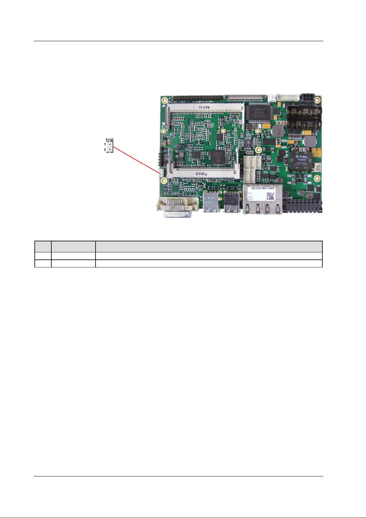
4.5 External CMOS Battery
For keeping the internal clock alive even if the rest of the board is switched off, an external battery can be
attached via a 2 pin connector (JST B2B-EH-A, mating connector: EHR-2).
Pin
Name Description
1 BATT battery 3.3 volt
2 GND ground
Beckhoff New Automation Technology CB3053 page 19
Chapter: Connectors Memory
4.6 Memory
Conventional SO-DIMM200 memory modules, as familiar from notebook computers, are used to equip
the board with memory. For technical and mechanical reasons it is possible that particular memory
modules cannot be employed. Please ask your distributor for recommended memory modules.
With currently available SO-DIMM200 modules a memory extension up to 2 GByte is possible
(DDR2-533).
All timing parameters for different memory modules are automatically set by BIOS.
Description Name Pin Name Description
memory reference current REF 1 2 GND ground
ground GND 3 4 DQ4 data 4
data 0 DQ0 5 6 DQ5 data 5
data 1 DQ1 7 8 GND ground
ground GND 9 10 DQM0 data mask 0
data strobe 0 - DQS0# 11 12 GND ground
data strobe 0 + DQS0 13 14 DQ6 data 6
ground GND 15 16 DQ7 data 7
data 2 DQ2 17 18 GND ground
data 3 DQ3 19 20 DQ12 data 12
ground GND 21 22 DQ13 data 13
data 8 DQ8 23 24 GND ground
data 9 DQ9 25 26 DQM1 data mask 1
ground GND 27 28 GND ground
data strobe 1 - DQS1# 29 30 CK0 clock 0 +
data strobe 1 + DQS1 31 32 CK0# clock 0 ground GND 33 34 GND ground
data 10 DQ10 35 36 DQ14 data 14
data 11 DQ11 37 38 DQ15 data 15
ground GND 39 40 GND ground
ground GND 41 42 GND ground
data 16 DQ16 43 44 DQ20 data 20
data 17 DQ17 45 46 DQ21 data 21
ground GND 47 48 GND ground
data strobe 2 - DQS2# 49 50 N/C reserved
page 20 Beckhoff New Automation Technology CB3053

Memory Chapter: Connectors
Description Name Pin Name Description
data strobe 2 + DQS2 51 52 DQM2 data mask 2
ground GND 53 54 GND ground
data 18 DQ18 55 56 DQ22 data 22
data 19 DQ19 57 58 DQ23 data 23
ground GND 59 60 GND ground
data 24 DQ24 61 62 DQ28 data 28
data 25 DQ25 63 64 DQ29 data 29
ground GND 65 66 GND ground
data mask 3 DQM3 67 68 DQS3# data strobe 3 reserved N/C 69 70 DQS3 data strobe 3 +
ground GND 71 72 GND ground
data 26 DQ26 73 74 DQ30 data 30
data 27 DQ27 75 76 DQ31 data 31
ground GND 77 78 GND ground
clock enables 0 CKE0 79 80 CKE1 clock enables 1
1.8 volt supply 1.8V 81 82 1.8V 1.8 volt supply
reserved N/C 83 84 N/C reserved
SDRAM bank 2 BA2 85 86 N/C reserved
1.8 volt supply 1.8V 87 88 1.8V 1.8 volt supply
address 12 A12 89 90 A11 address 11
address 9 A9 91 92 A7 address 7
address 8 A8 93 94 A6 address 6
1.8 volt supply 1.8V 95 96 1.8V 1.8 volt supply
address 5 A5 97 98 A4 address 4
address 3 A3 99 100 A12 address 2
address 1 A1 101 102 A0 address 0
1.8 volt supply 1.8V 103 104 1.8V 1.8 volt supply
address 10 A10 105 106 BA1 SDRAM bank 1
SDRAM bank 0 BA0 107 108 RAS# row address strobe
write enable WE# 109 110 S0# chip select 0
1.8 volt supply 1.8V 111 112 1.8V 1.8 volt supply
column address strobe CAS# 113 114 ODT0 on die termination 0
chip select 1 S1# 115 116 A13 address 13
1.8 volt supply 1.8V 117 118 1.8V 1.8 volt supply
on die termination 1 ODT1 119 120 N/C reserved
ground GND 121 122 GND ground
data 32 DQ32 123 124 DQ36 data 36
data 33 DQ33 125 126 DQ37 data 37
ground GND 127 128 GND ground
data strobe 4 - DQS4# 129 130 DQM4 data mask 4
data strobe 4 + DQS4 131 132 GND ground
ground GND 133 134 DQ38 data 38
data 34 DQ34 135 136 DQ39 data 39
data 35 DQ35 137 138 GND ground
ground GND 139 140 DQ44 data 44
data 40 DQ40 141 142 DQ45 data 45
data 41 DQ41 143 144 GND ground
ground GND 145 146 DQS5# data strobe 5 data mask 5 DQM5 147 148 DQS5 data strobe 5 +
ground GND 149 150 GND ground
data 42 DQ42 151 152 DQ46 data 46
data 43 DQ43 153 154 DQ47 data 47
ground GND 155 156 GND ground
data 48 DQ48 157 158 DQ52 data 52
data 49 DQ49 159 160 DQ53 data 53
Beckhoff New Automation Technology CB3053 page 21
Loading...