


 Loading...
Documentation
EL9xxx
EtherCAT System Terminals
Version |
3.1 |
Date |
06.04.2015 |

|
|
Table of contents |
|
Table of contents |
|
||
1 Overview EtherCAT System and Function terminals............................................................................. |
5 |
||
2 |
Foreword .................................................................................................................................................... |
6 |
|
|
2.1 |
Notes on the documentation............................................................................................................. |
6 |
|
2.2 |
Safety instructions ............................................................................................................................ |
7 |
|
2.3 |
Documentation issue status.............................................................................................................. |
8 |
|
2.4 |
Version identification of EtherCAT devices....................................................................................... |
9 |
3 |
Product overview..................................................................................................................................... |
13 |
|
|
3.1 |
EL9011, EL9080 ............................................................................................................................. |
13 |
|
|
3.1.1 EL9011, EL9080 Introduction and Technical Data ........................................................... |
13 |
|
3.2 |
EL9070 ........................................................................................................................................... |
15 |
|
|
3.2.1 EL9070 Introduction and Technical Data.......................................................................... |
15 |
|
3.3 |
EL9100, EL9110, EL9190............................................................................................................... |
17 |
|
|
3.3.1 EL9100, EL9110, EL9190 Introduction and Technical Data ............................................ |
17 |
|
3.4 |
EL9150, EL9160 ............................................................................................................................. |
21 |
|
|
3.4.1 EL9150, EL9160 Introduction and Technical Data .......................................................... |
21 |
|
3.5 |
EL9181, EL9182, EL9183............................................................................................................... |
24 |
|
|
3.5.1 EL9181, EL9182, EL9183 Introduction and Technical Data............................................. |
24 |
|
3.6 |
EL9184, EL9186, EL9187, EL9188, EL9189.................................................................................. |
27 |
|
|
3.6.1 EL9184, EL9186, EL9187, EL9188, EL9189 Introduction and Technical Data ................ |
27 |
|
3.7 |
EL9195 ........................................................................................................................................... |
33 |
|
|
3.7.1 EL9195 Introduction and Technical Data.......................................................................... |
33 |
|
3.8 |
EL9200, EL9210, EL9290............................................................................................................... |
35 |
|
|
3.8.1 EL9200, EL9210, EL9290 Introduction and Technical Data............................................. |
35 |
|
3.9 |
EL9250, EL9260 ............................................................................................................................. |
39 |
|
|
3.9.1 EL9250, EL9260 Introduction and Technical Data ........................................................... |
39 |
|
3.10 |
EL9400, EL9410 ............................................................................................................................. |
42 |
|
|
3.10.1 EL9400, EL9410 Introduction and Technical Data ........................................................... |
42 |
|
3.11 |
EL9540, EL9550 ............................................................................................................................. |
45 |
|
|
3.11.1 EL9540, EL9550 Introduction and Technical Data ........................................................... |
45 |
|
3.12 |
EL9570 ........................................................................................................................................... |
49 |
|
|
3.12.1 EL9570 Introduction and Technical Data.......................................................................... |
49 |
|
|
3.12.2 Application example............................................................................................................ |
51 |
4 |
Basics communication ........................................................................................................................... |
53 |
|
|
4.1 |
EtherCAT basics............................................................................................................................. |
53 |
|
4.2 |
EtherCAT cabling – wirebound...................................................................................................... |
53 |
|
4.3 |
EtherCAT State Machine ................................................................................................................ |
54 |
|
4.4 |
CoE Interface.................................................................................................................................. |
55 |
5 |
Mounting and wiring ............................................................................................................................... |
60 |
|
|
5.1 |
Installation on mounting rails .......................................................................................................... |
60 |
|
5.2 |
Installation instructions for enhanced mechanical load capacity .................................................... |
63 |
|
5.3 |
Connection system ......................................................................................................................... |
64 |
|
5.4 |
Installation positions ....................................................................................................................... |
68 |
|
5.5 |
Mounting of Passive Terminals....................................................................................................... |
70 |
|
5.6 |
ATEX Special conditions .............................................................................................................. |
71 |
6 |
TwinCAT System Manager ..................................................................................................................... |
73 |
|
|
6.1 |
Configuration with TwinCAT System Manager passive terminals ................................................ |
73 |
|
|
|
|
EL9xxx |
Version 3.1 |
3 |
|

Table of contents |
|
|
7 Appendix .................................................................................................................................................. |
74 |
|
7.1 |
UL notice......................................................................................................................................... |
74 |
7.2 |
Firmware compatibility passive terminals ..................................................................................... |
76 |
7.3 |
ATEX Documentation ..................................................................................................................... |
76 |
7.4 |
EtherCAT AL Status Codes ............................................................................................................ |
76 |
7.5 |
Support and Service ....................................................................................................................... |
98 |
4 |
Version 3.1 |
EL9xxx |

Overview EtherCAT System and Function terminals
1Overview EtherCAT System and Function terminals
EL9011 [} 13] (End cap)
EL9070 [} 15] (Shield terminal)
EL9080 [} 13] (Separation terminal
EL9100 [} 17] (Feed terminal, 24 VDC)
EL9110 [} 17] (Feed terminal, 24 VDC, with diagnosis)
EL9150 [} 21] (Feed terminal, 230 VAC [120 VAC])
EL9160 [} 21] (Feed terminal, 230 VAC [120 VAC], with diagnosis)
EL9181 [} 24] (Potential distribution terminal, 2 separated potentials)
EL9182 [} 24] (Potential distribution terminal, 8 separated potentials)
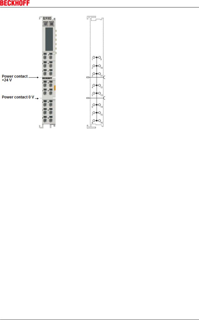
EL9183 [} 24] (Potential distribution terminal, 1 potential, 16 terminal points)
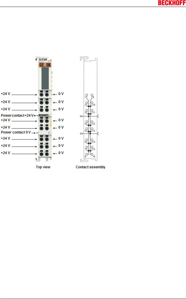
EL9184 [} 27] (Potential distribution terminals, 2 x 8 channels)
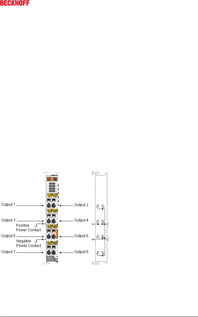
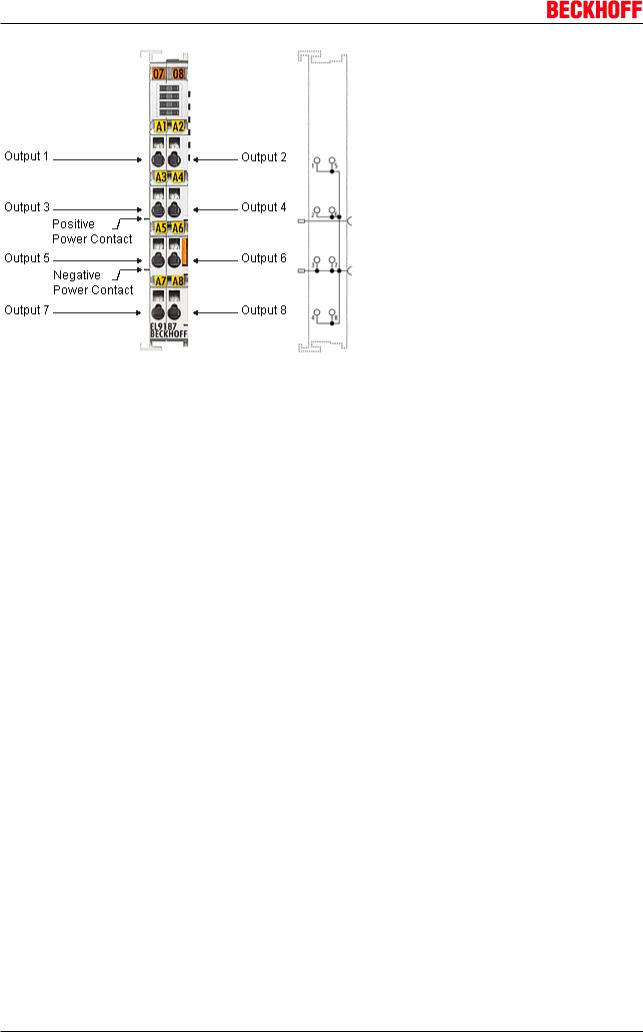
EL9186 [} 27], EL9187 [} 27] (Potential distribution terminals, 8 channels)
EL9188 [} 27], EL9189 [} 27] (Potential distribution terminals, 16 channels
EL9190 [} 17] (Feed terminal, up to 230 VAC)
EL9195 [} 33] (Shield terminal, up to 230 V AC/DC)
EL9200 [} 35] (Feed terminal, fused, 24 VDC)
EL9210 [} 35] (Feed terminal, fused, 24 VDC, with diagnosis)
EL9250 [} 39] (Feed terminal, fused, 230 VAC)
EL9260 [} 39] (Feed terminal, fused, 230 VAC, with diagnosis)
EL9290 [} 35] (Feed terminal, fused, up to 230 VAC)
EL9400 [} 42] (Power supply unit terminal for Ebus)
EL9410 [} 42] (Power supply unit terminal for Ebus with diagnosis
EL9540 [} 45] (Surge filter field supply)
EL9550 [} 45] (Surge filter system and field supply)
EL9570 [} 49] (Buffer capacitor terminal)
EL9xxx |
Version 3.1 |
5 |

Foreword
2 Foreword
2.1Notes on the documentation
This description is only intended for the use of trained specialists in control and automation engineering who are familiar with the applicable national standards.
It is essential that the following notes and explanations are followed when installing and commissioning these components.
The responsible staff must ensure that the application or use of the products described satisfy all the requirements for safety, including all the relevant laws, regulations, guidelines and standards.
Disclaimer
The documentation has been prepared with care. The products described are, however, constantly under development.
For that reason the documentation is not in every case checked for consistency with performance data, standards or other characteristics.
In the event that it contains technical or editorial errors, we retain the right to make alterations at any time and without warning.
No claims for the modification of products that have already been supplied may be made on the basis of the data, diagrams and descriptions in this documentation.
Trademarks
Beckhoff®, TwinCAT®, EtherCAT®, Safety over EtherCAT®, TwinSAFE®, XFC®and XTS® are registered trademarks of and licensed by Beckhoff Automation GmbH.
Other designations used in this publication may be trademarks whose use by third parties for their own purposes could violate the rights of the owners.
Patent Pending
The EtherCAT Technology is covered, including but not limited to the following patent applications and patents:
EP1590927, EP1789857, DE102004044764, DE102007017835
with corresponding applications or registrations in various other countries.
The TwinCAT Technology is covered, including but not limited to the following patent applications and patents:
EP0851348, US6167425 with corresponding applications or registrations in various other countries.
EtherCAT® is registered trademark and patented technology, licensed by Beckhoff Automation GmbH, Germany
Copyright
© Beckhoff Automation GmbH & Co. KG, Germany.
The reproduction, distribution and utilization of this document as well as the communication of its contents to others without express authorization are prohibited.
Offenders will be held liable for the payment of damages. All rights reserved in the event of the grant of a patent, utility model or design.
6 |
Version 3.1 |
EL9xxx |
Foreword
2.2Safety instructions
Safety regulations
Please note the following safety instructions and explanations!
Productspecific safety instructions can be found on following pages or in the areas mounting, wiring, commissioning etc.
Exclusion of liability
All the components are supplied in particular hardware and software configurations appropriate for the application. Modifications to hardware or software configurations other than those described in the documentation are not permitted, and nullify the liability of Beckhoff Automation GmbH & Co. KG.
Personnel qualification
This description is only intended for trained specialists in control, automation and drive engineering who are familiar with the applicable national standards.
Description of symbols
In this documentation the following symbols are used with an accompanying safety instruction or note. The safety instructions must be read carefully and followed without fail!
Serious risk of injury!
Failure to follow the safety instructions associated with this symbol directly endangers the life and health of persons.
DANGER
Risk of injury!
Failure to follow the safety instructions associated with this symbol endangers the life and health of persons.
WARNING
Personal injuries!
Failure to follow the safety instructions associated with this symbol can lead to injuries to persons.
CAUTION
Damage to the environment or devices
Failure to follow the instructions associated with this symbol can lead to damage to the en vironment or equipment.
Attention
Tip or pointer
This symbol indicates information that contributes to better understanding.
Note
EL9xxx |
Version 3.1 |
7 |

Foreword
2.3Documentation issue status
Version |
Comment |
3.1 |
Update chapter "Technical data" |
|
Addenda chapter "Installation instructions for enhanced mechanical load capacity" |
|
Update structure |
3.0 |
Update structure |
|
1st public issue in PDF format |
2.5 |
Update structure |
2.4 |
Technical data added |
2.3 |
Technical data added, EL9570 |
2.2 |
Update Technical data |
2.1 |
Update connection diagram EL9550 |
2.0 |
Addenda EL9540, EL9550 |
1.9 |
Technical data EL9070, EL9181, EL9182, EL9183 added |
1.8 |
Technical data EL9195 added |
1.7 |
Firmware compatibility note added |
1.6 |
Technical data added, EL9184, EL9188, EL9189 added |
1.5 |
Technical data added, EL9190, EL9200, EL9210, EL9250, EL9260, EL9290 added |
1.4 |
Technical data EL9150, EL9160 added |
1.3 |
Technical data EL9110, EL9410 added |
1.2 |
Technical data EL9100 changed |
1.1 |
Technical data EL9186, EL9187 added |
1.0 |
Technical data added |
0.1 |
first provisional documentation for EL9xxx |
8 |
Version 3.1 |
EL9xxx |

Foreword
2.4Version identification of EtherCAT devices
Designation
A Beckhoff EtherCAT device has a 14digit designation, made up of
• |
family key |
|
|
|
|
• |
type |
|
|
|
|
• |
version |
|
|
|
|
• |
revision |
|
|
|
|
|
|
|
|
|
|
Example |
Family |
Type |
Version |
Revision |
|
EL331400000016 |
EL terminal |
3314 (4channel |
0000 (basic type) |
0016 |
|
|
|
(12 mm, non |
thermocouple |
|
|
|
|
pluggable |
terminal) |
|
|
|
|
connection level) |
|
|
|
CU20080000000 |
CU device |
2008 (8port fast |
0000 (basic type) |
0000 |
|
0 |
|
|
ethernet switch) |
|
|
ES360200100017 |
ES terminal |
3602 (2channel |
0010 (high |
0017 |
|
|
|
(12 mm, pluggable |
voltage |
precision version) |
|
|
|
connection level) |
measurement) |
|
|
Notes
•the elements named above make up the technical designation
•The order designation, conversely, is made up of
family key (EL, EP, CU, ES, KL, CX, etc.)
type
version
•The revision shows the technical progress, such as the extension of features with regard to the EtherCAT communication, and is managed by Beckhoff.
In principle, a device with a higher revision can replace a device with a lower revision, unless specified otherwise, e.g. in the documentation.
Associated and synonymous with each revision there is usually a description (ESI, EtherCAT Slave Information) in the form of an XML file, which is available for download from the Beckhoff website. The revision has been applied to the IP20 terminals on the outside since 2014/01, see fig. 1.
•The type, version and revision are read as decimal numbers, even if they are technically saved in hexadecimal.
Identification number
Beckhoff EtherCAT devices from the different lines have different kinds of identification numbers:
Production lot/batch number/serial number/date code/D number
Serial number is the name generally given to the 8digit number that is printed on the device or attached to it on a sticker. This serial number indicates the asbuilt status on delivery and thus ambiguously marks a whole production lot.
Structure of the serial number: KK YY FF HH
KK week of production (CW, calendar week)
YY year of production
FF firmware version
HH hardware version
Example with ser. no.: 12063A02: 12 production week 12 06 production year 2006 3A firmware version 3A 02 hardware version 02
EL9xxx |
Version 3.1 |
9 |
Foreword
Exceptions can occur in the IP67 area , where the following syntax can be used (see respective device documentation):
Syntax: D ww yy x y z u
D prefix designation ww calendar week yy year
x firmware version of the bus PCB y hardware version of the bus PCB z firmware version of the I/O PCB u hardware version of the I/O PCB
Example: D.22081501 calendar week 22 of the year 2008 firmware version of bus PCB: 1 hardware version of bus PCB: 5 firmware version of I/O PCB: 0 (no firmware necessary for this PCB) hardware version of I/O PCB: 1
Unique serial number/ID
Beyond that there are some series in which each individual module has its own unique, sequential serial number.
See also the further documentation in the area
•IP67: EtherCAT Box
•Safety: TwinSafe
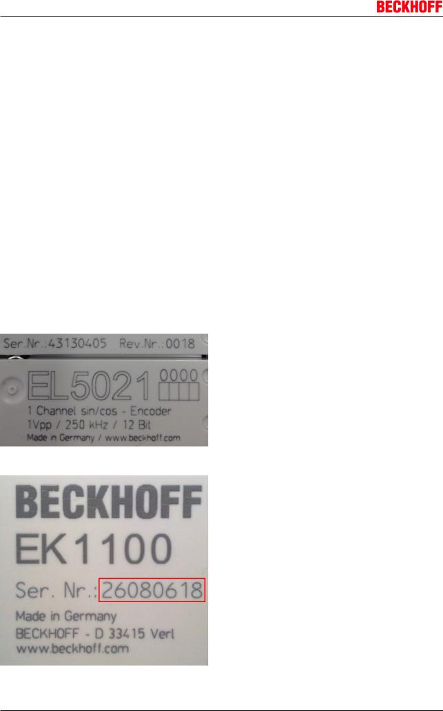
Examples of markings:
Fig. 1: EL5021 EL terminal, standard IP20 IO device with batch number and revision ID (since 2014/01)
Fig. 2: EK1100 EtherCAT coupler, standard IP20 IO device with batch number
10 |
Version 3.1 |
EL9xxx |

Foreword
Fig. 3: CU2016 switch with batch number
Fig. 4: EL32020020 with batch numbers 26131006 and unique Dnumber 204418
Fig. 5: EP125800001 IP67 EtherCAT Box with batch number 22090101 and serial number 158102
Fig. 6: EP19080002 IP76 EtherCAT Safety Box with batch number 071201FF and serial number 00346070
EL9xxx Version 3.1 11

Foreword
Fig. 7: EL2904 IP20 safety terminal with batch number/date code 50110302 and serial number 00331701
12 |
Version 3.1 |
EL9xxx |
Product overview
3 Product overview
3.1EL9011, EL9080
3.1.1EL9011, EL9080 Introduction and Technical Data
Fig. 8: EL9011
Each EtherCAT terminal block must be terminated at the right hand end with a EL9011 bus end cap due to mechanical and electrical protection.
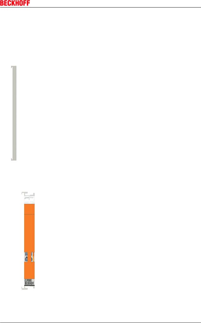
Fig. 9: EL9080
EL9xxx |
Version 3.1 |
13 |

Product overview
The EL9080 separation terminal interrupts the power contacts within a bus terminal block. The terminal enables operation with different voltages on the separated sides of the power contacts. But the KBus is looped through. The discontinuance of the Power Contacts is especially displayed by the orange front plate of the EL9080. The EL9080 separation terminal does not have any other function or connection facility.
Technical Data |
EL9011 |
EL9080 |
Electrical isolation |
yes |
|
Bit width in the process image |
0 |
|
Configuration |
no address or configuration settings |
|
Diagnosis |
|
|
PE contact |
no |
|
Electrical connection to |
no |
|
mounting rail |
|
|
Weight |
approx. 8 g |
approx. 40 g |
Permissible ambient |
25°C ... +60°C (extended temperature range) |
|
temperature |
0°C ... +55°C (according to cULus [} 74] for Canada and USA) |
|
|
0°C ... +55°C (according to ATEX, see special conditions) |
|
Permissible ambient |
40°C ... +85°C |
|
temperature range (during |
|
|
storage) |
|
|
Permissible relative humidity |
95%, no condensation |
|
Dimensions (W x H x D) |
approx. 7 mm x 100 mm x 34 mm |
approx.15 mm x 100 mm x 70 mm |
|
(width aligned: 5 mm) |
(width aligned: 12 mm) |
Mounting [} 60] |
aligned to the last terminal in the |
on 35 mm mounting rail conforms to |
|
terminal block |
EN 60715 |
Vibration/shock resistance |
conforms to EN 6006826/EN 60068227 |
|
EMC resistance burst/ESD |
conforms to EN 6100062/EN 6100064 |
|
Protect. class |
IP 20 |
|
Installation pos. |
variable |
|
Approval |
CE |
|
|
ATEX |
|
|
cULus [} 74] |
|
14 |
Version 3.1 |
EL9xxx |
Product overview
3.2EL9070
3.2.1EL9070 Introduction and Technical Data
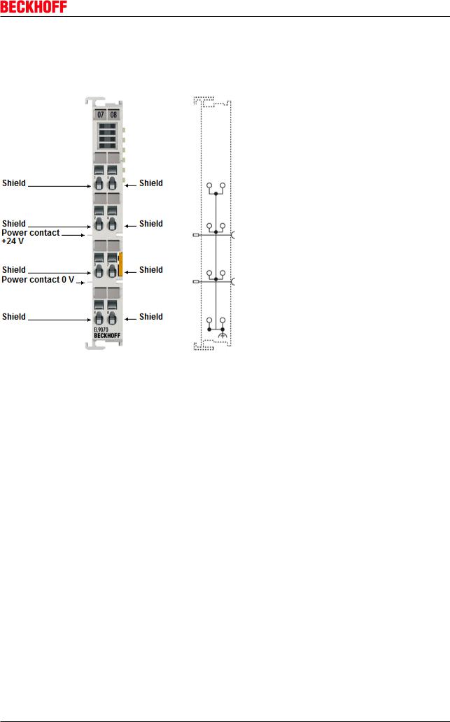
Fig. 10: EL9070
The EL9070 shield terminal provides eight terminal points with the potential of the mounting rail and enables the screening to be picked up without further modular terminal blocks or wiring. With its internal seamless copper surface, the EL9070 offers good screening between two EtherCAT Terminals.
EL9xxx |
Version 3.1 |
15 |

Product overview
Technical data
Technical Data |
EL9070 |
Technology |
shield terminal |
Current load |
≤ 10 A |
Power LED |
|
Error LED |
|
Current consumption Ebus |
|
Nominal voltage |
arbitrary up to 230 V AC |
Integrated finewire fuse |
|
Electrical isolation |
|
Diagnostics in the process image |
|
Reported to Ebus |
|
PE contact |
no |
Shield connection |
8 x |
Connection facility to additional power contact |
no |
Ebus looped through |
yes |
Bit width in the process image |
0 |
Electrical connection to mounting rail |
yes (dissipation of EMC interference via large copper |
|
surfaces on the mounting rail) |
Electrical connection to power contacts |
|
Configuration |
no address or configuration settings |
Dimensions (W x H x D) |
approx. 15 mm x 100 mm x 70 mm (width aligned: 12 |
|
mm) |
Weight |
approx. 50 g |
Permissible ambient temperature range (during |
0°C ... +55°C |
operation) |
|
Permissible ambient temperature range (during |
25°C ... +85°C |
storage) |
|
Permissible relative humidity |
95%, no condensation |
Mounting [} 60] |
on 35 mm mounting rail conforms to EN 60715 |
Vibration/shock resistance |
conforms to EN 6006826/EN 60068227 |
EMC resistance burst/ESD |
conforms to EN 6100062/EN 6100064 |
Protect. class |
IP 20 |
Installation pos. |
variable, see chapter "Mounting of Passive Terminals |
|
[} 70]" |
Approval |
CE |
Connection
Terminal point |
|
Meaning |
Indication |
No. |
|
1 8 |
1 8 |
Terminal points 1 8 are connected internally |
16 |
Version 3.1 |
EL9xxx |
Product overview
3.3EL9100, EL9110, EL9190
3.3.1EL9100, EL9110, EL9190 Introduction and Technical Data
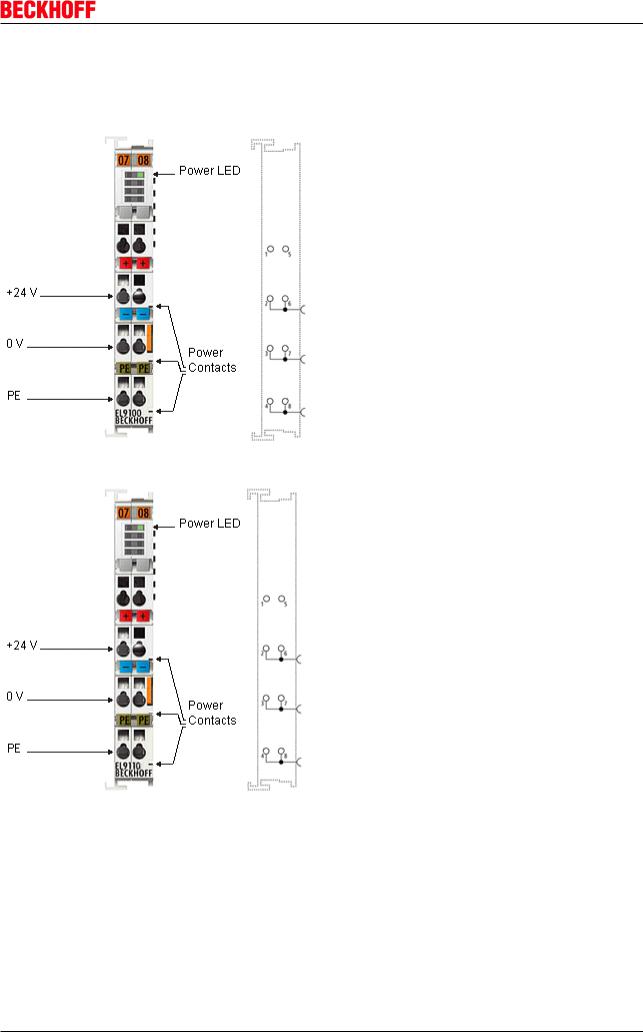
Fig. 11: EL9100
Fig. 12: EL9110
EL9xxx |
Version 3.1 |
17 |
Product overview
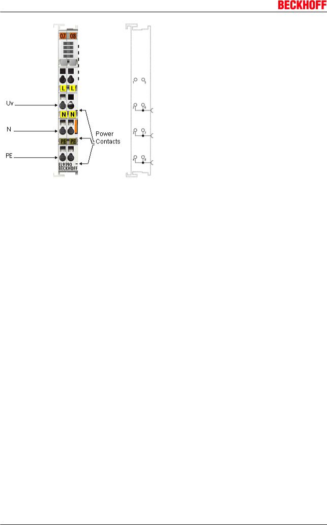
Fig. 13: EL9190
The EL9100 / EL9110 / EL9190 feed terminal can be positioned at any location between the input and output terminals for establishing a further potential group or for supplying the terminals following on the right in applications with high current load. The EBus is looped through. As opposed to the EL9100 / EL9190, the EL9110 has a diagnostic function which is displayed on the process image.
18 |
Version 3.1 |
EL9xxx |

|
|
|
|
Product overview |
Technical data |
|
|
|
|
|
|
|
|
|
Technical data |
EL9100 |
EL9110 |
EL9190 |
|
Nominal voltage |
24 VDC |
|
variable, up to 230 V AC/ |
|
|
|
|
DC |
|
Power contact current load |
max. 10 A |
|
|
|
Electrical isolation |
yes |
|
|
|
Current consumption from E |
|
typ. 90 mA |
|
|
Bus |
|
|
|
|
Bit width in the process image |
|
1 bit (diagnosis) |
|
|
Configuration |
no address or configuration settings |
|
|
|
Power LED |
yes |
yes |
no |
|
Diagnosis |
no |
yes, in process image |
no |
|
Electrical connection to |
no |
|
|
|
mounting rail |
|
|
|
|
PE contact |
yes |
|
|
|
Weight |
approx. 50 g |
|
|
|
Permissible ambient |
25°C ... +60°C (extended temperature range) |
0°C ... +55°C |
||
temperature range (during |
0°C ... +55°C (according to cULus [} 74] for |
|
|
|
operation) |
Canada and USA) |
|
|
|
|
0°C ... +55°C (according to ATEX [} 71], see |
|
|
|
|
special conditions [} 71]) |
|
|
|
Permissible ambient |
40°C ... +85°C |
|
25°C ... +85°C |
|
temperature range (during |
|
|
|
|
storage) |
|
|
|
|
Permissible relative humidity |
95%, no condensation |
|
|
|
Dimensions (W x H x D) |
approx. 15 mm x 100 mm x 70 mm (width aligned: 12 mm) |
|||
Mounting [} 60] |
on 35 mm mounting rail conforms to EN 60715 |
|
|
|
|
|
|
|
|
Vibration/shock resistance |
conforms to EN 6006826/EN 60068227, see |
|
conforms to EN |
|
|
Installation instructions [} 63] for enhanced |
|
6006826/EN |
|
|
mechanical load capacity |
|
|
60068227 |
EMC resistance burst/ESD |
conforms to EN 6100062/EN 6100064 |
|
|
|
Protect. class |
IP 20 |
|
|
|
Installation pos. |
variable, see chapter |
variable |
variable, see chapter |
|
|
"Mounting of Passive |
|
"Mounting of Passive |
|
|
Terminals [} 70]" |
|
Terminals [} 70]" |
|
Approval |
CE |
|
CE |
|
|
ATEX [} 71] |
|
cULus [} 74] |
|
|
cULus [} 74] |
|
|
|
|
|
|
|
|
Connection EL9100, EL9110, EL9190
Hazard to individuals and devices!
When designing a Bus Terminal block with different potentials on the power contacts (e.g. 230 V AC and 24 V DC), please note that it is mandatory to use potential separation termi
CAUTION nals (EL9080)!
Bring the bus system into a safe, powered down state before starting installation, disas sembly or wiring of the Bus Terminals!
EL9xxx |
Version 3.1 |
19 |

Product overview
Terminal point |
|
Description |
Indication |
No. |
|
|
1 |
not used |
+24 V* / 230 V AC** |
2 |
Supply input + 24 V [EL9100, EL9110] |
|
|
Supply input 230 V AC [EL9190: variable voltage, up to 230 V AC] |
|
|
connected internally with terminal 6 and positive [EL9100, EL9110] resp. 230 |
|
|
V AC [EL9190] power contact) |
0 V* / N** |
3 |
0 V for supply input [EL9100, EL9110] |
|
|
N for supply input [EL9190] |
|
|
connected internally with terminal 7 and negative [EL9100, EL9110] resp. |
|
|
neutral [EL9190] power contact) |
PE*** |
4 |
PE (connected internally with terminal 8 and PE power contact) |
|
5 |
not used |
+24 V* / 230 V AC** |
6 |
Supply input + 24 V [EL9100, EL9110] |
|
|
Supply input 230 V AC [EL9190: variable voltage, up to 230 V AC] |
|
|
connected internally with terminal 2 and positive [EL9100, EL9110] resp. 230 |
|
|
V AC [EL9190] power contact) |
0 V* / N** |
7 |
0 V for supply input [EL9100, EL9110] |
|
|
N for supply input [EL9190] |
|
|
connected internally with terminal 3 and negative [EL9100, EL9110] resp. |
|
|
neutral [EL9190] power contact) |
PE*** |
8 |
PE (connected internally with terminal 4 and PE power contact) |
**only EL9100, EL9110
***from hardware status 02
LEDs
LED |
Color |
Meaning |
|
Power LED** |
green |
off |
No input voltage at supply input |
|
|
on |
24 VDC at supply input |
** only EL9100, EL9110
Process data (only EL9110)
The EL 9110 has a bit width of 1 bit (diagnosis bit for the power contacts voltage, "PowerOK") and is displayed in the TwinCAT tree as follows:
Fig. 14: EL9110 in the TwinCAT tree
If there is no voltage impressed on the power contacts, the corresponding diagnosis bit 'PowerOK' has FALSE (0) status.
20 |
Version 3.1 |
EL9xxx |
Product overview
3.4EL9150, EL9160
3.4.1EL9150, EL9160 Introduction and Technical Data
Fig. 15: EL9150
The EL9150 feed terminal can be positioned at any location between the input and output terminals for establishing a further potential group or for supplying the terminals following on the right in applications with high current load. The EBus is looped through.
Fig. 16: EL9160
As opposed to the EL9150, the EL9160 has a diagnostic function which is displayed on the process image.
EL9xxx |
Version 3.1 |
21 |
Product overview
Technical data
Technical data |
EL9150 |
EL9160 |
Nominal voltage |
230 VAC (120 VAC ) |
|
Power contact current load |
max. 10 A |
|
Electrical isolation |
yes |
|
Current consumption from E |
|
typ. 90 mA |
Bus |
|
|
Bit width in the process image |
|
1 bit (diagnosis) |
Configuration |
no address or configuration settings |
|
Power LED |
yes |
|
Diagnosis |
no |
yes, in process image |
Electrical connection to |
no |
|
mounting rail |
|
|
PE contact |
no |
|
Weight |
approx. 50 g |
|
Permissible ambient |
0°C ... +55°C |
|
temperature range (during |
|
|
operation) |
|
|
Permissible ambient |
25°C ... +85°C |
|
temperature range (during |
|
|
storage) |
|
|
Permissible relative humidity |
95%, no condensation |
|
Dimensions (W x H x D) |
approx. 15 mm x 100 mm x 70 mm (width aligned: 12 mm) |
|
Mounting [} 60] |
on 35 mm mounting rail conforms to EN 60715 |
|
|
|
|
Vibration/shock resistance |
conforms to EN 6006826/EN 60068227 |
|
EMC resistance burst/ESD |
conforms to EN 6100062/EN 6100064 |
|
Protect. class |
IP 20 |
|
Installation pos. |
variable, see chapter "Mounting of |
variable |
|
Passive Terminals [} 70]" |
|
Approval |
CE |
|
|
ATEX [} 71] |
|
|
cULus [} 74] |
|
Connection EL9150 |
|
|
Hazard to individuals and devices!
When designing a Bus Terminal block with different potentials on the power contacts (e.g. 230 V AC and 24 V DC), please note that it is mandatory to use potential separation termi
CAUTION nals (EL9080)!
Bring the bus system into a safe, powered down state before starting installation, disas sembly or wiring of the Bus Terminals!
22 |
Version 3.1 |
EL9xxx |

|
|
|
|
Product overview |
|
|
|
|
|
Terminal point |
|
Description |
|
|
Indication |
No. |
|
|
|
|
1 |
not used |
|
|
230 VAC (120 VAC ) |
2 |
Supply input 230 VAC (120 VAC ), connected internally with terminal 6 and |
||
|
|
power contact) |
|
|
0 V |
3 |
0 V for supply input (connected internally with terminal 7 and power contact) |
||
PE |
4 |
PE (connected internally with terminal 8 and PE power contact) |
||
|
5 |
not used |
|
|
230 VAC (120 VAC ) |
6 |
Supply input 230 VAC (120 VAC ), (connected internally with terminal 2 and |
||
|
|
power contact) |
|
|
0 V |
7 |
0 V for supply input (connected internally with terminal 3 and power contact) |
||
PE |
8 |
PE (connected internally with terminal 4 and PE power contact) |
||
LEDs |
|
|
|
|
|
|
|
|
|
LED |
Color |
|
Meaning |
|
Power LED |
green |
|
off |
No input voltage at supply input |
|
|
|
on |
230 VAC (120 VAC ) at supply input |
Process data (only EL9160)
The EL9160 has a bit width of 1 bit (diagnosis bit for the power contacts voltage, "PowerOK") and is displayed in the TwinCAT tree as follows:
Fig. 17: EL9160 in the TwinCAT tree
If there is no voltage impressed on the power contacts, the corresponding diagnosis bit 'PowerOK' has FALSE (0) status.
EL9xxx |
Version 3.1 |
23 |
Product overview
3.5EL9181, EL9182, EL9183
3.5.1EL9181, EL9182, EL9183 Introduction and Technical Data
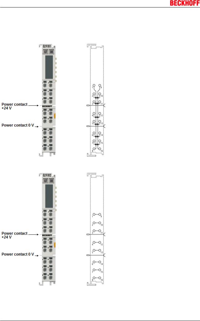
Fig. 18: EL9181
Fig. 19: EL9182
24 Version 3.1 EL9xxx
Product overview
Fig. 20: EL9183
The potential distribution terminals EL9181, EL9182 and EL9183 provide 16 terminal points for potential distribution and enable the voltage to be picked up without further terminal blocks or wiring. The power contacts are fed through to the next terminal without connecting to the terminal points.
The HD EtherCAT Terminals (High Density) with increased packing density feature 16 connection points in the housing of a 12 mm EtherCAT Terminal. The conductors can be connected without tools in the case of solid wires using a direct plugin technique
EL9xxx |
Version 3.1 |
25 |

Product overview
Technical data
Technical Data |
EL9181 |
EL9182 |
EL9183 |
Technology |
Potential distribution terminal |
|
|
Number of separate potentials |
2 |
8 |
1 |
Terminal points per potential |
8 |
2 |
16 |
Nominal voltage |
≤ 60 VDC |
|
|
Current load |
max. 10 A (per terminal point) |
|
|
Current consumption from E |
|
|
|
Bus |
|
|
|
Ebus looped through |
yes |
|
|
Power contacts looped |
yes (2 power contacts) |
|
|
through |
|
|
|
Diagnosis |
|
|
|
Message to EBus |
|
|
|
PE contact |
no |
|
|
Bit width in the process image |
0 |
|
|
Electrical connection to |
|
|
|
mounting rail |
|
|
|
Electrical connection to power |
|
|
|
contacts |
|
|
|
Electrical isolation |
|
|
|
Configuration |
no address or configuration settings |
|
|
Conductor types |
solid wire, stranded wire and ferrule |
|
|
Conductor connection |
solid wire conductors: direct plugin technique; stranded wire conductors and |
||
|
ferrules: spring actuation by screwdriver |
|
|
Rated crosssection |
solid wire: 0.08…1.5 mm²; stranded wire: 0.25…1.5 mm²; ferrule: 0.14…0.75 |
||
|
mm² |
|
|
Weight |
approx.. 60 g |
|
|
Permissible ambient |
0°C ... +55°C |
|
|
temperature range (during |
|
|
|
operation) |
|
|
|
Permissible ambient |
25°C ... +85°C |
|
|
temperature range (during |
|
|
|
storage) |
|
|
|
Permissible relative humidity |
95%, no condensation |
|
|
Dimensions (W x H x D) |
approx. 15 mm x 100 mm x 70 mm (width aligned: 12 mm) |
||
Mounting [} 60] |
on 35 mm mounting rail conforms to EN 60715 |
|
|
|
|
|
|
Vibration/shock resistance |
conforms to EN 6006826/EN 60068227 |
|
|
EMC resistance burst/ESD |
conforms to EN 6100062/EN 6100064 |
|
|
Protect. class |
IP 20 |
|
|
Installation pos. |
variable, see chapter "Mounting of Passive Terminals [} 70]" |
||
Approval |
CE |
|
|
Connection EL9181
Terminal point |
|
|
Meaning |
|
|
Indication |
No. |
|
|
||
1 |
8 |
1 |
8 |
Terminal points 1 |
8 are connected internally |
9 |
16 |
9 |
16 |
Terminal points 9 |
16 are connected internally |
26 |
Version 3.1 |
EL9xxx |
|
|
|
Product overview |
Connection EL9182 |
|
|
|
|
|
|
|
Terminal point |
|
|
Meaning |
Indication |
No. |
|
|
1, 9 |
1 |
+ 9 |
Terminal points 1 + 9 are connected internally |
2, 10 |
2 |
+ 10 |
Terminal points 2 +10 are connected internally |
3, 11 |
3 |
+ 11 |
Terminal points 3 + 11 are connected internally |
4, 12 |
4 |
+ 12 |
Terminal points 4 + 12 are connected internally |
5, 13 |
5 |
+ 13 |
Terminal points 5 + 13 are connected internally |
6, 14 |
6 |
+ 14 |
Terminal points 6 + 14 are connected internally |
7, 15 |
7 |
+ 15 |
Terminal points 7 + 15 are connected internally |
8, 16 |
8 |
+ 16 |
Terminal points 8 + 16 are connected internally |
Connection EL9183 |
|
|
|
|
|
|
|
Terminal point |
|
|
Meaning |
Indication |
No. |
|
|
1 16 |
1 |
16 |
Terminal points 1 16 are connected internally |
3.6EL9184, EL9186, EL9187, EL9188, EL9189
3.6.1EL9184, EL9186, EL9187, EL9188, EL9189 Introduction and Technical Data
EL9186, EL9187
Fig. 21: EL9186
EL9xxx |
Version 3.1 |
27 |
Product overview
Fig. 22: EL9187
The potential distribution terminals EL9186 and EL9187 provide 8 terminal points with a potential and enable the voltage to be picked up without further bus terminal blocks or wiring.
28 |
Version 3.1 |
EL9xxx |

Product overview
Technical Data
Technical Data |
EL9186 |
EL9187 |
Nominal voltage |
≤ 60 VDC |
|
Current load |
≤ 10 A |
|
Diagnosis |
|
|
Message to EBus |
|
|
PE contact |
no |
|
Shield connection |
|
|
Renewed power feed |
yes |
|
Outputs |
8 (connected with positive power |
8 x 0 V contact (connected with |
|
contact) |
negative power contact) |
Current consumption from E |
|
|
Bus |
|
|
Bit width in the process image |
0 |
|
Electrical connection to |
|
|
mounting rail |
|
|
Electrical isolation |
|
|
Side by side mounting on |
yes, left side without PE |
|
EtherCAT Terminals with |
|
|
power contact |
|
|
Side by side mounting on |
yes |
|
EtherCAT Terminals without |
|
|
power contact |
|
|
Configuration |
no address or configuration settings |
|
Weight |
approx.. 60 g |
|
Permissible ambient |
25°C ... +60°C (extended temperature range) |
|
temperature range (during |
0°C ... +55°C (according to cULus [} 74] for Canada and USA) |
|
operation) |
0°C ... +55°C (according to ATEX [} 71], see special conditions [} 71]) |
|
Permissible ambient |
40°C ... +85°C |
|
temperature range (during |
|
|
storage) |
|
|
Permissible relative humidity |
95%, no condensation |
|
Dimensions (W x H x D) |
approx. 15 mm x 100 mm x 70 mm (width aligned: 12 mm) |
|
Mounting [} 60] |
on 35 mm mounting rail conforms to EN 60715 |
|
|
|
|
Vibration/shock resistance |
conforms to EN 6006826/EN |
conforms to EN 6006826/ |
|
60068227 |
EN 60068227, see Installation |
|
|
instructions [} 63] for enhanced |
|
|
mechanical load capacity |
EMC resistance burst/ESD |
conforms to EN 6100062/EN 6100064 |
|
Protect. class |
IP 20 |
|
Installation pos. |
variable, see chapter "Mounting of Passive Terminals [} 70]" |
|
Approval |
CE |
|
|
ATEX [} 71] |
|
|
cULus [} 74] |
|
|
|
|
Connection EL9186
Terminal point |
|
Description |
|
Indication |
No. |
|
|
Output 1 8 |
1 8 |
Output 1 8 (internally connected with positive power |
|
|
|
contact) |
|
|
|
|
|
EL9xxx |
|
Version 3.1 |
29 |
Product overview
Connection EL9187
Terminal point |
|
Description |
Indication |
No. |
|
Output 1 8 |
1 8 |
Output 1 8 (internally connected with negative power |
|
|
contact) |
EL9184, EL9188, EL9189
Fig. 23: EL9184
30 |
Version 3.1 |
EL9xxx |
Loading...