


PROFIBUS
Bus Terminal Controller BC3100
Technical Hardware Documentation
Version 2.1 2006-11-06

Foreword
Contents
Foreword |
3 |
Notes on the documentation |
3 |
Safety Instructions |
4 |
Basic information |
5 |
The Beckhoff bus terminal system |
5 |
The interfaces |
7 |
The operating modes of the bus coupler |
9 |
Mechanical construction |
10 |
Electrical data |
12 |
The peripheral data in the process image |
13 |
Commissioning and diagnostics |
15 |
Run and reaction times |
17 |
Memory requirement |
18 |
PROFIBUS-DP basics |
19 |
Introducing the system |
19 |
PROFIBUS DP |
19 |
The transfer medium: plugs and cables |
24 |
Configuration of the masters |
26 |
PROFIBUS bus terminal controller BC3100 |
29 |
Parameterization |
29 |
Configuration |
32 |
Auto-configuration |
32 |
Diagnostics |
35 |
Data exchange |
37 |
Other DP services |
39 |
Acyclic DPV1 services |
39 |
Annex |
42 |
Example: a process image in the bus terminal controller |
42 |
Representation of analog signals in the process image |
46 |
Assignment of terminals in the integrated PLC |
47 |
Support and Service |
51 |
Beckhoff Headquarters |
51 |
2 |
BC3100 |

Foreword
Foreword
Notes on the documentation
This description is only intended for the use of trained specialists in control and automation engineering who are familiar with the applicable national standards. It is essential that the following notes and explanations are followed when installing and commissioning these components.
Liability Conditions
The responsible staff must ensure that the application or use of the products described satisfy all the requirements for safety, including all the relevant laws, regulations, guidelines and standards.
The documentation has been prepared with care. The products described are, however, constantly under development. For that reason the documentation is not in every case checked for consistency with performance data, standards or other characteristics. None of the statements of this manual represents a guarantee (Garantie) in the meaning of § 443 BGB of the German Civil Code or a statement about the contractually expected fitness for a particular purpose in the meaning of § 434 par. 1 sentence 1 BGB. In the event that it contains technical or editorial errors, we retain the right to make alterations at any time and without warning. No claims for the modification of products that have already been supplied may be made on the basis of the data, diagrams and descriptions in this documentation.
Delivery conditions
In addition, the general delivery conditions of the company Beckhoff Automation GmbH apply.
Copyright
© This documentation is copyrighted. Any reproduction or third party use of this publication, whether in whole or in part, without the written permission of Beckhoff Automation GmbH, is forbidden.
BC3100 |
3 |
Foreword
Safety Instructions
State at Delivery
All the components are supplied in particular hardware and software configurations appropriate for the application. Modifications to hardware or software configurations other than those described in the documentation are not permitted, and nullify the liability of Beckhoff Automation GmbH.
Description of safety symbols
The following safety symbols are used in this documentation. They are intended to alert the reader to the associated safety instructions..
This symbol is intended to highlight risks for the life or health of personnel.
 Danger
This symbol is intended to highlight risks for equipment, materials or the
environment.
 Attention
This symbol indicates information that contributes to better understanding.
i Note
4 |
BC3100 |

Basic information
Basic information
|
The Beckhoff bus terminal system |
|
The bus terminal system is the universal connecting link between a |
|
fieldbus system and the sensor/actor level. A unit consists of a bus terminal |
|
controller or a bus coupler, which is the interface to the fieldbus, and up to |
Up to 64 bus terminals |
64 electronic terminals, of which the last is an end terminal. Terminals, |
|
each with two I/O channels, are available for any form of technical signal |
each with 2 I/O channels |
and can be combined as desired. The various types of terminal are all |
for any form of signal |
constructed in the same way, so that the planning costs are kept extremely |
|
low. The height and depth of the construction are calculated for compact |
|
terminal cabinets. |
|
Fieldbus technology makes it possible to use compact control |
|
architectures. The I/O level does not need to be taken right up to the |
Decentralized wiring of the |
control unit. Sensors and actors can be connected decentrally with minimal |
I/O level |
lengths of cable. You can position the control unit at any convenient |
|
location in the installation. Using an industrial PC as control unit makes it |
IPC as control unit |
possible to implement the operating and monitoring element as part of the |
|
control hardware, so the control unit can be located on an operating desk, |
|
control point or similar. The bus terminals constitute the decentralized |
|
input/output level of the control unit in the switch cabinet and its |
|
subordinate terminal cabinets. As well as the sensor/actor level, the power |
|
unit of the equipment is also controlled via the bus system. The bus |
|
terminal replaces a conventional terminal as the cabling level in the switch |
|
cabinet; the switch cabinet can be made smaller. |
|
The Beckhoff bus terminal system combines the advantages of a bus |
|
system with the functionality of compact terminals. Bus terminals can be |
Bus terminal controllers for |
used on all current bus systems and serve to reduce the diversity of parts |
all current bus systems |
in the control unit, while behaving like the conventional standard units for |
|
the relevant bus system and supporting the entire range of functionality of |
|
the bus system. |
Standard C rail assembly |
The simple and compact assembly on a standard C rail, and the direct |
|
cabling of actors and sensors without cross connections between the |
|
terminals, serve to standardize the installation, as does the uniformly |
|
designed labeling. |
|
The small size and great flexibility of the bus terminal system mean that |
|
you can use it anywhere that you could use a terminal and use any type of |
|
connection – analog, digital, serial or direct sensors. |
Modularity |
The modular construction of the terminal row, using bus terminals with |
|
various functions, limits the number of unused channels to at most one per |
|
function. Two channels to a terminal is the optimum solution for the number |
|
of unused channels and the cost per channel. The possibility of using |
|
power input terminals to provide separate power supplies also helps to |
|
minimize the number of unused channels. |
Display of channel status |
The integrated light-emitting diodes close to the sensor/actor indicate the |
|
status of each channel. |
BC3100 |
5 |

Basic information
The K-bus |
The K-bus is the path taken by data within the terminal row. The bus |
|
terminal controller carries the K bus through all the terminals by means of |
End terminal |
six contacts on the side walls of the terminals, and the end terminal |
|
terminates the K bus. The user does not need to know anything about the |
|
function of the K bus or the internal operation of terminals and bus terminal |
|
controllers. There are numerous software tools available which provide for |
|
convenient planning, configuration and operation. |
Power input terminals |
Three power contacts pass the operating power to the following terminals. |
for |
You can use power input terminals to subdivide the terminal row as desired |
separately powered groups |
into groups, each with a separate power supply. These power input |
|
terminals are not taken into account for addressing the terminals, you can |
|
insert them at any position along the terminal row. |
|
You can install up to 64 terminals on a terminal row, including power input |
|
terminals and the end terminal. |
Profibus
The principle of the bus |
Bus terminal |
Powersupply |
Potential |
|
|
terminal |
controller |
|
|||
for the |
input |
Bus end |
|||
|
BC3100 |
||||
|
BC3100 |
terminal |
terminal |
||
|
|
|
K- bus |
|
x1 |
|
x10 |
BC3100 |
|
|
|
|
|
|
|
|
|
|
|
|
|
|
|
|
|
|
|
|
|
|
|
|
|
|
|
|
|
|
|
|
|
|
|
|
|
|
|
|
|
|
|
|
|
|
|
|
|
|
|
|
|
|
|
|
|
|
|
|
|
|
|
|
|
|
|
|
|
|
|
|
|
|
|
|
|
|
|
|
|
|
|
|
|
|
|
|
|
|
|
|
|
|
|
|
|
|
|
|
|
|
|
|
|
|
|
|
|
|
|
|
|
|
|
|
|
|
|
|
|
|
|
|
|
|
|
|
|
|
|
|
|
|
|
|
|
|
|
|
|
|
|
|
|
|
|
|
|
|
|
|
|
|
|
|
|
|
|
|
|
|
|
|
|
|
|
|
|
|
|
|
|
|
|
|
|
|
|
|
|
|
|
|
|
|
|
|
|
|
|
|
|
|
|
|
|
|
|
|
|
|
|
|
|
|
|
|
|
|
|
|
|
|
|
|
|
|
|
|
|
|
|
|
|
|
|
|
|
|
|
|
|
|
|
|
|
|
|
|
|
|
|
|
|
|
|
|
|
|
|
|
|
|
|
|
|
|
|
|
|
|
|
|
|
|
|
|
|
|
|
|
|
|
|
|
|
|
|
|
|
|
|
|
|
|
|
Power |
|
Potential |
|
|
|
|
|
|
|
||||
|
|
|
|
|
|
|
|
|
|
|
|
|
|
||||||
|
|
|
|
|
|
|
|
|
|
|
|
|
|
||||||
|
|
|
|
|
|
contacts |
|
isolation |
|
|
|
|
|
|
|
||||
Additional characteristics of the bus terminal controllers
Bus terminal controllers for various field bus systems
The bus terminal controllers (BC) differ from the bus couplers (BK) by virtue of the fact that a real time PLC task runs in addition to processing of the K-bus. Contrary to the bus couplers, by default the signals of the terminals are processed by the PLC task while inputs and outputs of the PLC task are then transmitted through the field bus. It is possible, however, to split up terminals so that some terminals are preprocessed by the PLC task, while others are forwarded directly via the field bus to the higher-level system.
Various bus terminal controllers can be used to link the electronic terminal strip with an integrated PLC task swiftly and easily to diverse field bus systems. Later conversion to a different field bus system is also possible. The bus terminal controller assumes all checking and control tasks that are needed for operation of the connected bus terminals. The bus terminals are operated and configured exclusively via the bus terminal controller. The field bus, the K-bus and the I/O level are electrically isolated.
6 |
BC3100 |
Basic information
|
|
The PLC task continues running as an autonomous system if the exchange |
|||||||
|
|
of data via the field bus should temporarily fail. |
|
||||||
|
|
The interfaces |
|
|
|
|
|||
|
|
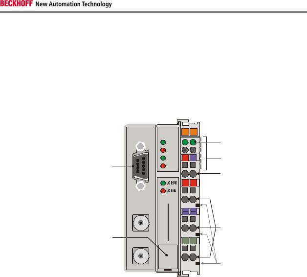
There are six ways of making a connection to a bus terminal controller. |
|||||||
|
|
These interfaces are designed as plug connections and spring terminals. |
|||||||
The |
Profibus |
controller |
|
|
|
|
X0 |
00 |
|
|
|
|
|
|
|
PROFIBUS |
01 |
2 |
Power LEDs |
BC3100 |
|
|
|
|
RUN |
|
|
||
|
|
|
|
|
|
Bus coupler / power contacts |
|||
|
|
|
|
|
|
BF |
|
|
|
|
|
|
|
|
|
|
|
|
|
|
|
Profibus |
|
|
|
DIA |
24V |
0V |
K-bus |
|
|
|
|
|
|
|
|
Power supply bus coupler |
|
|
|
|
|
|
|
|
|
|
|
|
|
|
|
|
|
BECKHOFF BC3100 |
+ + |
24 V DC / GND |
|
|
|
port |
x1 |
|
|
|
|||
|
|
|
|
|
|
|
|||
|
|
|
9 |
0 |
1 |
|
|
|
Input |
|
|
|
8 |
|
3 |
|
|
|
|
|
|
Configuration |
|
|
2 |
|
|
|
|
|
|
7 |
5 |
|
|
|
|
|
|
|
|
|
6 |
|
4 |
|
|
|
power contacts |
|
|
|
|
|
|
|
|
|
|
|
|
|
x10 |
|
PE |
PE |
|
||
|
|
|
|
|
|
|
|||
|
|
|
9 |
0 |
1 |
|
|
|
|
|
|
|
8 |
|
2 |
|
|
|
|
|
|
|
7 |
|
3 |
|
|
|
|
|
|
|
6 |
5 |
4 |
|
|
|
power contacts |
|
|
|
|
|
|
|
|
||
|
|
Power supply |
|
|
|
|
|
|
|
24 V DC on the topmost terminals
The bus terminal controllers need an operating power of 24 V DC which is connected via the topmost spring terminals, labeled "24 V“ and "0 V“. This power supply serves not only the electronic components of the bus terminal controller but (via the K bus) also the bus terminals. The power supply of the bus terminal controller circuitry and that of the K-bus (Terminal bus) are electrically isolated from the voltage of the field level.
|
Power supply to the power contacts |
Lower 3 terminal pairs for |
The six lower connections with spring terminals can be used to supply |
power input |
power to the peripherals. The spring terminals are connected in pairs to the |
|
power contacts. The power supply to the power contacts has no |
|
connection to the power supply of the bus couplers. The power input is |
maximum 24 V |
designed to permit voltages up to 24 V. The pair-wise arrangement and the |
|
electrical connection between the feed terminal contacts makes it possible |
|
to loop through the wires connecting to different terminal points. The load |
maximum 10 A |
on the power contact may not continuously exceed 10 A. The current |
|
capacity between two spring terminals is the same as the capacity of the |
|
connecting wires. |
Power contacts
On the right-hand side face of the BC3100 are three spring contacts which Spring contacts at the side are the power connections. The spring contacts are recessed in slots to prevent them from being touched. When a bus terminal is connected, the blade contacts on the left-hand side of the bus terminal are connected to the spring contacts. The slot and key guides at the top and bottom of the
BC3100 7

Basic information
|
|
|
bus terminal controller and bus terminals ensure reliable location of the |
|
|
|
power contacts. |
|
|
|
Fieldbus connection |
|
|
|
On the left-hand side there is a flat recessed area where you can plug in |
9-pin |
Sub-D |
female |
the typical Profibus male connectors. You will find a detailed description of |
connector |
|
the fieldbus interfaces in another part of this manual (In the chapter "The |
|
|
|
|
transfer medium: plugs and cables“). |
|
|
|
Configuration interface |
|
|
|
On the bottom side of the front area, the bus terminal controllers are |
Serial |
interface |
under the |
equipped with an RS 232 interface. The miniature connector can be |
front flap |
|
connected to a PC with a connecting cable and the KS2000 configuration |
|
|
|
|
software. The interface permits configuration of the analog channels. |
|
|
|
Depending on the scope of performance of the field bus, this functionality |
|
|
|
can also be realized with field bus-specific functions. |
|
|
|
The miniature connector also serves to connect to the TwinCAT PLC |
|
|
|
programming environment on a PC. It is used to load, start and stop the |
|
|
|
program, breakpoints are set and the program is run in the STEP mode |
|
|
|
etc. |
|
|
|
Depending on the scope of performance of the field bus and the availability |
|
|
|
of a corresponding TwinCAT field bus interface, this functionality can also |
|
|
|
be realized via the field bus, with the result that several bus terminal |
|
|
|
controllers that are physically connected to the same field bus can be |
|
|
|
operated without replugging an RS 232 connection. This feature is |
|
|
|
currently not yet supported by TwinCAT. |
|
|
|
K-bus contacts |
|
|
|
The connections between the BC3100 and the bus terminals are effected |
6 contacts at the side |
by gold contacts at the right-hand side of the bus terminal controller. When |
||
|
|
|
the bus terminals are plugged together, these gold contacts automatically |
|
|
|
complete the connection to the bus terminals. The K-bus is responsible for |
|
|
|
the power supply to the electronic components of the K-bus in the bus |
|
|
|
terminals, and for the exchange of data between the BC3100 and the bus |
|
|
|
terminals. Part of the data exchange takes place via a ring structure within |
|
|
|
the K-bus. Disengaging the K bus, for example by pulling on one the bus |
|
|
|
terminals, will break this circuit so that data can no longer be exchanged. |
|
|
|
However, there are mechanisms in place which enable the bus terminal |
|
|
|
controller to locate the interruption and report it. |
|
|
|
Supply isolation |
3 supply groups: |
|
The BC3100 operate with three independent supplies. The input power |
|
fieldbus |
|
supplies the electrically isolated K-bus circuitry in the bus terminal |
|
K-bus |
|
|
controller and the K-bus itself. The power supply is also used to generate |
peripheral level |
|
the operating power for the fieldbus. |
|
Note: All the bus terminals are electrically isolated from the K bus, so that the K-bus is completely electrically isolated.
8 |
BC3100 |
Basic information
Bus coupler |
Bus terminals |
Setting up the power levels
in the bus terminal system
 K-bus
K-bus
Field bus 

Periphery level
24 V DC
The operating modes of the bus coupler
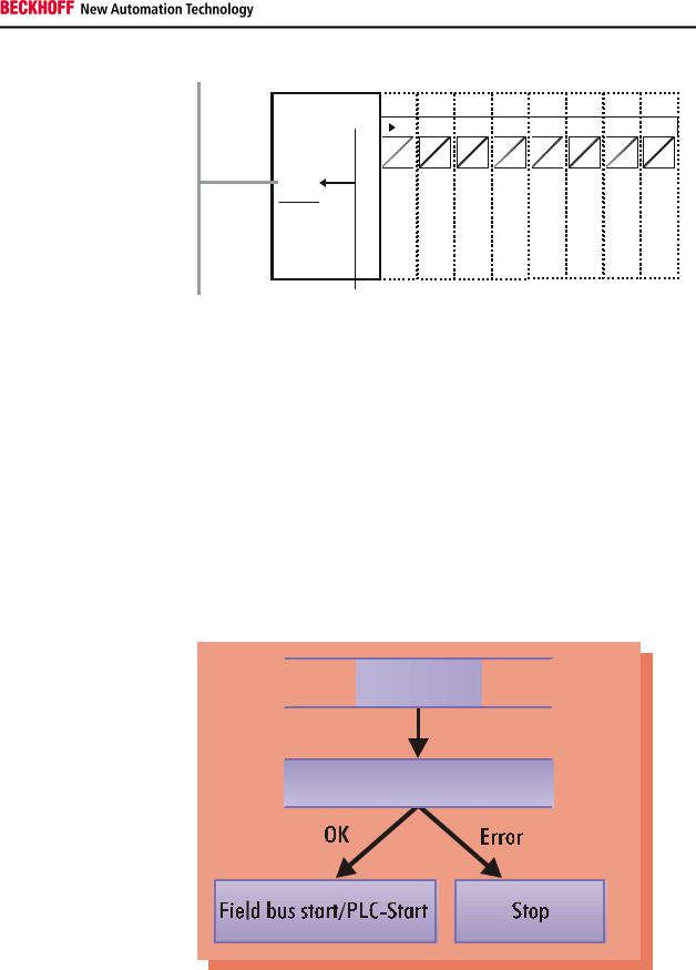
After power on, in a "self-test" the bus terminal controller checks all functions of its components and communication by the K-bus. The red I/O LED flashes during this phase. After successful completion of the self-test, the bus terminal controller begins to test the plugged in bus terminals (bus terminal test) and reads the configuration. An internal structure list is created on the basis of the bus terminals' configuration. The bus terminal controller assumes the "STOP" operating state in the event of an error. After error-free start up, the bus terminal controller assumes the "field bus start/PLC start" state. If a PLC program is stored in the flash memory, it is loaded and started regardless of whether the field bus is running. The inputs of the PLC task have been set to zero during start up.
Start-up behavior of the bus terminal controller


 Power on selftest


 Bus terminal test
  Structure list
Depending on the field bus functionality, the bus terminal controller reports a possible error via the field bus. The BC3100 generally has to be restarted after the error has been remedied.
BC3100 |
9 |
Basic information
Mechanical construction
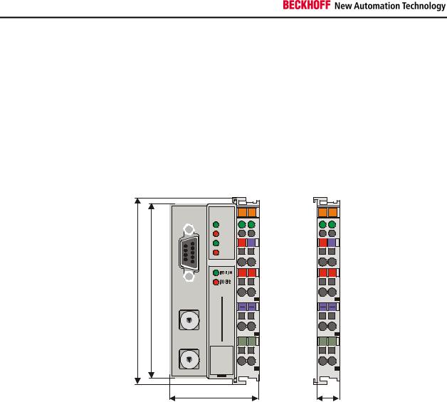
The Beckhoff bus terminal system is remarkable for its compact construction and high degree of modularity. When you design the installation you will need to plan for one bus terminal controller and some number of bus terminals. The dimensions of the bus terminal controller do not depend on the fieldbus system. If you use large plugs, for example like some of the bus plugs used for the Profibus, they may protrude above the overall height of the cabinet.
Dimensions of a bus terminal controller
|
|
|
|
PROFIBUS |
01 |
02 |
01 |
02 |
|
|
|
|
|
RUN |
|
|
|
|
|
|
|
|
|
BF |
|
|
|
|
|
|
|
|
|
DIA |
24V |
0V |
24V |
0V |
|
|
|
|
|
|
|
+ + |
+ + |
||
100 |
X1 |
|
|
|
|
|
|
||
9 |
0 |
1 |
|
|
|
|
|
|
|
8 |
|
2 |
|
|
|
|
|
|
|
|
|
|
|
|
|
|
|
||
7 |
|
3 |
|
|
|
|
|
|
|
|
|
|
|
|
|
|
|
||
6 |
5 |
4 |
|
|
|
|
|
|
|
94 |
|
BECKHOFF |
BC3100 |
|
|
|
|
||
|
|
PE |
PE |
PE |
PE |
||||
|
X10 |
|
|
||||||
|
|
|
|
|
|
|
|||
|
9 |
0 |
1 |
|
|
|
|
|
|
|
8 |
|
2 |
|
|
|
|
|
|
|
|
|
|
|
|
|
|
|
|
|
7 |
|
3 |
|
|
|
|
|
|
|
6 |
5 |
4 |
|
|
|
|
|
|
|
|
|
|
|
|
|
|
|
|
|
|
|
|
47 |
|
|
|
12 |
|
The overall width of the construction is the width of the BC3100, including the bus end terminal, plus the width of the installed bus terminals. The bus terminals are 12 mm or 24 mm wide, depending on their function. Depending on the gauge of cables used the overall height of 68 mm may be overstepped by about 5 mm to 10 mm by the cables at the front.
Assembly and connections It takes only a slight pressure to latch the bus terminal controller and the various bus terminals onto a supporting 35mm C rail and a locking mechanism then prevents the individual housings from being removed. You can remove them without effort if you first release the latching mechanism by pulling the orange tab. You should carry out work on the bus terminals and the bus terminal controller only while they are switched off: if you plug or unplug components while the power is on you may briefly provoke some undefined state (and, for instance, reset the bus coupler).
You can attach up to 64 bus terminals in series on the right-hand side of the BC3100. When you assemble the components, make sure that you mount the housings so that each slot comes together with the corresponding key. You cannot make any functional connections merely by pushing the housings together along the supporting track. When they are correctly mounted there should be no appreciable gap between the adjacent housings.
The right-hand side of a BC3100 is mechanically similar to a bus terminal. There are eight connections on the top which can be used to connect to thick-wire or thin-wire lines. The connection terminals are spring loaded.
10 |
BC3100 |
Basic information
|
You open a spring terminal by applying a slight pressure with a screwdriver |
|
or other pointed tool in the opening above the terminal and you can then |
|
insert the wire into the terminal without any obstruction. When you release |
|
the pressure the terminal will automatically close and hold the wire |
|
securely and permanently. |
|
The connection between bus terminal controller and bus terminals is |
|
automatically effected by latching the components together. The K bus is |
|
responsible for passing data and power to the electronic components of the |
|
bus terminals. In the case of digital bus terminals, the field logic receives |
|
power via the power contacts. Latching the components together has the |
|
effect that the series of power contacts constitutes a continuous power |
|
track. Please refer to the circuit diagrams of the bus terminals: some bus |
|
terminals do not loop these power contacts through, or not completely (e.g. |
|
analog bus terminals or 4-channel digital bus terminals). Each power input |
|
terminal interrupts the series of power contacts and constitutes the |
|
beginning of a new track. The bus terminal controller can also be used to |
|
supply power to the power contacts. |
Insulation test |
The power contact labeled "PE“ can be used as protective earth or ground. |
|
This contact stands proud for safety reasons and can carry short-circuit |
|
currents of up to 125A. Note that in the interests of electromagnetic |
|
compatibility the PE contacts are capacitively connected to the supporting |
|
track. This may lead to spurious results and even damage to the terminal |
|
when you test the insulation (e.g. insulation test for breakdown using a |
|
230V mains supply to the PE line). You should therefore disconnect the PE |
|
line on the bus coupler while you carry out insulation tests. You can |
|
disconnect other power supply points for the duration of the test by drawing |
|
the power supply terminals out from the remaining row of terminals by at |
|
least 10mm. If you do this, there will be no need to disconnect the PE |
|
connections. |
PE power contacts |
The protective earth power contact ("PE“) may not be used for any other |
|
connections. |
BC3100 |
11 |

Basic information
Electrical data
The electrical data specific to the field bus is listed in this chapter. The following table shows the data in an overview:
Technical data’s
Number of bus terminals
Digital peripheral signals
Analog peripheral signals
Maximum number of bytes
Programming possibility
Program size
Program memory
Data memory
Permament flags
Run time system
PLC cycle time
Programming languages
Field bus interface
Baud rates
Bus connection
Power supply
Input current
BC3100
64
256 inputs/outputs
128 inputs/outputs
512 bytes I and 512 bytes O
via programming interface (TwinCAT BC) or Profibus-DP (TwinCAT)
approximately 3000 plc statements
32 kbytes
32 kbytes
512 bytes
1 PLC task
approximately 3 ms for 1000 commands (including K-bus I/O cycle)
IL, LAD, CSF, SFC, ST
Profibus-DP
automatic baud rate detection up to 12 MBaud
1 x D-sub connector, 9-pole, with screen
24 V DC, (20...29 V DC)
70 mA + (total K-bus current/4
500 mA max.
Power-on current |
|
2.5 x continuous current |
|
|
|
Recommended fuse |
|
≤ 10 A, |
|
|
|
K-bus power supply up to |
|
1750 mA |
|
|
|
Power contact voltage |
|
24 V DC max. |
|
|
|
Power contact current load |
|
10 A max. |
|
|
|
Diaelectric strength |
|
500 Vrms (Power contact/supply voltage/field bus) |
|
|
|
Operating temperature |
|
0°C ... +55°C |
|
|
|
Storage temperature |
|
-25°C ... +85°C |
|
|
|
Relative humidity |
|
95%, no condensation |
|
|
|
Vibration/shock resistance |
|
in accordance withIEC 68-2-6 / IEC 68-2-27 |
|
|
|
EMC/emssion |
|
in accordance with EN 50082 (ESD, Burst) / EN 50081 |
|
|
|
Installed position |
|
any |
|
|
|
Degree of protection |
|
IP20 |
Current consumption on the For operation of the K-bus electronics, the bus terminals require energy K-Bus from the K-bus that is supplied by the bus terminal controller. Refer to the catalog or the corresponding data sheets of the bus terminals for details of the K-bus current consumption. In doing so, pay attention to the maximum output current of the bus terminal controller that is available for powering the bus terminals. Using a special power supply terminal (KL9400), power can be fed back into the K-bus at any chosen point. If you wish to use a
power supply terminal, please contact Beckhoff’s technical support.
12 |
BC3100 |

Basic information
Digital signals
(bit-oriented)
Analog signals (byte-oriented)
Special signals and interface
Word Alignment
BC3100
The peripheral data in the process image
After power on, the BC3100 determines the configuration of the plugged-in input/output terminals. The affiliations between the physical slots of the input/output channels and the addresses of the process image are defined automatically or by programming by the bus terminal controller depending on the settings via the configuration interface. If these affiliations are programmed, digital and analog signals can be distributed channel by channel in any order to the process image of the PLC task (global variables %I* (inputs) and %Q* (outputs)) or of the field bus (process data that is transferred through the field bus). The setting is defined manually with the configuration interface or, depending on the field bus functionality of the bus terminal controller, with the TwinCat System Manager at the variable level.
By default, automatic allocation is set for the bus terminal controllers. This is described below:
The BC3100 creates an internal allocation list in which the input/output channels have a specific position in the process image. Here, a distinction is made according to inputs and outputs and according to bit-oriented (digital) and byte-oriented (analog or complex) signal processing.
Two groups with only inputs and only outputs each are formed. The byteoriented channels are located in ascending order at the lowest address in one group. The bit-oriented channels are located after this block.
Digital signals are bit-oriented. This means that one bit of the process image is assigned to each digital channel. The bus terminal controller sets up a block of memory containing the current input bits and arranges to immediately write out the bits from a second block of memory which belongs to the output channels.
The precise assignment of the input and output channels to the process image of the control unit is explained in detail in the Appendix by means of an example.
The processing of analog signals is always byte-oriented and analog input and output values are stored in memory in a two-byte representation. The values are held as "SIGNED INTEGER“ or "twos-complement“. The digit "0“ represents the input/output value "0V“, "0mA“ or "4mA“. When you use the default settings, the maximum value of the input/output value is given by "7FFF“ hex. Negative input/output values, such as -10V, are represented as "8000“ hex and intermediate values are correspondingly proportional to one another. The full range of 15-bit resolution is not realized at every input/output level. If you have an actual resolution of 12 bits, the remaining three bits have no effect on output and are read as "0“ on input. Each channel also possesses a control and status byte in the lowest value byte. If the control/status byte is mapped in the control unit has to be configured in the master configuration software. An analog channel is represented by 2 bytes user data in the process image.
A bus terminal controller supports bus terminals with additional interfaces, such as RS232, RS485, incremental encoder, etc.. These signals can be regarded in the same way as the analog signals described above. A 16-bit data width may not be sufficient for all such special signals; the bus coupler can support any data width.
The analog or special signals are mapped with word alignment when the peripheral signals are allocated into the process image of the PLC task
13
Basic information
|
and, depending on the field bus, into the process image. |
Process image allocation |
By default, all terminals are allocated to the process image of the PLC task |
|
(beginning with the address %Q*0 or %I*0) but, via the configuration |
|
interface, the peripheral signals can also be allocated terminal by terminal |
|
to the field bus process image, with the result that they would be |
|
transmitted directly via the field bus without pre-processing by the PLC |
|
task. |
Default assignment of inputs and outputs to the process image
When the BC3100 is first switched on it determines the number of attached bus terminals and sets up a list of assignments. This list distinguishes between analog channels and digital channels and between input and output; which are grouped separately. The assignments begin immediately to the left of the BC3100. The software in the bus coupler creates the assignment list by collecting the entries for the individual channels one at a time, counting from left to right. These assignments distinguish four groups:
|
Function type of the channel |
Assignment level |
1. |
Analog outputs |
byte-wise assignment |
2. |
Digital outputs |
bit-wise assignment |
3. |
Analog inputs |
byte-wise assignment |
4 |
Digital inputs |
bit-wise assignment |
Output data in the BC3100
Input data in the BC3100
Analog inputs/outputs are representative of other complex multi-byte signal bus terminals (RS232, SSI sensor interface, ...)
Overview of the subdivision of the process image in the BC3100
O0
...
byte-oriented data
...
Ox
Ox+1
bit-oriented data
Ox+y
I0
...
byte-oriented data
...
Ix
Ix+1
...
bit-oriented data
...
Ix+y
Assignment of the process image of the PLC task to the field bus process image
Depending on the setting, the affiliations between the inputs and the outputs of the PLC task and the field bus process image are defined automatically by the BC3100 via the configuration interface or by programming. When assignments are programmed, inputs and outputs can be distributed bit by bit in any order to the field bus process image. This is set manually with the configuration interface or, depending on the field bus functionality of the bus terminal controller, with the TwinCAT System Manager at the variable level.
By default, automatic assignment is set for the bus terminal controllers. In this case, one coherent area each of the inputs or outputs of the PLC task can be mapped into the field bus process image. The initial offset and
14 |
BC3100 |

Basic information
|
length of the area to be mapped can be set by way of the configuration |
|
interface. As the terminal signals are placed into the process image of the |
|
PLC task as from address zero, the first meaningful offset as from when |
|
inputs and outputs of the PLC task are mapped into the field bus process |
|
image is the first free address where there are no longer any terminal |
|
signals. |
Data consistency |
Data which contains no contradictions is said to be consistent. The |
|
following consistency is required here: 1. The high byte and low byte of an |
|
analog value (word consistency), 2. The control/status byte and the |
|
corresponding parameter word for accessing the register. The interaction |
|
of the peripherals with the control unit means that data can initially be |
|
guaranteed consistent only within an individual byte: the bits which make |
|
up a byte are read in together, or written out together. Byte-wise |
|
consistency is quite adequate for processing digital signals but is not |
|
sufficient for transferring values longer than eight bits, such as analog |
|
values. The various bus systems guarantee consistency to the required |
|
length. It is important to use the appropriate procedure for importing this |
|
consistent data from the master bus system to the control unit. You will find |
|
a detailed description of the correct procedure in the User Guide of the |
|
appropriate bus system, in particular in the description of the standard |
|
master units that are installed. The chapters of this manual which deal with |
|
the fieldbus refer to the most common of these standard units. |
Processing complex signals All byte-oriented signal channels such as RS232, RS485 and incremental encoder, can use byte lengths greater than two. Apart from the actual difference in length, the procedure is always comparable with that for analog signals.
|
Commissioning and diagnostics |
|
After power on, the bus terminal controller immediately checks the |
|
connected configuration. Error-free start up is signalled by virtue of the fact |
|
that the red "I/O ERR" LED goes off. When it flashes, the "I/O ERR" LED |
|
indicates an error in the area of the terminals. The error code can be |
|
determined by the frequency and number of flashes. This enables swift |
|
troubleshooting. |
The diagnostic LEDs |
The bus terminal controller has two groups of LEDs to provide a status |
|
display. The top group consisting of four LEDs indicates the status of the |
|
respective field bus. The meanings of the "field bus" status LEDs are |
|
explained in the corresponding chapters of this manual. They correspond |
|
to the usual field bus displays. |
|
There are two further green LEDs on the top right hand side of the bus |
|
terminal controller to indicate the supply voltage. The left hand LED |
|
indicates the 24 V power supply of the bus terminal controller. The right |
|
hand LED signals the power supply of the Power contacts. |
BC3100 |
15 |
Basic information
Local errors
16
Two LEDs, the "I/O Leds" in the area under the above-mentioned field bus status LEDs, serve to indicate the operating states of the bus terminals and of the connection to these bus terminals. The green LED lights up whenever the signals to the terminals are being exchanged via the K-bus. After an error-free start up of the bus terminal controller, the K-bus exchange always takes place, even if the PLC program or the field bus is not running. The reaction (inputs or outputs change to zero or remain unchanged) to errors (field bus not running correctly or PLC task has assumed the STOP state) can be set via the configuration interface. To indicate errors, the red LED flashes at two different frequencies. Errors are encoded as follows in the flashing code:
Fast flashing |
|
Start of the error code |
|
|
|
First slow sequence |
|
Error code |
|
|
|
Second slow sequence |
|
Error argument |
Error code |
|
Error argument |
|
|
|
1 pulse |
|
0 |
|
|
1 |
|
|
2 |
2 pulses
0
n (n > 0)
Description
EEPROM checksum error
Inline code buffer overflow
Unknown data type
Programmed configuration Invalid table entry/
Bus terminal controller
Invalid table comparison (terminal n)
3 pulses |
|
0 |
|
Terminal bus command error |
|
|
|
|
|
4 pulses |
|
0 |
|
Terminal bus data error |
|
|
n |
|
Breakage after terminal n (0: BC3100) |
|
|
|
|
|
5 pulses |
|
n |
|
Terminal bus error during register |
|
|
|
|
communication with terminal n |
|
|
|
|
|
6 pulses |
|
0 |
|
Not enough DP-Cfg_Data received |
|
|
p(p>0) |
|
Invalid DP-Cfg_Data byte |
|
|
|
|
|
8 pulses |
|
0 |
|
Not enough DP-User_Prm_Data received |
|
|
p(p>0) |
|
Invalid DP-User_Prm_Data byte |
|
|
|
|
|
9 pulses |
|
0 |
|
Invalid checksum in the |
|
|
|
|
PLC program |
The number of pulses (n) indicates the position of the last bus terminal before the error. Passive bus terminals, for example an infeed terminal, are not counted.
In the case of some errors, the bus terminal controller does not end the flashing sequence when the error has been remedied. The bus terminal controller's operating state is still "Stop". The bus terminal controller can only be restarted by switching the supply voltage off and on or by means of a software reset.
It is only permitted to unplug bus terminals from the network and to plug them in again after switching off. The electronic circuitries of the bus terminals and of the bus terminal controller are largely protected against destruction, but malfunctions and damage cannot be ruled out if terminals are plugged together under a live voltage.
The occurrence of an error during ongoing operation does not immediately trigger output of the error code via the LEDs. The bus terminal controller must be prompted to diagnose the bus terminals. The diagnostic request is generated after power on.
BC3100
 Loading...