


Version: 3.5.1
Date: 2006-02-10
BK3xx0 - Bus Coupler for PROFIBUS DP

Contents
Contents
BK3xx0 - Bus Coupler for PROFIBUS DP
1. Foreword |
|
Notes on the Documentation |
3 |
Safety Instructions |
4 |
Documentation Issue Status |
5 |
2. Product Overview |
6 |
Technical Data |
6 |
Technical Data (Optical Fibres) |
9 |
System Overview |
10 |
PROFIBUS - Introduction |
12 |
PROFIBUS DP |
12 |
PROFIBUS DPV1 |
14 |
3. Mounting and Wiring |
15 |
Mechanical Installation |
15 |
Dimensions |
15 |
Assembly |
16 |
Wiring |
17 |
Potential groups, insulation testing and PE |
17 |
Power Supply and Potential Groups |
19 |
PROFIBUS Cabeling |
22 |
PROFIBUS Connection |
22 |
PROFIBUS Cabling |
24 |
4. Parameterisation and Commissioning |
26 |
Start-up behaviour of the Bus Coupler |
26 |
The Bus Coupler's UserPrmData |
27 |
Technical Data - Summary |
29 |
Configuration |
30 |
Configuration - CfgData |
30 |
Configuration of the Coupler Modules |
31 |
Configuration of Complex Modules |
32 |
Configuration of Digital Modules |
34 |
GSD Files |
35 |
Configuration Software KS2000 |
37 |
Configuration with TwinCAT |
38 |
Configuration with S7 |
41 |
Configuration: Siemens S7 Controller |
41 |
Configuration: Siemens S7 Controller BK3120 |
42 |
Fieldbus Components |
1 |

Contents
5. PROFIBUS DP Comunication |
47 |
Cyclic Data Exchange |
47 |
Process Data, Process Image |
47 |
K-Bus Cycle |
49 |
DPV1 - Acyclic Data Transfer |
53 |
DPV1 Interface |
53 |
Assignment of the DPV1 Slot Number |
54 |
DPV1 at the Coupler |
55 |
Module Assignment |
55 |
Firmware Information |
56 |
Terminal Composition |
57 |
K-Bus Status |
58 |
Cycle Time Measuring |
59 |
6. Diagnosis and Error Handling |
60 |
LEDs |
60 |
Overview |
60 |
DP Diagnostic |
65 |
DP Diagnostic Data (DiagData) |
65 |
Errors during DP Start-up |
68 |
Reaction to PROFIBUS Error |
70 |
K-Bus Diagnostic |
71 |
K-Bus Interruption |
71 |
Terminal Diagnostics |
72 |
7. Extended Functions |
73 |
2-byte PLC Interface |
73 |
Word Alignment |
74 |
Deactivating the CfgData Check |
75 |
Multi-Configuration Mode |
76 |
Changing the Size of the Process Data |
80 |
Implementation Levels of the Bus Coupler in |
|
Multi-Configuration Mode |
82 |
8. Appendix |
88 |
General Operating Conditions |
88 |
Approvals |
90 |
Bibliography |
91 |
List of Abbreviations |
92 |
Support and Service |
93 |
2 |
Fieldbus Components |

Notes on the Documentation
1. Foreword
Notes on the Documentation
This description is only intended for the use of trained specialists in control and automation engineering who are familiar with the applicable national standards. It is essential that the following notes and explanations are followed when installing and commissioning these components.
Liability Conditions
The responsible staff must ensure that the application or use of the products described satisfy all the requirements for safety, including all the relevant laws, regulations, guidelines and standards.
The documentation has been prepared with care. The products described are, however, constantly under development. For that reason the documentation is not in every case checked for consistency with performance data, standards or other characteristics. None of the statements of this manual represents a guarantee (Garantie) in the meaning of § 443 BGB of the German Civil Code or a statement about the contractually expected fitness for a particular purpose in the meaning of § 434 par. 1 sentence 1 BGB. In the event that it contains technical or editorial errors, we retain the right to make alterations at any time and without warning. No claims for the modification of products that have already been supplied may be made on the basis of the data, diagrams and descriptions in this documentation.
© This documentation is copyrighted. Any reproduction or third party use of this publication, whether in whole or in part, without the written permission of Beckhoff Automation GmbH, is forbidden.
Fieldbus Components |
3 |

Notes on the Documentation
Safety Instructions
Safety Rules
The responsible staff must ensure that the application or use of the products described satisfy all the requirements for safety, including all the relevant laws, regulations, guidelines and standards.
State at Delivery
All the components are supplied in particular hardware and software configurations appropriate for the application. Modifications to hardware or software configurations other than those described in the documentation are not permitted, and nullify the liability of Beckhoff Automation GmbH.
Personnel Qualification
This description is only intended for the use of trained specialists in control and automation engineering who are familiar with the applicable national standards.
Description of safety symbols
The following safety symbols are used in this operating manual. They are intended to alert the reader to the associated safety instructions.
This symbol is intended to highlight risks for the life or health of personnel.
Danger
This symbol is intended to highlight risks for equipment, materials or the environment.
Warning
This symbol indicates information that contributes to better understanding.
Note
4 |
Fieldbus Components |

Notes on the Documentation
Documentation Issue Status
Version |
Status |
|
|
3.5.1 |
Notes about UL certification added |
|
|
3.5 |
BK3150 with firmware version B0 added |
|
|
3.03 |
Corrections in the context of the translation into the english language |
|
|
3.02 |
GSD files updated for BK3110, BK3120, BK3520 |
|
|
3.01 |
Configuration examples for operation under Siemens S7 expanded. |
|
|
3.0 |
For BK3010 with firmware version B9 |
|
For BK3110 with firmware version B9 |
|
For BK3120 with firmware version B9 |
|
For BK3500 with firmware version B9 |
|
For BK3520 with firmware version B9 |
|
For LC3100 with firmware version B9 |
|
|
Fieldbus Components |
5 |
Notes on the Documentation
2. Product Overview
Technical Data
Technical data BK3000, BK3010, BK3100, BK3110, BK3120, LC3100
|
BK3000, |
|
BK3100, |
|
|
|
|
|
|
||
Type |
BK3010 |
|
BK3110 |
BK3120 |
LC3100 |
|
|
|
|
|
|
|
|
|
|
|
|
Number of Bus |
64 |
Terminals |
|
|
|
Digital peripheral |
512 inputs/outputs |
signals |
|
|
|
Analog peripheral |
128 inputs/outputs (BK3x00) |
signals |
|
64 (255 with K-Bus |
64 |
|
extension) |
|
|
max. 1020 |
256 inputs/outputs |
|
inputs/outputs |
|
|
max. 64 inputs/outputs |
|
|
- |
||
|
|
Configuration |
Via the KS2000 configuration software or the controller |
|
||
possibility |
|
|
|
|
|
|
|
|
|
Maximum number |
BK3000: 244 |
BK3100: |
128 bytes |
32 bytes |
of bytes |
bytes |
64 bytes (DP and |
|
|
(inputs and |
|
FMS operation) |
|
|
outputs) |
|
128 bytes (DP |
|
|
|
|
operation only) |
|
|
|
|
|
|
|
|
BK3010: 32 |
BK3110: 32 bytes |
|
|
|
bytes |
|
|
|
Baud rate |
up to max. |
up to max. 12 MBaud |
|
|
(automatic |
1.5 MBaud |
|
|
|
detection) |
|
|
|
|
|
|
|
|
|
Bus connection |
1 x D-sub plug, 9-pin with shielding |
|
spring-loaded terminals |
|
|
|
|
|
|
Power supply |
24 VDC (-15 % /+20 %) |
|
|
|
Input current |
70 mA + (total K-Bus current)/4, |
70 mA + (total K-Bus |
70 mA + (total K-Bus |
|
|
max. 500 mA (BK3x00) |
current)/4, max. 500 mA |
current)/4, max. 200 mA |
|
|
70 mA + (total K-Bus current)/4, |
|
|
|
|
max. 200 mA (BK3x10) |
|
|
|
Starting current |
2.5 x continuous current |
|
|
|
|
|
|
|
|
6 |
Fieldbus Components |
|
|
|
|
|
|
|
Notes on the Documentation |
|
|
|
|
|
|
|
|
|
|
|
|
|
|
|
|
|
|
|
|
|
BK3000, |
BK3100, |
|
|
|
|
|
|
Type |
BK3010 |
BK3110 |
|
BK3120 |
LC3100 |
|
|
|
|
|
|
|
|
|
|
|
|
|
|
|
|
|
|
||
|
|
|
|
|
|
|
||
K-Bus current up to |
1750 mA (BK3x00) |
|
1750 mA |
500 mA |
|
|||
|
|
500 mA (BK3x10) |
|
|
|
|
|
|
|
Power contact voltage |
maximum 24 VDC |
|
|
|
|
||
|
(Up) |
|
|
|
|
|
|
|
|
|
|
|
|
|
|
|
|
|
Power contact current |
maximum 10 A |
|
|
|
|
|
|
|
load (Up) |
|
|
|
|
|
|
|
|
|
|
|
|
|
|
|
|
|
Recommended fuse |
maximum 10 A |
|
|
|
|
|
|
|
(Up) |
|
|
|
|
|
|
|
|
|
|
|
|
|
|
||
|
Electrical isolation |
power contact / supply / fieldbus |
|
|
power supply / fieldbus |
|
||
|
|
|
|
|
|
|||
|
Dielectric strength |
500 Vrms (power contact / supply / fieldbus) |
500 Vrms (supply / |
|
||||
|
|
|
|
|
|
|
fieldbus) |
|
|
|
|
|
|
|
|
|
|
|
Weight |
approx. 170 g |
approx. 150 g |
|
approx. 170 g |
approx. 100 g |
|
|
|
|
|
|
|
|
|
|
|
|
Permissible ambient |
0 °C … +55 °C |
|
|
|
|
|
|
|
temperature |
|
|
|
|
|
|
|
|
(operation) |
|
|
|
|
|
|
|
|
|
|
|
|
|
|
|
|
|
Permissible ambient |
-25 °C … +85 °C |
|
|
|
|
|
|
|
temperature (storage) |
|
|
|
|
|
|
|
|
|
|
|
|
|
|
||
|
Permissible relative |
95 % (no condensation) |
|
|
|
|
||
|
humidity |
|
|
|
|
|
|
|
|
|
|
|
|||||
|
Vibration / shock |
according to EN 60068-2-6 / EN 60068-2-27, EN 60068-2-29 |
|
|||||
|
resistance |
|
|
|
|
|
|
|
|
|
|
|
|||||
|
EMC resistance Burst / |
according to EN 61000-6-2 (EN 50082) / EN 61000-6-4 (EN 50081) |
|
|||||
|
ESD |
|
|
|
|
|
|
|
|
|
|
|
|
|
|
|
|
|
Protection class |
IP 20 |
|
|
|
|
|
|
|
|
|
|
|
|
|
|
|
|
Installation position |
variable |
|
|
|
|
|
|
|
|
|
|
|
|
|
|
|
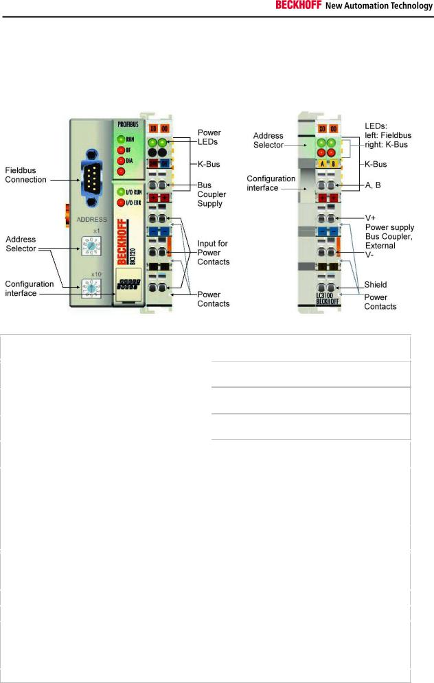
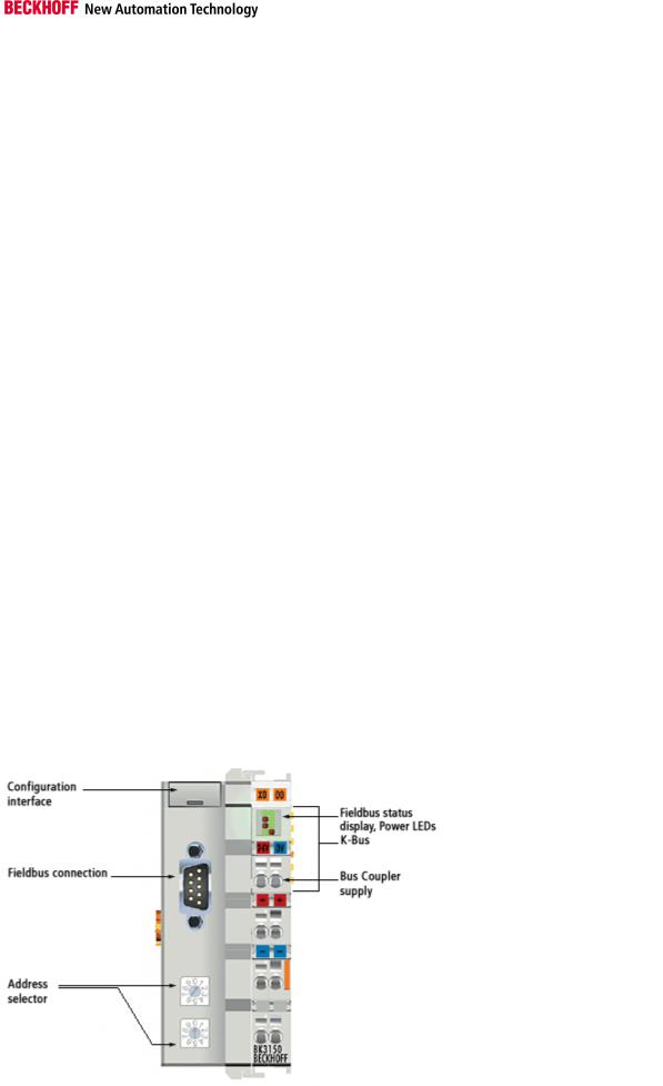
BK3150
Fieldbus Components |
7 |
Notes on the Documentation
Technical data BK3150
|
Type |
|
BK3150 |
|
|
|
|
|
|
|
|
|
|
|
Number of Bus Terminals |
|
64 (255 with K-Bus extension) |
|
|
|
|
|
|
|
|
|
|
|
Digital peripheral signals |
|
max. 1020 inputs/outputs |
|
|
|
|
|
|
|
|
|
|
|
Analog peripheral signals |
|
max. 64 inputs/outputs |
|
|
|
|
|
|
|
|
|
|
|
Configuration possibility |
|
Via the KS2000 configuration software or the controller |
|
|
|
|
|
|
|
|
|
|
|
Maximum number of bytes |
|
128 Byte (DP operation only) |
|
|
|
|
(inputs and outputs) |
|
|
|
|
|
|
|
|
|
|
|
|
|
Baud rate (automatic detection) |
|
up to max. 12 MBaud |
|
|
|
|
|
|
|
|
|
|
|
Bus connection |
|
1 x D-sub plug, 9-pin with shielding |
|
|
|
|
|
|
|
|
|
|
|
Power supply (Us) |
|
24 VDC (-15 % /+20 %) To meet the UL requirements use a 4 A fuse or |
|
|
|
|
|
|
a power supply that has to satisfy NEC class 2! |
|
|
|
|
|
|
|
|
|
|
|
Input current (Us) |
|
70 mA + (total K bus current)/4, max. 320 mA |
|
|
|
|
|
|
|
|
|
|
|
Starting current (Us) |
|
2,5 x continuous current |
|
|
|
|
|
|
|
|
|
|
|
Recommended fuse |
|
maximum 10 A |
|
|
|
|
|
|
|
|
|
|
|
K-Bus power supply up to |
|
1000 mA |
|
|
|
|
|
|
|
|
|
|
|
Power contact voltage |
|
maximum 24 VDC |
|
|
|
|
|
|
|
|
|
|
|
Power contact current load |
|
maximum 10 A |
|
|
|
|
|
|
|
|
|
|
|
Electrical isolation |
|
power contact / supply / fieldbus |
|
|
|
|
Dielectric strength |
|
500 Vrms (power contact / supply / fieldbus) |
|
|
|
|
Weight |
|
app. 100 g |
|
|
|
|
Permissible ambient temperature |
|
0 °C … +55 °C |
|
|
|
|
(operation) |
|
|
|
|
|
|
|
|
|
|
|
|
|
Permissible ambient temperature |
|
-25 °C … +85 °C |
|
|
|
|
(storage) |
|
|
|
|
|
|
|
|
|
|
|
|
|
Permissible relative humidity |
|
95 % (no condensation) |
|
|
|
|
|
|
|
|
|
|
|
Vibration / shock resistance |
|
according to EN 60068-2-6 / EN 60068-2-27, EN 60068-2-29 |
|
|
|
|
|
|
|
|
|
|
|
EMC resistance Burst / ESD |
|
according to EN 61000-6-2 / EN 61000-6-4 |
|
|
|
|
|
|
|
|
|
|
|
Protection class |
|
IP 20 |
|
|
|
|
|
|
|
|
|
|
|
Installation position |
|
variable |
|
|
|
|
|
|
|
|
|
|
8 |
Fieldbus Components |
Notes on the Documentation
Technical Data (Optical Fibres)
Technical data
Type |
BK3500 |
BK3520 |
|
|
|
|
|
Number of Bus Terminals |
64 |
64 (255 with K-Bus extension) |
|
|
|
|
|
Digital peripheral signals |
max. 512 inputs/outputs |
max. 1020 inputs/outputs |
|
|
|
|
|
Analog peripheral signals |
max. 64 inputs/outputs |
max. 64 inputs/outputs |
|
|
|
|
|
Configuration possibility |
Via the KS2000 configuration software or the controller |
|
|
|
|
|
|
Maximum number of bytes |
128 bytes |
128 bytes |
|
(inputs and outputs) |
|
|
|
|
|
|
|
Baud rates |
up to max. 1.5 Mbaud (manual |
up to max. 12 Mbaud (automatic |
|
|
setting) |
detection) |
|
|
|
|
|
Bus connection |
1 x optical fibre with 2 HP |
2 x optical fibres with 2 HP Simplex |
|
|
Simplex connectors |
connectors each |
|
|
|
|
|
Power supply |
24 VDC (-15 %/+20 %) |
|
|
|
|
|
|
Input current |
70 mA + (total K-Bus current)/4, 500 mA, 500 mA max. |
|
|
|
|
|
|
Starting current |
2.5 x continuous current |
|
|
|
|
|
|
Recommended fuse |
maximum 10 A |
|
|
|
|
|
|
K-Bus power supply up to |
1750 mA |
|
|
|
|
|
|
Power contact voltage |
maximum 24 VDC |
|
|
|
|
|
|
Power contact current load |
maximum 10 A |
|
|
|
|
|
|
Electrical isolation |
power contact / supply / fieldbus |
|
|
|
|
|
|
Dielectric strength |
500 Vrms (power contact / supply / fieldbus) |
|
|
|
|
|
|
Weight |
approx. 170 g |
approx. 170 g |
|
|
|
|
|
Permissible ambient temperature |
0 °C … +55 °C |
|
|
(operation) |
|
|
|
|
|
|
|
Permissible ambient temperature |
-25 °C … +85 °C |
|
|
(storage) |
|
|
|
|
|
|
|
Permissible relative humidity |
95 % (no condensation) |
|
|
|
|
|
|
Vibration / shock resistance |
according to EN 60068-2-6 / EN 60068-2-27, EN 60068-2-29 |
|
|
|
|
|
|
EMC resistance Burst / ESD |
according to EN 61000-6-2 (EN 50082) / EN 61000-6-4 (EN 50081) |
|
|
|
|
|
|
Protection class |
IP 20 |
|
|
|
|
|
|
Installation position |
variable |
|
|
|
|
|
|
Fieldbus Components |
|
9 |
|

Notes on the Documentation
The Beckhoff Bus Terminal System
Up to 64 Bus Terminals each having 2 I/O channels for each signal form
The Bus Terminal system is the universal interface between a fieldbus system and the sensor / actuator level. A unit consists of a Bus Coupler as the head station, and up to 64 electronic series terminals, the last one being an end terminal. For each technical signal form, terminals are available each having two I/O channels, and these can be mixed in any order. All the terminal types have the same mechanical construction, so that difficulties of planning and design are minimized. The height and depth match the dimensions of compact terminal boxes.
Decentralized wiring of each I/O level
Fieldbus technology allows more compact forms of controller to be used. The I/O level does not have to be brought to the controller. The sensors and actuators can be wired decentrally, using minimum cable lengths. The controller can be installed at any location within the plant.
Industrial PCs as controllers
The use of an Industrial PC as the controller means that the operating and observing element can be implemented in the controller’s hardware. The controller can therefore be located at an operating panel, in a control room, or at some similar place. The Bus Terminals form the decentralized input/output level of the controller in the control cabinet and the subsidiary terminal boxes. The power sector of the plant is also controlled over the bus system in addition to the sensor/actuator level. The Bus Terminal replaces the conventional series terminal as the wiring level in the control cabinet. The control cabinet can have smaller dimensions.
Bus Couplers for all usual bus systems
The Beckhoff Bus Terminal system unites the advantages of a bus system with the possibilities of the compact series terminal. Bus Terminals can be driven within all the usual bus systems, thus reducing the controller parts count. The Bus Terminals then behave like conventional connections for that bus system. All the performance features of the particular bus system are supported.
Assembly on standardized C mounting rails
The easy, space-saving, assembly on a standardized C-rail, and the direct wiring of actuators and sensors, without cross-connections between the terminals, standardizes the installation. The consistent labelling scheme also contributes.
The small physical size and the great flexibility of the Bus Terminal system allows it to be used wherever a series terminal is also used. Every type of connection, such as analog, digital, serial or the direct connection of sensors can be implemented.
Modularity
The modular assembly of the terminal strip with Bus Terminals of various functions limits the number of unused channels to a maximum of one per function. The presence of two channels in one terminal is the optimum compromise of unused channels and the cost of each channel. The possibility of electrical isolation through potential feed terminals also helps to keep the number of unused channels low.
Display of the channel state
The integrated LEDs show the state of the channel at a location close to the sensors and actuators.
10 |
Fieldbus Components |

Notes on the Documentation
K-Bus
The K-Bus is the data path within a terminal strip. The K-Bus is led through from the Bus Coupler through all the terminals via six contacts on the terminals’ side walls. The end terminal terminates the K-Bus. The user does not have to learn anything about the function of the K-Bus or about the internal workings of the terminals and the Bus Coupler. Many software tools that can be supplied make project planning, configuration and operation easy.
Potential feed terminals for isolated groups
The operating voltage is passed on to following terminals via three power contacts. You can divide the terminal strip into arbitrary isolated groups by means of potential feed terminals. The potential feed terminals play no part in the control of the terminals, and can be inserted at any locations within the terminal strip.
Up to 64 terminals can be used within one terminal strip. This count does include potential feed terminals, but not the end terminal.
Bus Couplers for various fieldbus systems
Various Bus Couplers can be used to couple the electronic terminal strip quickly and easily to different fieldbus systems. It is also possible to convert to another fieldbus system at a later time. The bus coupler performs all the monitoring and control tasks that are necessary for operation of the connected Bus Terminals. The operation and configuration of the Bus Terminals is carried out exclusively by the Bus Coupler. Nevertheless, the parameters that have been set are stored in each Bus Terminal, and are retained in the event of voltage drop-out. Fieldbus, K-Bus and I/O level are electrically isolated.
If the exchange of data over the fieldbus is prone to errors or fails for a period of time, register contents (such as counter states) are retained, digital outputs are cleared, and analog outputs take a value that can be configured for each output when commissioning. The default setting for analog outputs is 0 V or 0 mA. Digital outputs return in the inactive state. The timeout periods for the Bus Couplers correspond to the usual settings for the fieldbus system. When converting to a different bus system it is necessary to bear in mind the need to change the timeout periods if the bus cycle time is longer.
The interfaces
A Bus Coupler has six different methods of connection. These interfaces are designed as plug connectors and as spring-loaded terminals.
Fieldbus Components |
11 |

Notes on the Documentation
PROFIBUS - Introduction
PROFIBUS DP
In PROFIBUS DP systems, a master (PLC, PC etc.) usually communicates with a large number of slaves (I/Os, drives etc.). Only the master may here actively access the bus (send telegrams on its own initiative), while a DP slave only sends telegrams when it is requested to do so by a master.
DP StartUp
Before the master and slave can cyclically exchange data, the parameter and configuration data is transmitted from the master to the slaves during the DP StartUp phase. After the parameter and configuration data has been sent, the master interrogates the slave's diagnostic data until the slave indicates that it is ready for data exchange. Depending on the extent of the calculations that the slave must carry out after receiving the parameter and configuration data, it can take up to a few seconds before it is ready for data exchange. For this reason the slave possesses the following states:
Parameter data
The parameter data is sent from the master to the slave in the SetPrmLock request telegram. The SetPrmLock response telegram does not contain any data, and therefore consists of a single byte, the short acknowledgement. The parameter data consists of DP parameters (e.g. the setting of the DP watchdog or checking the IdentNumber (unique to each DP device)), of DPV1-/DPV2 parameters and of application-specific parameters that only have to be transmitted once during the StartUp. If an error is found in the parameter data, this is indicated in the diagnostic data, and the slave either remains in or enters the WAIT-PRM state.
Configuration data
The configuration data is sent from the master to the slave in the ChkCfg request telegram. The ChkCfg response telegram does not contain any data, and therefore consists of a single byte, the short acknowledgement. The configuration data describes the assignment of the DP modules to the cyclic I/O data that is to be exchanged between the master and slave via the Data_Exchange telegram in the cyclic data exchange phase. The sequence of the DP modules added to a slave in the DP configuration tool determines the sequence of the associated I/O data in the Data_Exchange telegram.
Diagnostic data
The diagnostic data is requested by the master using a SlaveDiag request telegram without any data. The slave replies with the diagnostic data in a SlaveDiag response telegram. The diagnostic data consists of the standard DP diagnostics (e.g. the state of the slave, the IdentNumber) and of application-specific diagnostic data.
Cyclic data exchange
The heart of the PROFIBUS DP protocol is cyclic data exchange, during which the master carries out an exchange of I/O data with every slave during a PROFIBUS DP cycle. This involves the master sending the outputs to each slave with a DataExchange request telegram, while the slave replies with the inputs in a DataExchange response telegram. This means that all the output and/or input data is transmitted in one telegram, in which the DP configuration (the sequence of DP modules) specifies the assignment of the output and/or input data to the slave's actual process data.
Diagnosis during cyclic data exchange
A slave can send a diagnostics signal to the master during cyclic data exchange. In this case, the slave sets a flag in the DataExchange response telegram, whereby the master recognises that there is new diagnostic data in the slave. It then fetches that data in the SlaveDiag telegram. This means that diagnostic data is not transmitted to the controller with the cyclic I/O data in real-time, but is always at least one DP cycle later.
12 |
Fieldbus Components |

Notes on the Documentation
Synchronisation with Sync and Freeze
The Sync and Freeze commands in the GlobalControl request telegram (broadcast telegram) allow the master to synchronise the activation of the outputs (Sync) or the reading of the inputs (Freeze) in a number of slaves. When the Sync command is used, the slaves are first switched into Sync mode (a process that is acknowledged in the diagnostic data). The I/O data is then exchanged sequentially with the slaves in the DataExchange telegram. Transmitting the Sync command in the GlobalControl telegram then has the effect of causing the slaves to generate the most recently received outputs. In Freeze operation a Freeze command is first sent in the GlobalControl telegram, in response to which all the slaves latch their inputs. These are then fetched sequentially by the master in the DataExchange telegram.
States in the master
The master distinguishes between the CLEAR state (all outputs are set to the Fail_Safe value) and the OPERATE state (all outputs have the process value). The Master is usually switched into the CLEAR mode when, for instance, the PLC enters STOP.
Class 1 and Class 2 DP Masters
The Class 1 master refers to the controller that carries out cyclic I/O data exchange with the slaves, while a Class 2 master is a B&B device that generally only has read access to the slaves' I/O data.
Fieldbus Components |
13 |

Notes on the Documentation
PROFIBUS DPV1
PROFIBUS DPV1 refers primarily to the acyclic read and write telegrams, with which data sets in the slave are acyclically accessed. A distinction between a Class 1 and a Class 2 master is also made for DPV1. The difference between acyclic Class 1 (C1) and Class 2 (C2) connections is that the acyclic C1 connection is established during the DP StartUp phase of cyclic DP operation. Once the slave has reached the WAIT-CFG state it is possible for acyclic DPV1-C1 read and write telegrams to be sent from the master to the slave, whereas the C2 connection is established separately, independently of the cyclic DP connection. This is usually carried out by a second (C2) master so that, for instance, a manufacturer-specific project configuration and diagnostic tool can access the slave's data.
When two masters are used, however, is must always be borne in mind that these share bus access (a token is exchanged), so that time relationships are less favourable than in the case of a single master system.
14 |
Fieldbus Components |

Notes on the Documentation
3. Mounting and Wiring
Mechanical Installation
Dimensions
The system of the Beckhoff Bus Terminals is characterized by low physical volume and high modularity. When planning a project it must be assumed that at least one Bus Coupler and a number of Bus Terminals will be used. The mechanical dimensions of the Bus Couplers are independent of the fieldbus system.
The total width in practical cases is composed of the width of the Bus Coupler with the KL9010 Bus End Terminal and the width of the Bus Terminals in use. Depending on function, the Bus Terminals are 12 or 24 mm wide. The front wiring increases the total height of 68mm by about 5 to 10 mm, depending on the wire thickness.
|
BK30x0, BK35x0, KL3110, |
|
|
Mechanical data |
BK3120 |
BK3150 |
LC3100 |
|
|
|
|
Material |
polycarbonate, polyamide (PA 6.6) |
|
|
|
|
|
|
Dimensions (W x H x D) |
50 mm x 100 mm x 68 mm |
44 mm x 100 mm x |
21 mm x 100 mm x |
|
|
68 mm |
68 mm |
|
|
|
|
Mounting |
on 35 mm C-rail conforming to EN50022 with lock |
|
|
|
|
|
|
Side by side mount. by |
double slot and key connection |
|
|
means of |
|
|
|
|
|
||
Marking |
standard terminal block marking and plain language side (8 mm x 47 mm, not |
||
|
BK3150) |
|
|
|
|
|
|
Fieldbus Components |
15 |

Notes on the Documentation
Installation
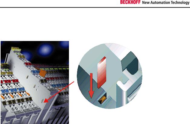
The Bus Coupler and all the Bus Terminals can be clipped, with a light press, onto a 35 mm mounting rail. A locking mechanism prevents the individual housings from being pulled off again. For removal from the mounting rail the orange colored tension strap releases the latching mechanism, allowing the housing to be pulled off the rail without any force.
Up to 64 Bus Terminals can be attached to the Bus Coupler on the right hand side. When plugging the components together, be sure to assemble the housings with groove and tongue against each other. A properly working connection can not be made by pushing the housings together on the mounting rail. When correctly assembled, no significant gap can be seen between the attached housings.
Insertion and removal of Bus Terminals is only permitted when switched off. The electronics
in the Bus Terminals and in the Bus Coupler are protected to a large measure against Warning damage, but incorrect function and damage cannot be ruled out if they are plugged in under
power.
The right hand part of the Bus Coupler can be compared to a Bus Terminal. Eight connections at the top enable the connection with solid or fine wires from 0.08 mm² to 2.5 mm². The connection is implemented with the aid of a spring device. The spring-loaded terminal is opened with a screwdriver or rod, by exerting gentle pressure in the opening above the terminal. The wire can be inserted into the terminal without any force. The terminal closes automatically when the pressure is released, holding the wire securely and permanently.
16 |
Fieldbus Components |

Notes on the Documentation
Wiring
Potential Groups, Insulation Testing and PE
Potential groups
The Beckhoff Bus Terminals stations usually have three different potential groups:
∙The fieldbus interface is electrically isolated (except for individual Low Cost couplers) and forms the first potential group
∙Bus Coupler / Bus Terminal Controller logic, K-Bus and terminal logic form a second galvanically separated potential group
∙The inputs and outputs are supplied via the power contacts and form further potential groups.
Groups of I/O terminals can be consolidated to further potential groups via potential supply terminals or separation terminals.
Insulation testing
The connection between the Bus Coupler / Bus Terminal Controller and the Bus Terminals is automatically realized by pushing the components together. The transfer of the data and the supply voltage for the intelligent electronics in the Bus Terminals is performed by the K-Bus. The supply of the field electronics is performed through the power contacts. Plugging together the power contacts creates a supply rail. Since some Bus Terminals (e.g. analog Bus Terminals or 4-channel digital Bus Terminals) are not looped through these power contacts (or not completely) the Bus Terminal contact assignments must be considered.
The potential feed terminals interrupt the power contacts, and represent the start of a new supply rail. The Bus Coupler / Bus Terminal Controller can also be made use of to feed the power contacts.
Fieldbus Components |
17 |
Notes on the Documentation
PE power contacts
The power contact labelled PE can be used as a protective earth. For safety reasons this contact mates first when plugging together, and can ground short-circuit currents of up to 125 A.
It should be noted that, for reasons of electromagnetic compatibility, the PE contacts are capacitively coupled to the mounting rail. This can both lead to misleading results and to damaging the terminal during insulation testing (e.g. breakdown of the insulation from a 230 V power consuming device to the PE conductor). The PE conductor to the Bus Coupler / Bus Terminal Controller must be disconnected for the insulation testing. In order to uncouple further feed locations for the purposes of testing, the feed terminals can be pulled at least 10 mm out from the connected group of other terminals. In that case, the PE conductors do not have to be disconnected.
The PE power contact must not be used for other potentials.
18 |
Fieldbus Components |
Notes on the Documentation
Power Supply
Bus Coupler / Bus Terminal Controller and Bus Terminal Supply (Us)
BKxx00, BKxx10, BKxx20 and LCxxxx
The Bus Coupler / Bus Terminal Controller require a 24 VDC supply for their operation.
The connection is made by means of the upper spring-loaded terminals labeled 24 V and 0 V. This supply voltage feeds the Bus Coupler / Bus Terminal Controller electronics and, over the K-Bus, the electronics of the Bus Terminals. It is electrically separated from the potential of the field level.
Fieldbus Components |
19 |

Notes on the Documentation
BKxx50 and BKxx51
The Bus Coupler / Bus Terminal Controller require a 24 VDC supply for their operation. To meet the UL requirements use 4 A fuse or class 2 power supply!
The connection is made by means of the upper spring-loaded terminals labeled Us and GNDs. This supply voltage feeds the Bus Coupler / Bus Terminal Controller electronics and, over the K-Bus, the electronics of the Bus Terminals. It is electrically separated from the potential of the field level.
UL requirements
 Danger
 Danger
For the compliance of the UL requirements Us should only be supplied
∙by a 24 VDC supply voltage, supplied by an isolating source and protected by means of a fuse (in accordance with UL248), rated maximum 4 Amp.
∙by a 24 VDC power source, that has to satisfy NEC class 2.
A NEC class 2 power supply shall not be connected in series or parallel with another (class 2) power source!
To meet the UL requirements, Us must not be connected to unlimited power sources!
Power contacts supply (Up)
The bottom six connections with spring-loaded terminals can be used to feed the supply for the peripherals. The spring-loaded terminals are joined in pairs to a power contact. The feed for the power contacts has no connection to the voltage supply for the Bus Coupler / Bus Terminal Controller.
The spring-loaded terminals are designed for wires with cross-sections between 0.08 mm² and 2.5 mm².
The assignment in pairs and the electrical connection between feed terminal contacts allows the connection wires to be looped through to various terminal points. The current drawn from the power contact must not exceed 10 A for long periods. The current carrying capacity between two spring-loaded terminals is identical to that of the connecting wires.
Power contacts
On the right hand face of the Bus Coupler / Bus Terminal Controller there are three spring contacts for the power contact connections. The spring contacts are hidden in slots so that they can not be accidentally touched. By attaching a Bus Terminal the blade contacts on the left hand side of the Bus Terminal are connected to the spring contacts. The tongue and groove guides on the top and bottom of the Bus Coupler / Bus Terminal Controller and of the Bus Terminals enables that the power contacts mate securely.
20 |
Fieldbus Components |

Notes on the Documentation
Configuration and Programming Interface
The Bus Coupler / Bus Terminal Controller have an RS232 interface at the bottom of the front face. The miniature connector can be joined to a PC and the KS2000 configuration software with the aid of a connecting cable. The interface permits the Bus Terminals to be configured, for example adjusting the amplification factors of the analog channels. The interface can also be used to change the assignments of the bus terminal data to the process image in the Bus Coupler. The functionality of the configuration interface can also be reached via the fieldbus using string communication facility.
Electrical isolation
The Bus Coupler / Bus Terminal Controller operate by means of three independent potential groups. The supply voltage feeds the K-Bus electronics and the K-Bus itself. The supply voltage is also used to generate the operating voltage for the fieldbus interface.
Remark: All the Bus Terminals are electrically isolated from the K-Bus. The K-Bus is thus electrically isolated from everything else.
Fieldbus Components |
21 |

Notes on the Documentation
PROFIBUS Cabeling
PROFIBUS Connection
M12 circular connector
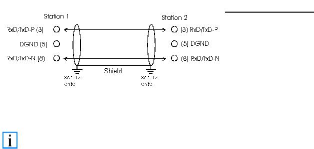
The M12 socket is inverse coded, and has five pins. Pin 1 is 5 VDC and 3 is GND for the active termination resistor. These must never be misused for other functions, as this can lead to destruction of the device. Pin 2 and pin 4 are the Profibus signals. These must never be swapped over, as this will prevent communication. Pin 5 is the shield, and this is capacitatively coupled to the Fieldbus Box chassis.
M12 socket pin assignment
Nine pole D-Sub
Pin 6 is 5 VDC und Pin 5 is GND for the active termination resistor. These must never be misused for other functions, as this can lead to destruction of the device. Pin 3 and pin 8 are the Profibus signals. These must never be swapped over, as this will prevent communication. Shield is connected to the D-Sub housing that is coupled with lowresistance to the mounting rail.
D-Sub socket pin assignment
22 |
Fieldbus Components |

|
|
|
Notes on the Documentation |
||
|
|
|
|
|
|
|
Profibus conductor colors |
|
|
|
|
|
|
|
|
|
|
|
Profibus conductors |
M12 |
|
D-Sub |
|
|
|
|
|
|
|
|
B red |
Pin 4 |
|
Pin 3 |
|
|
|
|
|
|
|
|
A green |
Pin 2 |
|
Pin 8 |
|
|
|
|
|
|
|
Connection of FieldbusBox modules
The connection of the Fieldbus Box modules is done direct or via a T-piece (or Y-piece).
The B318 series does have a male and female connector, that means no external T-piece is required. The supply voltage (+5VDC) for the termination resistor is only supplied via the female M12 connector. The termination resistor ZS1000-1610 is only available with male connector, therefore the incoming PROFIBUS line should end in a female connector.
Two T-pieces are available:
∙ZS1031-2600 with +5VDC on male and female connector for the termination resistor
∙ZS1031-2610 with +5VDC only on the female connector
Fieldbus Components |
23 |

Notes on the Documentation
PROFIBUS Cabling
Physical aspects of the data transmission are defined in the Profibus standard (see Profibus layer 1: Physical Layer).
The types of area where a fieldbus system can be used is largely determined by the choice of the transmission medium and the physical bus interface. In addition to the requirements for transmission security, the expense and work involved in acquiring and installing the bus cable is of crucial significance. The Profibus standard therefore allows for a variety of implementations of the transmission technology while retaining a uniform bus protocol.
Cable-based transmission
This version, which accords with the American EIA RS-485 standard, was specified as a basic version for applications in production engineering, building management and drive technology. A twisted copper cable with one pair of conductors is used. Depending on the intended application area (EMC aspects should be considered) the screening may be omitted.
Two types of conductor are available, with differing maximum conductor lengths (see the RS-485 table).
RS485 - Fundamental properties
RS-485 transmission according to the Profibus standard
Network topology |
Linear bus, active bus terminator at both ends, stubs are possible. |
|
|
Medium |
Screened twisted cable, screening may be omitted, depending upon the |
|
environmental conditions (EMC). |
|
|
Number of stations |
32 stations in each segment with no repeater. Can be extended to 127 stations |
|
with repeater |
|
|
Max. bus length without |
100 m at 12 MBit/s |
repeater |
200 m at 1500 KBit/s, up to 1.2 km at 93.75 KBit/s |
|
|
Max. bus length with |
Line amplifiers, or repeaters, can increase the bus length up to 10 km. The number |
repeater |
of repeaters possible is at least 3, and, depending on the manufacturer, may be up |
|
to 10. |
|
|
Transmission speed |
9.6 kBit/s; 19.2 kBit/s; 93.75 kBit/s; 187.5 kBit/s; 500 kBit/s; 1500 kBit/s; 12 MBit/s |
(adjustable in steps) |
|
|
|
Plug connector |
9-pin D-Sub connector for IP20 |
|
M12 round connector for IP65/67 |
|
|
Cabling for Profibus DP and Profibus FMS
Note the special requirements on the data cable for baud rates greater than 1.5 MBaud. The correct cable is a basic requirement for correct operation of the bus system. If a simple 1.5 Mbaud cable is used, reflections and excessive attenuation can lead to some surprising phenomena. It is possible, for instance, for a connected Profibus station not to achieve a connection, but for it to be included again when the neighboring station is disconnected. Or there may be transmission errors when a specific bit pattern is transmitted. The result of this can be that when the equipment is not operating, Profibus works without faults, but that there are apparently random bus errors after start-up. Reducing the baud rate (< 93,75 kBaud) corrects this faulty behavior.
If reducing the baud rate does not correct the error, then in many cases this can indicate a wiring fault. The two data lines maybe crossed over at one or more connectors, or the termination resistors may not be active, or they may be active at the wrong locations.
Installation is made a great deal more straightforward if pre-assembled cables from BECKHOFF are used! Wiring errors are avoided, and commissioning is more rapidly
Note completed. The BECKHOFF range includes fieldbus cables, power supply cables, sensor cables and accessories such as terminating resistors and T-pieces. Connectors and cables for field assembly are nevertheless also available.
24 |
Fieldbus Components |
Notes on the Documentation
|
In systems with more than two stations all devices are wired in parallel. It is essential that |
|
Note |
the bus cables are terminated with resistors at the conductor ends in order to avoid |
|
reflections and associated transmission problems. |
||
|
Distances
The bus cable is specified in EN 50170. This yields the following lengths for a bus segment.
Baud rate in kbits/sec |
9.6 |
19.2 |
93.75 |
187.5 |
500 |
1500 |
12000 |
|
|
|
|
|
|
|
|
Cable length in m |
1200 |
1200 |
1200 |
1000 |
400 |
200 |
100 |
|
|
|
|
|
|
|
|
Stubs up to 1500 kbaud <6.6 m; at 12 Mbaud stub segments should not be used.
Bus segments
A bus segment consists of at most 32 devices. 126 devices are permitted in a Profibus network. Repeaters are required to refresh the signal in order to achieve this number. Each repeater is counted as one device.
IP-Link is the subsidiary bus system for Fieldbus Boxes, whose topology is a ring structure. There is an IP master in the coupler modules (IP230x-Bxxx or IP230x-Cxxx) to which up to 120 extension modules (IExxxx) may be connected. The distance between two modules may not exceed 5 m. When planning and installing the modules, remember that because of the ring structure the IP-Link master must be connected again to the last module.
Installation guidelines
When assembling the modules and laying the cables, observe the technical guidelines provided by the Profibus User Organization (Profibus Nutzerorganisation e.V.) for Profibus DP/FMS (see www.profibus.com).
Checking the Profibus wiring
A Profibus cable (or a cable segment when using repeaters) can be checked with a few simple resistance measurements. The cable should meanwhile be removed from all stations:
1.Resistance between A and B at the start of the lead: approx. 110 Ohm
2.Resistance between A and B at the end of the lead: approx. 110 Ohm
3.Resistance between A at the start and A at the end of the lead: approx. 0 Ohm
4.Resistance between B at the start and B at the end of the lead: approx. 0 Ohm
5.Resistance between screen at the start and screen at the end of the lead: approx. 0 Ohm
If these measurements are successful, the cable is okay. If, in spite of this, bus malfunctions still occur, this is usually a result of EMC interference. Observe the installation notes from the Profibus User Organization (www.profibus.com).
Fieldbus Components |
25 |

Notes on the Documentation
4. Parameterisation and Commissioning
Start-up Behaviour of the Bus Coupler
Immediately after being switched on, the Bus Coupler checks, in the course of a self test, all the functions of its components and the communication on the K-Bus. The red I/O LED blinks while this is happening After completion of the self-test, the Bus Coupler starts to test the attached Bus Terminals (the Bus Terminal Test), and reads in the configuration. The Bus Terminal configuration is used to generate an internal structure list, which is not accessible from outside. In case of an error, the Bus Coupler enters the STOP state. Once the start-up has completed without error, the Bus Coupler enters the fieldbus start state.
The Bus Coupler can be made to enter the normal operating state by switching it on again once the fault has been rectified.
26 |
Fieldbus Components |
Notes on the Documentation
The Bus Coupler's UserPrmData
The following settings can be made in the Bus Coupler's UserPrmData. So that a more easily understood GSD file is obtained in 90% of applications, some of the settings are only contained in text form in the extended GSD file, and these are indicated in the last column by Extended. The standard settings are contained both in the standard and the extended GSD file.
Byte |
Bit |
Value |
Description |
GSD file |
0 |
7 |
0bin |
MSAC_C1 connection is not active (default) |
Standard |
|
|
1bin |
MSAC_C1 connection is active (see DPV1) |
|
1 |
0 |
0bin |
CfgData checking is active (default) |
Extended |
|
|
1bin |
CfgData checking deactivated (see Deactivating the CfgData checking) |
|
2 |
3 |
0bin |
Diagnostic data is transferred in a form compatible with the BK3100 |
Extended |
|
|
1bin |
Diagnostic data is transferred in a form compatible with DPV1 (default) |
|
3 |
3 |
0bin |
Multi-configuration mode is not active (default) |
Extended |
|
|
1bin |
Multi-configuration mode is active (see Multi-configuration mode) |
|
3 |
4 |
0bin |
K-Bus cycle counter is not active (default) |
Extended |
|
|
1bin |
K-Bus cycle counter is active (see K-Bus cycle) |
|
3 |
5 |
0bin |
Dummy output byte not active (default) |
Extended |
|
|
1bin |
Dummy output byte is active (see K-Bus cycle) |
|
3 |
6 |
0bin |
In multi-configuration mode, the coupler sets the Stat_Diag bit in the |
Extended |
|
|
|
diagnostic data if the configuration is not consistent, and does not yet enter |
|
|
|
|
data exchange (default). |
|
|
|
1bin |
In multi-configuration mode the coupler also enters data exchange even when |
|
|
|
|
the configuration is not consistent, although K-Bus cycles are not yet |
|
|
|
|
executed (see Multi-configuration mode) |
|
5 |
0 |
0bin |
2-byte PLC interface not activated (default) |
Extended |
|
|
1bin |
2-byte PLC interface is active (see 2-byte PLC interface) |
|
7 |
0 |
0bin |
Response to K-Bus error: manual K-Bus reset (default) (see K-Bus |
Standard |
|
|
|
interruption) |
|
|
|
1bin |
Response to K-Bus error: automatic K-Bus reset |
|
7 |
1 |
0bin |
Terminal diagnosis is not active (default) (see Terminal diagnosis) |
Standard |
|
|
1bin |
Terminal diagnosis is active |
|
7 |
4 |
0bin |
Diagnostic data for digital terminals included in process image (default) (see |
Standard |
|
|
|
Terminal diagnosis) |
|
|
|
1bin |
Diagnostic data of digital terminals not in the process image (default) |
|
9 |
2 |
0bin |
Analog modules are mapped in compact form (only showing the input and/or |
Extended |
|
|
|
output user data) (this is the default, only relevant when CfgData checking |
|
|
|
|
has been deactivated, otherwise the terminals are set by means of the |
|
|
|
|
CfgData) (see Deactivation of CfgData checking) |
|
|
|
1bin |
Analog modules are mapped in complex form (with control/status for register |
|
|
|
|
access and with the same data length in inputs and outputs) (only relevant |
|
|
|
|
when CfgData checking has been deactivated, otherwise the terminals are set |
|
|
|
|
by means of the CfgData) |
|
9 |
3 |
0bin |
Representation in INTEL format |
Standard |
|
|
1bin |
Representation in Motorola format (default) |
|
9 |
4 |
0bin |
K-Bus mode slow FreeRun (default) (see K-Bus cycle) |
Standard |
|
|
1bin |
K-Bus mode fast FreeRun |
|
Fieldbus Components |
27 |
 Loading...