


 Loading...
Hardware manual
CX51x0
EmbeddedPC
Version 1.0
Date 20150105

|
|
|
|
Table of contents |
Table of contents |
|
|||
1 |
Foreword .................................................................................................................................................... |
|
5 |
|
|
1.1 |
Notes on the documentation............................................................................................................. |
5 |
|
|
1.2 |
Safety instructions ............................................................................................................................ |
6 |
|
|
1.3 |
Documentation issue status.............................................................................................................. |
6 |
|
2 |
Product overview....................................................................................................................................... |
7 |
||
|
2.1 |
Intended use ..................................................................................................................................... |
7 |
|
|
2.2 |
System overview............................................................................................................................... |
8 |
|
|
2.3 |
CX5120 Technical data .................................................................................................................. |
10 |
|
|
2.4 |
CX5130 Technical data .................................................................................................................. |
11 |
|
|
2.5 |
CX5140 Technical data .................................................................................................................. |
12 |
|
|
2.6 |
Types .............................................................................................................................................. |
|
13 |
|
2.7 |
Battery compartment ...................................................................................................................... |
15 |
|
|
2.8 |
CFast slot........................................................................................................................................ |
17 |
|
|
2.9 |
CFast card ...................................................................................................................................... |
18 |
|
3 |
Seconds UPS ........................................................................................................................................... |
19 |
||
|
3.1 |
SUPS: capacitive onesecond UPS............................................................................................... |
19 |
|
|
3.2 |
Overview......................................................................................................................................... |
21 |
|
|
|
3.2.1 |
FUNCTION_BLOCK FB_S_UPS_CX51x0 ......................................................................... |
21 |
|
|
3.2.2 |
FUNCTION_BLOCK FB_NT_QuickShutdown.................................................................... |
24 |
|
3.3 |
Functions ........................................................................................................................................ |
25 |
|
|
|
3.3.1 |
FUNCTION F_GetVersionTcSUPS_CX51x0...................................................................... |
25 |
|
3.4 |
Data Types ..................................................................................................................................... |
26 |
|
|
|
3.4.1 |
TYPE E_S_UPS_Mode ...................................................................................................... |
26 |
|
|
3.4.2 |
TYPE E_S_UPS_State ....................................................................................................... |
26 |
4 |
Mounting and wiring ............................................................................................................................... |
27 |
||
|
4.1 |
Unpacking, installation and transport.............................................................................................. |
27 |
|
|
4.2 |
Dimensions ..................................................................................................................................... |
28 |
|
|
4.3 |
Installation on the mounting rail ...................................................................................................... |
30 |
|
|
4.4 |
Power supply .................................................................................................................................. |
32 |
|
|
4.5 |
Installation of passive terminals at the CX51x0 power supply unit ................................................. |
34 |
|
|
4.6 |
DVII port ........................................................................................................................................ |
35 |
|
|
4.7 |
USB connections ............................................................................................................................ |
36 |
|
|
4.8 |
LAN connections............................................................................................................................. |
37 |
|
|
4.9 |
RS232 connections (CX51x0N030)............................................................................................... |
39 |
|
|
4.10 |
RS422/RS485 connections (CX51x0N031)................................................................................... |
40 |
|
5 |
Commissioning/Configuration ............................................................................................................... |
42 |
||
|
5.1 |
BIOS setup ..................................................................................................................................... |
42 |
|
|
|
5.1.1 |
Main .................................................................................................................................... |
43 |
|
|
5.1.2 |
Advanced ............................................................................................................................ |
45 |
|
|
5.1.3 |
Chipset................................................................................................................................ |
63 |
|
|
5.1.4 |
Security ............................................................................................................................... |
68 |
|
|
5.1.5 |
Boot..................................................................................................................................... |
69 |
|
|
5.1.6 |
Save & Exit ......................................................................................................................... |
71 |
|
5.2 |
EtherCAT cable redundancy........................................................................................................... |
72 |
|
|
5.3 |
Switching on and off ....................................................................................................................... |
76 |
|
6 Error handling and diagnostics ............................................................................................................. |
77 |
|||
|
|
|
|
|
CX51x0 |
|
Version 1.0 |
3 |
|

Table of contents
|
6.1 |
Basic CPU module.......................................................................................................................... |
77 |
|
|
6.1.1 LEDs on the basic CPU module ......................................................................................... |
77 |
|
|
6.1.2 Kbus interface.................................................................................................................... |
78 |
|
|
6.1.3 LEDs of the Ebus power supply unit.................................................................................. |
81 |
|
6.2 |
Faults .............................................................................................................................................. |
82 |
7 |
Decommissioning.................................................................................................................................... |
83 |
|
|
7.1 |
Disassembly and disposal .............................................................................................................. |
83 |
8 |
Appendix .................................................................................................................................................. |
85 |
|
|
8.1 |
Accessories .................................................................................................................................... |
85 |
|
8.2 |
Certifications ................................................................................................................................... |
86 |
|
8.3 |
Support and Service ....................................................................................................................... |
87 |
4 |
Version 1.0 |
CX51x0 |

Foreword
1 Foreword
1.1Notes on the documentation
This description is only intended for the use of trained specialists in control and automation engineering who are familiar with the applicable national standards.
It is essential that the following notes and explanations are followed when installing and commissioning these components.
The responsible staff must ensure that the application or use of the products described satisfy all the requirements for safety, including all the relevant laws, regulations, guidelines and standards.
Disclaimer
The documentation has been prepared with care. The products described are, however, constantly under development.
For that reason the documentation is not in every case checked for consistency with performance data, standards or other characteristics.
In the event that it contains technical or editorial errors, we retain the right to make alterations at any time and without warning.
No claims for the modification of products that have already been supplied may be made on the basis of the data, diagrams and descriptions in this documentation.
Trademarks
Beckhoff®, TwinCAT®, EtherCAT®, Safety over EtherCAT®, TwinSAFE®, XFC®and XTS® are registered trademarks of and licensed by Beckhoff Automation GmbH.
Other designations used in this publication may be trademarks whose use by third parties for their own purposes could violate the rights of the owners.
Patent Pending
The EtherCAT Technology is covered, including but not limited to the following patent applications and patents:
EP1590927, EP1789857, DE102004044764, DE102007017835
with corresponding applications or registrations in various other countries.
The TwinCAT Technology is covered, including but not limited to the following patent applications and patents:
EP0851348, US6167425 with corresponding applications or registrations in various other countries.
EtherCAT® is registered trademark and patented technology, licensed by Beckhoff Automation GmbH, Germany
Copyright
© Beckhoff Automation GmbH & Co. KG, Germany.
The reproduction, distribution and utilization of this document as well as the communication of its contents to others without express authorization are prohibited.
Offenders will be held liable for the payment of damages. All rights reserved in the event of the grant of a patent, utility model or design.
CX51x0 |
Version 1.0 |
5 |
Foreword
1.2Safety instructions
Safety regulations
Please note the following safety instructions and explanations!
Productspecific safety instructions can be found on following pages or in the areas mounting, wiring, commissioning etc.
Exclusion of liability
All the components are supplied in particular hardware and software configurations appropriate for the application. Modifications to hardware or software configurations other than those described in the documentation are not permitted, and nullify the liability of Beckhoff Automation GmbH & Co. KG.
Personnel qualification
This description is only intended for trained specialists in control, automation and drive engineering who are familiar with the applicable national standards.
Description of symbols
In this documentation the following symbols are used with an accompanying safety instruction or note. The safety instructions must be read carefully and followed without fail!
Serious risk of injury!
Failure to follow the safety instructions associated with this symbol directly endangers the life and health of persons.
DANGER
Risk of injury!
Failure to follow the safety instructions associated with this symbol endangers the life and health of persons.
WARNING
Personal injuries!
Failure to follow the safety instructions associated with this symbol can lead to injuries to persons.
CAUTION
Damage to the environment or devices
Failure to follow the instructions associated with this symbol can lead to damage to the en vironment or equipment.
Attention
Tip or pointer
This symbol indicates information that contributes to better understanding.
Note
1.3Documentation issue status
Version |
|
Modifications |
|
1.0 |
|
First published |
|
0.1 |
|
Provisional version (original version) |
|
|
|
|
|
6 |
Version 1.0 |
CX51x0 |
|
Product overview
2 Product overview
2.1Intended use
The CX51x0 device series is a modular control system designed for tophat rail installation. The system is scalable, so that the required modules can be assembled and installed in the control cabinet or terminal box as required.
Only switch the PC off after closing the software
Before the Embedded PC is switched off, the software currently running on it should be stopped properly in order to avoid data loss on the hard disk. Please read the section on “Switching off [} 76]”.
Switch off all system components and uncouple the Industrial PC from the system if the PC is not used for control purposes, e.g. during a function test. To disconnect first pull the first terminal behind the power supply unit (optional), then pull the connectors of the fieldbus connections.
System components that have been switched off must be secured against being switched on again.
The Embedded PC’s power supply unit must be supplied with 24 VDC.
Damage to the environment or devices
Do not exchange any parts when under power! The exchange of controller parts when live can lead to shortcircuits or overvoltages. These can damage the controller itself and con
Attention nected peripherals (terminals, monitors, input devices, etc.).
When components are being fitted or removed, the supply voltage must be switched off.
Software knowledge
System malfunctions
Mandatory software knowledge! Every user must be familiar with any of the functions of the software installed on the PC that he can reach.
Attention
CX51x0 |
Version 1.0 |
7 |
Product overview
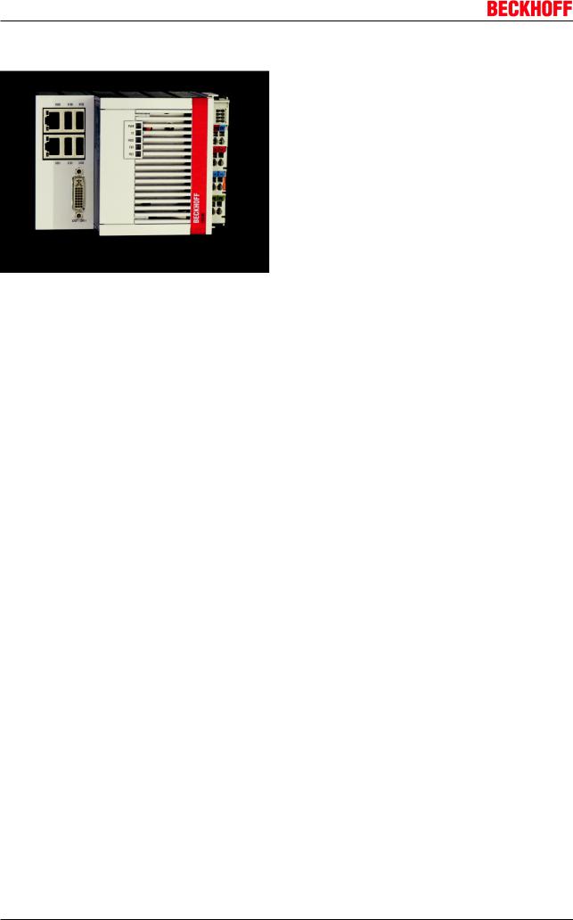
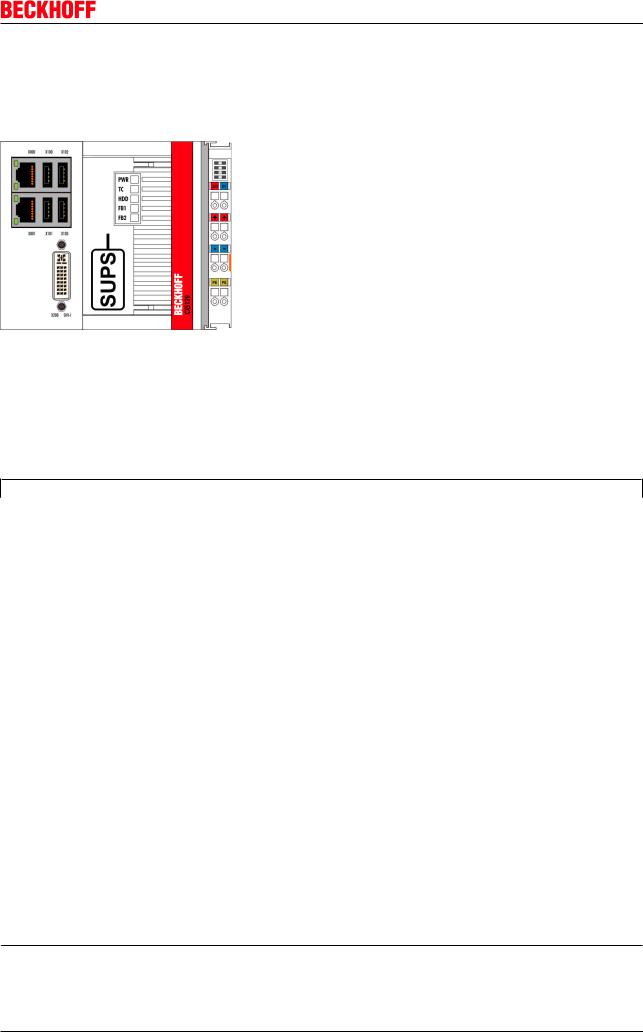
2.2System overview
The system
The CX51x0 series devices are DIN railmountable, fanless Embedded PCs with direct connection for Beckhoff Bus Terminals or EtherCAT Terminals. In contrast to the other CX device families, the CX51x0 series has a fixed, nonexpandable number of system interfaces. The housing design for this series is optimized for robustness and compactness. No modular expandability for the lefthand side is provided. Although EtherCAT integration offers a wide range of expansion capability. Further master/slave fieldbus connections (PROFIBUS, CANopen, DeviceNet) or communication interfaces (RS232, RS422/RS485) and all other signal types accessible via EtherCAT can be directly connected as EtherCAT Terminals. Two independent Gigabit Ethernet ports and four USB 2.0 interfaces are available. A Beckhoff Control Panel or a standard DVI monitor can be connected to the DVII interface. A serial port (RS232/RS422/RS485) or a fieldbus connection with master or slave function can be added as an optional interface as required. An interchangeable CFast card located behind a flap that is accessible from outside is used as boot and storage medium. The builtin capacitive 1second UPS ensures secure backup of persistent application data on the CFast card. The date and time are buffered via a replaceable battery. The operating system is Microsoft Windows Embedded Standard 7 Professional. The TwinCAT automation software transforms a CX51x0system into powerful PLC and Motion Control system that can be operated with or without visualization.
EtherCAT as a fast I/O system
Like all Embedded PCs from the CX series (except CX100x), the CX51x0 was developed for optimum interaction with EtherCAT. The primary EtherCAT connection is generally established via terminals. This is where EBus Terminals are attached. In addition, one of the Ethernet interfaces of the CPU module (X001) is parameterized for EtherCAT operation, and external EtherCAT components can be connected. To achieve line redundancy, both interfaces can be interconnected as a ring.
EtherCAT offers several options for connecting conventional fieldbus systems to the CX51x0. EtherCAT devices in terminal form provide several fieldbus masters and slaves, for example the PROFIBUS master as EtherCAT Terminal EL6731. In practice, this means that the PROFIBUS master can be positioned exactly where it is required within a machine.
PLC, Motion Control, interpolation and visualization
As a DIN rail IPC and in conjunction with the TwinCAT software from Beckhoff, the CX51x0 offers the same functionality as large Industrial PCs. In terms of PLC, up to four virtual IEC 61131 CPUs can be programmed with up to four tasks each, with a minimum cycle time of 50 μs. All IEC 611313 languages can be used.
Moreover, all TwinCAT functionalities are available for Motion Control applications:
in theory, up to 256 axes can be controlled and in addition to simple pointtopoint movements, more complex multiaxis functions such as “electronic gearbox”, “cam plates” and “flying saw” can be implemented.
8 |
Version 1.0 |
CX51x0 |

Product overview
In addition to realtime execution of control tasks, the TwinCAT realtime kernel ensures that enough time remains for the user interface (HMI), to communicate with the realtime components via software interfaces such as ADS or OPC.
For CX51x0 the familiar basic principle applies: it is a programming tool for all controllers.
The complete programming of PLC, Motion Control and visualization is transferable to all PC controls from Beckhoff, which is reassuring in cases where it becomes apparent during a project that more processing power is required after all. In this case a system with higher performance can be used.
Optional interfaces:
The optional interfaces can be used to connect singlechannel fieldbus interfaces. Operation is limited to one interface at a time. If several fieldbus interfaces are required, they can be added as Ebus terminals (EL67xx). The following fieldbus interfaces are available:
•CX51x0N030 = RS232, DSub connector
•CX51x0N031 = RS422/RS485, DSub socket
•CX51x0M310 = PROFIBUS master, DSub socket, 9pin
•CX51x0B310 = PROFIBUS slave, DSub socket, 9pin
•CX51x0M510 = CANopen master, DSub connector, 9pin
•CX51x0B510 = CANopen slave, DSub connector, 9pin
•CX51x0M930 = PROFINET RT, controller, Ethernet (2 x RJ45 switch)
•CX51x0B930 = PROFINET RT, device, Ethernet (2 x RJ45 switch)
•CX51x0B951 = Ethernet/IP slave, Ethernet (2 x RJ45 switch)
•CX51x0B100 = EtherCAT slave, EtherCAT IN and OUT (2 x RJ 45)
•CX5130N020 = second DVID interface
•CX5140N020 = second DVID interface
The software
In combination with the TwinCAT automation software, the CX51x0 Embedded PC becomes a powerful IEC 611313 PLC with up to four user tasks. Additionally, Motion Control tasks can also be executed. Depending on the required cycle time, several servo axes can be controlled. Even special functions such as “flying saw”, “electronic gearbox” and cam plate can be realized.
The CX51x0 system is programmed in the same way as other bus controllers:
Remote programming via Ethernet
The CPU generally features a PLC runtime. A laptop or a desktop PC connected with the CX via Ethernet (network) is used for programming. The programs are developed on the laptop with a standard TwinCAT software license and then loaded into the target device.
Visualization
The visualization feature integrated in TwinCAT can be used, or one of the other commercially available visualization solutions. The Beckhoff OPC server is available for interfacing with SCADA packages. In other words, the CX51x0 also offers visualization and simultaneous control in realtime on a single system.
CX51x0 |
Version 1.0 |
9 |
Product overview
2.3CX5120 Technical data
The basic configuration of the CX5120 contains no storage medium. It must be ordered separately to match the operating system and the application. The basic configuration includes two Ethernet RJ45 interfaces, four USB2.0 interfaces and a DVII interface.
Technical data
Technical data |
CX5120 |
Processor |
Processor: Intel® Atom™ E3815, singlecore, 1.46 |
|
GHz clock frequency (TC3:40) |
Flash memory |
Plugin for CFast card, card not included |
Internal main memory |
2 GB RAM (internal, not extendable) |
Persistent memory |
1second UPS integrated (1MB on CFast card) |
Interfaces |
2 x RJ 45, 10/100/1000 MBit/s, DVII, 4 x USB 2.0, 1x |
|
option interface |
Diagnostic LEDs |
1 x power, 1 x TC status, 1 x flash access, 2 x bus |
|
status |
Clock |
Internal clock with battery backup for time and date |
|
(battery replaceable) |
Operating system |
Microsoft Windows Embedded Standard 7 P |
Control software |
TwinCAT2 PLC runtime or TwinCAT2 NC PTP |
|
runtime |
Power supply |
24 V DC (15 %/+20 %) |
Power supply |
I/O terminals 2 A |
Max. power loss |
10 W (including system interfaces) |
Dielectric strength |
500 Veff (supply/internal electronics) |
Dimensions (W x H x D) |
123 mm x 100 mm x 91 mm |
Weight |
approx. 975 g |
Operating/storage temperature |
25 °C ... +60 °C / 40 °C ... +85 °C |
Relative humidity |
95 % no condensation |
Vibration/shock resistant |
Conforms to EN 6006826 / EN 60068227 |
EMC immunity/emission |
Conforms to EN 6100062 / EN 6100064 |
Protection class |
IP 20 |
Approvals |
CE |
TC3 performance class |
performance (40) |
Further Information: www.beckhoff.de/CX5100
10 |
Version 1.0 |
CX51x0 |
Product overview
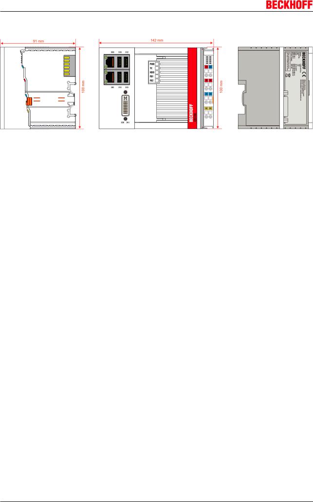
2.4CX5130 Technical data
The basic configuration of the CX5130 contains no storage medium. It must be ordered separately to match the operating system and the application. The basic configuration includes two Ethernet RJ45 interfaces, four USB2.0 interfaces and a DVII interface.
Technical data
Technical data |
CX5130 |
Processor |
Processor: Intel® Atom™ E3827, dualcore, 1.75 |
|
GHz clock frequency (TC3:40) |
Flash memory |
Plugin for CFast card, card not included |
Internal main memory |
4 GB RAM (internal, not extendable) |
Persistent memory |
1second UPS integrated (1MB on CFast card) |
Interfaces |
2 x RJ 45, 10/100/1000 MBit/s, DVII, 4 x USB 2.0, 1x |
|
option interface |
Diagnostic LEDs |
1 x power, 1 x TC status, 1 x flash access, 2 x bus |
|
status |
Clock |
Internal clock with battery backup for time and date |
|
(battery replaceable) |
Operating system |
Microsoft Windows Embedded Standard 7 P |
Control software |
TwinCAT2 PLC runtime or TwinCAT2 NC PTP |
|
runtime |
Power supply |
24 V DC (15 %/+20 %) |
Power supply |
I/O terminals 2 A |
Max. power loss |
12 W (including system interfaces) |
Dielectric strength |
500 Veff (supply/internal electronics) |
Dimensions (W x H x D) |
142 mm x 100 mm x 91 mm |
Weight |
approx. 1095 g |
Operating/storage temperature |
25 °C ... +60 °C / 40 °C ... +85 °C |
Relative humidity |
95 % no condensation |
Vibration/shock resistant |
Conforms to EN 6006826 / EN 60068227 |
EMC immunity/emission |
Conforms to EN 6100062 / EN 6100064 |
Protection class |
IP 20 |
Approvals |
CE |
TC3 performance class |
performance (40) |
Further Information: www.beckhoff.de/CX5100
CX51x0 |
Version 1.0 |
11 |
Product overview
2.5CX5140 Technical data
The basic configuration of the CX5140 contains no storage medium. It must be ordered separately to match the operating system and the application. The basic configuration includes two Ethernet RJ45 interfaces, four USB2.0 interfaces and a DVII interface.
Technical data
Technical data |
CX5140 |
Processor |
Processor: Intel® Atom™ E3845, quadcore, 1.91 |
|
GHz clock frequency (TC3:50) |
Flash memory |
Plugin for CFast card, card not included |
Internal main memory |
4 GB RAM (internal, not extendable) |
Persistent memory |
1second UPS integrated (1MB on CFast card) |
Interfaces |
2 x RJ 45, 10/100/1000 MBit/s, DVII, 4 x USB 2.0, 1x |
|
option interface |
Diagnostic LEDs |
1 x power, 1 x TC status, 1 x flash access, 2 x bus |
|
status |
Clock |
Internal clock with battery backup for time and date |
|
(battery replaceable) |
Operating system |
Microsoft Windows Embedded Standard 7 P |
Control software |
TwinCAT2 PLC runtime or TwinCAT2 NC PTP |
|
runtime |
Power supply |
24 V DC (15 %/+20 %) |
Power supply |
I/O terminals 2 A |
Max. power loss |
14 W (including system interfaces) |
Dielectric strength |
500 Veff (supply/internal electronics) |
Dimensions (W x H x D) |
142 mm x 100 mm x 91 mm |
Weight |
approx. 1095 g |
Operating/storage temperature |
25 °C ... +60 °C / 40 °C ... +85 °C |
Relative humidity |
95 % no condensation |
Vibration/shock resistant |
Conforms to EN 6006826 / EN 60068227 |
EMC immunity/emission |
Conforms to EN 6100062 / EN 6100064 |
Protection class |
IP 20 |
Approvals |
CE |
TC3 performance class |
performance plus (50) |
Further Information: www.beckhoff.de/CX5100
12 |
Version 1.0 |
CX51x0 |
Product overview
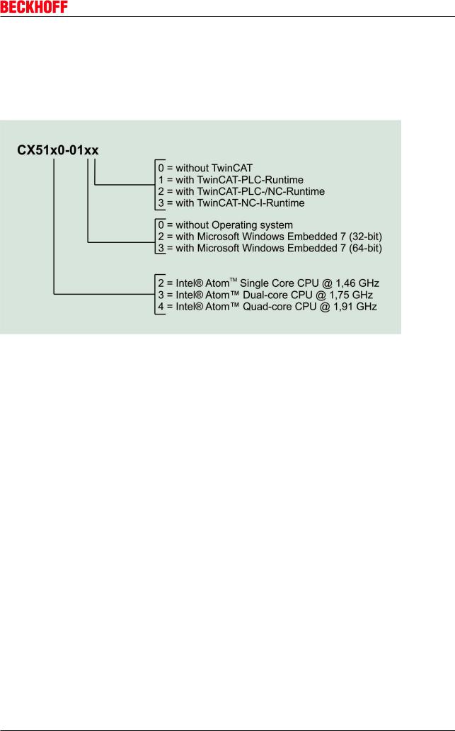
2.6Types
The CPU module can be equipped with different hardware and software options: the operating systems are Windows Embedded Standard 7 in the 32bit or 64bit version. The TwinCAT automation software transforms a CX51x0 system into powerful PLC and Motion Control system that can be operated with or without visualization. Further system interfaces (preinstalled in the factory) or fieldbus connections can be added to the basic CPU module.
The CX 51x0 modules are available in the following types:
CX512001xx:
Module |
Clock fre |
Operating system |
TwinCAT2 runtime |
|
|
Optional |
|||
|
quency |
|
|
|
|
|
|
|
TwinCAT 3 |
|
of |
Windows Embedded |
without |
PLC |
NC PTP |
NC I |
|
||
|
the CPU |
Standard 7 P |
|
TwinCAT |
runtime |
runtime |
runtime |
|
|
|
|
Witho |
32 bit |
64 bit |
|
|
|
|
|
|
|
ut |
|
|
|
|
|
|
|
CX51200100 |
1.46 GHz |
X |
|
|
X |
|
|
|
|
CX51200120 |
1.46 GHz |
|
X |
|
X |
|
|
|
X |
CX51200121 |
1.46 GHz |
|
X |
|
|
X |
|
|
|
CX51200122 |
1.46 GHz |
|
X |
|
|
X |
X |
|
|
CX51200123 |
1.46 GHz |
|
X |
|
X |
X |
X |
X |
|
CX51200130 |
1.46 GHz |
|
|
X |
X |
|
|
|
X |
CX513001xx:
CX51x0 |
Version 1.0 |
13 |
Product overview
Module |
Clock fre |
Operating system |
TwinCAT2 runtime |
|
|
Optional |
|||
|
quency |
|
|
|
|
|
|
|
TwinCAT 3 |
|
of |
Windows Embedded |
without |
PLC |
NC PTP |
NC I |
|
||
|
the CPU |
Standard 7 P |
|
TwinCAT |
runtime |
runtime |
runtime |
|
|
|
|
Witho |
32 bit |
64 bit |
|
|
|
|
|
|
|
ut |
|
|
|
|
|
|
|
CX51300100 |
1.75 GHz |
X |
|
|
X |
|
|
|
|
CX51300120 |
1.75 GHz |
|
X |
|
X |
|
|
|
X |
CX51300121 |
1.75 GHz |
|
X |
|
|
X |
|
|
|
CX51300122 |
1.75 GHz |
|
X |
|
|
X |
X |
|
|
CX51300123 |
1.75 GHz |
|
X |
|
X |
X |
X |
X |
|
CX51300130 |
1.75 GHz |
|
|
X |
X |
|
|
|
X |
CX514001xx: |
|
|
|
|
|
|
|
|
|
|
|
|
|
|
|
||||
Module |
Clock fre |
Operating system |
TwinCAT2 runtime |
|
|
Optional |
|||
|
quency |
|
|
|
|
|
|
|
TwinCAT 3 |
|
of |
Windows Embedded |
without |
PLC |
NC PTP |
NC I |
|
||
|
the CPU |
Standard 7 P |
|
TwinCAT |
runtime |
runtime |
runtime |
|
|
|
|
Witho |
32 bit |
64 bit |
|
|
|
|
|
|
|
ut |
|
|
|
|
|
|
|
CX51400100 |
1.91 GHz |
X |
|
|
X |
|
|
|
|
CX51400120 |
1.91 GHz |
|
X |
|
X |
|
|
|
X |
CX51400121 |
1.91 GHz |
|
X |
|
|
X |
|
|
|
CX51400122 |
1.91 GHz |
|
X |
|
|
X |
X |
|
|
CX51400123 |
1.91 GHz |
|
X |
|
X |
X |
X |
X |
|
CX51400130 |
1.91 GHz |
|
|
X |
X |
|
|
|
X |
CX51x0 systems with Windows Embedded Standard 7 P require a CFast card with a minimum capacity of 8 GB. If TwinCAT3.1 is to be installed with a development environment, a CFast card with a minimum capacity of 16 GB is recommended.
Software Images
A list of the different software images can be found in the CX Software Documentation.
Note
14 |
Version 1.0 |
CX51x0 |

Product overview
2.7Battery compartment
The battery compartment is located under the front cover of the CX51x0. The opening in which the battery bracket is mounted can be seen when the front cover is opened. The battery can be pulled part way out of the opening with the aid of a strap (marked red) until it can be grasped by the fingers and removed from the device.
To insert a new battery push it into the battery compartment. Ensure correct polarity. The battery must be inserted before the strap, to facilitate subsequent removal. Then close the front cover. The battery change is then complete.
The battery is a CR2032 type from Panasonic.
The correct specifications are:
Battery type |
Electrical properties (at |
Standard |
|
Dimensions |
|
|
|
20 °C) |
conditions |
|
|
|
|
|
Nominal volt |
Nominal |
continuous |
Diameter |
Height |
Weight |
|
age |
capacity |
load |
|
|
|
CR2032 |
3.0 V |
225 mAh |
0.20 mA |
20.0 mm |
3.20 mm |
3.1 g |
An incorrectly inserted battery may explode!
Only use the same battery type (CR2032) from Sanyo or Panasonic. It is essential that pos itive and negative terminals of the battery are inserted correctly (negative pole on the left)
Attention Never open the battery or throw it into a fire. The battery cannot be recharged.
Battery maintenance
The battery must be replaced every 5 years. Spare batteries can be ordered from Beckhoff Sales under order number CX19000102.
Note
CX51x0 |
Version 1.0 |
15 |

Product overview
|
The use of alternative batteries would void the UL Listing. |
|
Panasonic batteries were certified as part of the UL Listing. The use of alternative batteries |
Note |
without consulting UL may invalidate the certification. Certified batteries can be ordered |
from Beckhoff Sales. |
16 |
Version 1.0 |
CX51x0 |
Product overview
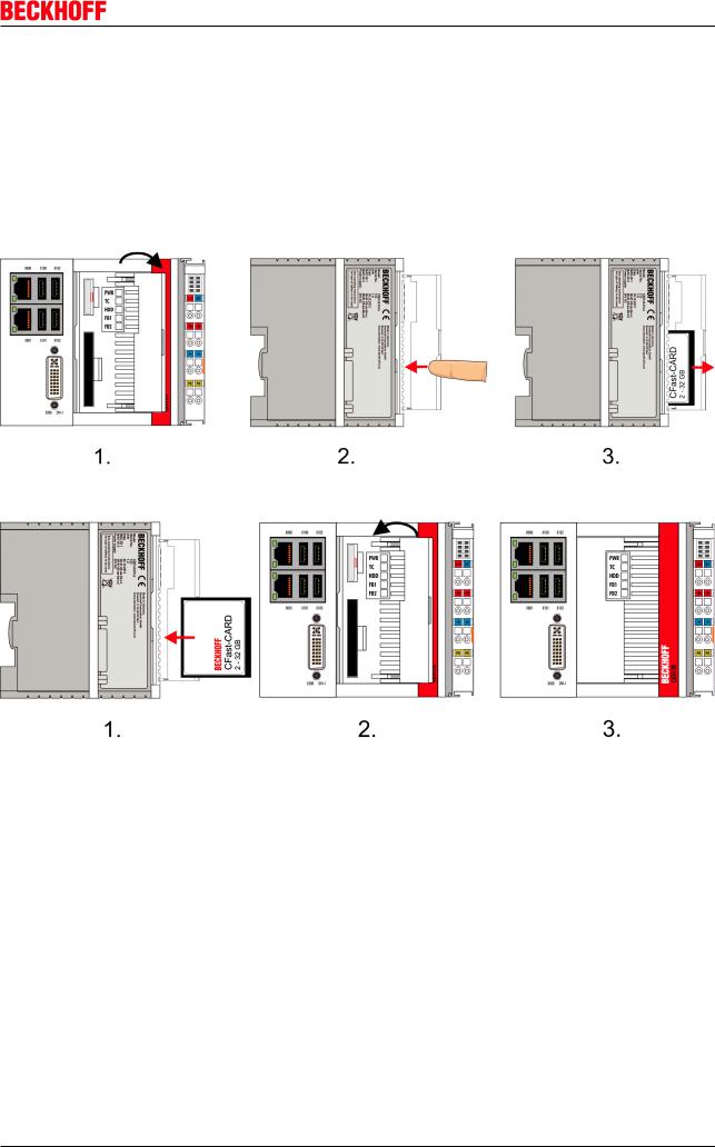
2.8CFast slot
A CFast slot is located at the front. It enables the storage medium to be replaced. In the basic module this should only be done in switchedoff state, otherwise the system may crash. The CFast card can be removed from the module for maintenance. In this way it is also possible to expand the system (only operating system and program memory). CFast cards with different memory sizes are available as accessories.
The following images illustrate the handling of the CFast cards. First, open the front flap. The CFast card slot is then accessible. The eject mechanism is based on the pushpush principle: Pressing the CFast card causes it to be lifted out of the housing by approx. 4 mm, so that it can grasped by the fingers and pulled out.
When the card is pushed back the eject mechanism locks again. The card is positioned correctly, if it is located approx. 1 mm lower than the front of the housing.
Once the flap is closed the device is ready for operation again.
CX51x0 |
Version 1.0 |
17 |

Product overview
2.9CFast card
The CFast card is a nonvolatile storage medium.
In order to store data in a nonvolatile manner, they must be stored on the CFast card.
Using CFast cards
We strongly recommend that only CFast cards supplied by Beckhoff Automation GmbH & Co. KG should be used. These are industrystandard CFast cards with enhanced number Note of write/read cycles and an advanced temperature range (25 °C to +85 °C). Proper opera
tion can only be guaranteed with CFast cards from Beckhoff Automation!
18 |
Version 1.0 |
CX51x0 |
Seconds UPS
3 Seconds UPS
3.1SUPS: capacitive onesecond UPS
The CX51x0 family features a builtin capacitive onesecond UPS. It ensures a safe storage of the persistent application data on the Compact Flash card.
Up to 1 MB of persistent data can be saved. The UPS can be switched on and off via the BIOS. Under the menu:
Advanced > Power Controller Options
the parameter of the SUPS are displayed and can be modified, if required.
Aptio Setup Utility Copyright (C) American Megatrends, Inc.
Bootloader version |
1.0023 |
WatchDogTimer mode |
|
Firmware version |
1.0077 |
|
|
Mainboard serial no |
120003414250178 |
|
|
Mainboard Prod. date (Week.Year) |
44.14 |
|
|
Mainboard BootCount |
4711 |
|
|
Mainboard operation time |
1224min (20h) |
|
|
Voltage (Min/Max) |
5.00V / 5.20V |
|
|
Temperature (Min/Max) |
15°C / 63°C |
|
|
|
|
|
|
USBPort voltage |
[Off in S35] |
|
|
WatchDogTimerMode |
[Compatibility mode] |
|
|
|
|
|
|
1second Uninterruptable Power Supply (SUPS) |
→ ←: Select Screen |
||
|
|
↑ ↓: Select Item |
|
SUPS Enable |
[Enable] |
||
|
|
Enter: Select |
|
Hold Usb |
[Enable] |
||
+/: Change Options |
|||
Delay |
0 |
||
F1: General Help |
|||
|
|
F2: Previous Values |
|
SUPS Firmware version |
1.09 |
F3: Optimized Defaults |
|
F4: Save & Exit |
|||
Current Power source |
On Line |
||
ESC: Quit |
|||
Battery load level |
100% |
||
|
|||
Powerfail counter |
42 |
|
|
|
|
|
|
Version 2.17.1246. Copyright (C) 2014 American Megatrends, Inc.
SUPS Enable
Options: Enable / Disable
Switches the SUPS on or off.
CX51x0 |
Version 1.0 |
19 |

Seconds UPS
Hold USB
Options: Enable / Disable
Switches off the power supply for the USB ports in UPS mode.
Delay
Options: 0…255 seconds
Start delay with which the SUPS is loaded.
SUPS Firmware Version
Firmware version
Current Power Source
Power supply status: Online / Battery
Battery Load Level
Charge state in percent (n% Cap. (n={0...100}) describes the UPS capacity)
Powerfail Counter
Number of power failures
Integration into a PLC
TwinCAT offers special function blocks for integrating the SUPS into a PLC program. These are described below. From TwinCAT 2.11R3 Build 2247 or TwinCAT 3.1 Build 4018 the required library is integrated in the installation. For older versions the library TcSUPS_51x0.lib has to be copied into the TwinCAT library directory.
20 |
Version 1.0 |
CX51x0 |
Seconds UPS
3.2Overview
The library TcSUPS_CX51x0.lib includes functions and function blocks required for controlling the one second UPS. See project example .
Function blocks
Name |
Description |
FB_S_UPS_CX51x0 |
Block for controlling the onesecond UPS |
FB_NT_QuickShutdown |
Internal block for QuickShutdown, used by the |
|
FB_S_UPS. |
Functions
Name |
Description |
F_GetVersionTcSUPS_CX51x0 |
This function can be used to read PLC library version |
|
information. |
|
|
Component |
Version |
TwinCAT on the development PC and on the control |
TwinCAT 2.11R3 Build 2047 or higher |
system |
TwinCAT 3.1 Build 4018 or higher |
3.2.1FUNCTION_BLOCK FB_S_UPS_CX51x0
The function block FB_S_UPS_CX51x0 can be used on CX devices with onesecond UPS to control the onesecond UPS from the PLC. This allows the persistent data to be saved and a quick shutdown to be performed in the event of a power failure. If possible the default values of the INPUTs of the FB_S_UPS_CX51x0 should be retained.
Loss of data
The seconds UPS can be used only for a few seconds in the event of a power failure in or der, to save persistent data. The data must be saved in the fast “persistent mode”
Attention “SPDM_2PASS”, even though this can lead to realtime violations. Sufficient router memory must be configured for the storage of the persistent data!
The second UPS does not have sufficient capacity for bridging power failures. Only the CFast card can be used for data storage, in view of the fact that the UPS capacity is inadequate for operating a hard disk.
A QuickShutdown is performed automatically in the eSUPS_WrPersistData_Shutdown mode (standard setting) after the storage of the persistent data.
In eSUPS_WrPersistData_NoShutdown mode only the persistent data are stored. No QuickShutdown is executed.
In the eSUPS_ImmediateShutdown mode a QuickShutdown is executed immediately without saving data.
CX51x0 |
Version 1.0 |
21 |
Seconds UPS
In the eSUPS_CheckPowerStatus mode only a check is performed as to whether a power failure has occurred. If this is the case, the module only switches back to the PowerOK state after the expiry of tRecoverTime (10s).
Independent of the mode and thus independent of the saving or the shutting down of the controller, the UPS switches the main board off after the capacitors have discharged, even if the voltage has returned in the meantime.
Caution when using files:
If other applications or the PLC keep other files open or write to them, this can lead to faulty files if the UPS switches off the controller.
Attention
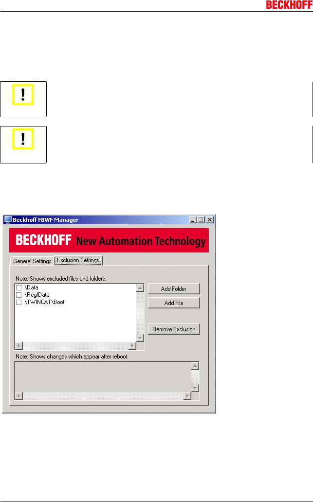
Note regarding Windows Embedded Standard 7 P:
To protect the Windows Embedded Standard 7 P files, either the EWF (Enhanced Write Fil ter) or the FBWF (FileBased Write Filter) must be activated on devices with onesecond
Attention UPS.
If the EWF is used, the TwinCAT\Boot folder must be located on an unprotected partition (see in the registry: HKEY_LOCAL_MACHINE\SOFTWARE\Beckhoff\TwinCAT\System\BootPrjPath).
If the FBWF is used, must the TwinCAT\Boot folder must be excluded from the protection (see Beckhoff FBWF Manager, Exclusion Settings).
FUNCTION_BLOCK FB_S_UPS_CX51x0
VAR_INPUT
VAR_INPUT |
: T_AmsNetId := ''; |
(* '' = |
local netid *) |
|
|||
sNetID |
System for writing persistent data *) |
||||||
iPLCPort |
: UINT := |
AMSPORT_R0_PLC_RTS1; |
(* PLC Runtime |
||||
iUPSPort |
: UINT |
:= |
16#4A8; |
(* Port for |
reading |
Power State of UPS, dafault 16#4A8 *) |
|
tTimeout |
: TIME |
:= |
DEFAULT_ADS_TIMEOUT; |
(* ADS |
Timeout |
*) |
|
22 Version 1.0 CX51x0

|
|
|
Seconds UPS |
eUpsMode |
: E_S_UPS_Mode := eSUPS_WrPersistData_Shutdown; |
(* UPS mode (w/wo writing persistent |
|
data, w/wo shutdown) *) |
|
|
|
ePersistentMode : E_PersistentMode := SPDM_2PASS; (* mode for writing persistent data *) |
|||
tRecoverTime : TIME := T#10s; |
(* ON time to recover |
from short power failure in mode |
|
eSUPS_WrPersistData_NoShutdown/eSUPS_CheckPowerStatus *) END_VAR
E_S_UPS_Mode
sNetID : AmsNetID of the controller.
iPLCPort : Port number of the PLC runtime system (AMSPORT_R0_PLC_RTS1 = 801, AMSPORT_R0_PLC_RTS2 = 811, AMSPORT_R0_PLC_RTS3 = 821, AMSPORT_R0_PLC_RTS4 = 831).
iUPSPort : Port number via which the UPS status is read (standard value is 16#4A8).
tTimeout : Timeout for the execution of the QuickShutdown.
eUpsMode : The eUpsMode defines whether persistent data are to be written and whether a QuickShutdown is to be performed.
Standard value is eSUPS_WrPersistData_Shutdown, i.e. with writing of the persistent data and then QuickShutdown. See E_S_UPS_Mode.
ePersistentMode : Mode for the writing of the persistent data. Standard value is SPDM_2PASS.
tRecoverTime : Time after which the UPS reverts to the PowerOK status in the case of UPS modes without shutdown.
The tRecoverTime must be somewhat longer than the maximum holding time of the UPS, since the UPS switches off even when the voltage returns.
VAR_OUTPUT
VAR_OUTPUT |
|
: BOOL; |
(* TRUE while powerfailure is detected *) |
bPowerFailDetect |
|||
eState |
: E_S_UPS_State; (* current ups state *) |
||
END_VAR |
|
|
|
|
|
|
|
E_S_UPS_State
bPowerFailDetect : True during the power failure; False if the supply voltage is present.
eState : Internal state of the function block, for values see E_S_UPS_State.
VAR_GLOBAL
VAR_GLOBAL
eGlobalSUpsState : E_S_UPS_State; (* current ups state *) END_VAR
E_S_UPS_State
eGlobalUpsState : Internal state of the function block as a global copy of the VAR_OUTPUT eState; for values see E_S_UPS_State.
Prerequisites
Development environment |
Target plat |
Hardware |
PLC libraries to include |
|
form |
|
|
TwinCAT v2.11R3 Build 2047 or higher |
PC (i386) |
Seconds UPS |
TcSUPS_CX51x0.Lib |
TwinCAT 3.1 Build 4018 or higher |
|
|
|
CX51x0 |
Version 1.0 |
23 |

Seconds UPS
3.2.2FUNCTION_BLOCK FB_NT_QuickShutdown
The function block FB_NT_QuickShutdown can be used to trigger an immediate reboot, without stopping TwinCAT or the Windows operating system.
Attention:
Loss of data
The function block FB_NT_QuickShutdown is used internally by FB_S_UPS_CX51x0. It must not be used independently, because this could result in data loss!
Attention
FUNCTION_BLOCK FB_NT_QuickShutdown
VAR_INPUT
VAR_INPUT
NETID :T_AmsNetId;
START :BOOL;
TMOUT :TIME := DEFAULT_ADS_TIMEOUT;
END_VAR
NETID : AmsNetID of the controller.
START : Rising edge leads to immediate reboot of the control system.
TMOUT : Time out period.
VAR_OUTPUT
VAR_OUTPUT
BUSY :BOOL;
ERR :BOOL;
ERRID :UDINT;
END_VAR
BUSY : QuickShutdown is executed.
ERR : Becomes TRUE, as soon as an error occurs.
ERRID : Supplies the error number when the ERR output is set.
Prerequisites
Development environment |
Target plat |
Hardware |
PLC libraries to include |
|
form |
|
|
TwinCAT v2.11R3 Build 2047 or higher |
PC (i386) |
Onesecond UPS |
TcSUPS_CX51x0.Lib |
TwinCAT 3.1 Build 4018 or higher |
|
|
|
24 |
Version 1.0 |
CX51x0 |

Seconds UPS
3.3Functions
3.3.1FUNCTION F_GetVersionTcSUPS_CX51x0
This function can be used to read PLC library version information.
FUNCTION F_GetVersionTcSUPS_CX51x0 : UINT
VAR_INPUT
nVersionElement : INT; END_VAR
nVersionElement : Version element to be read. Possible parameters:
•1 : major number
•2 : minor number
•3 : revision number
Prerequisites
Development environment |
Target plat |
Hardware |
PLC libraries to include |
|
form |
|
|
TwinCAT v2.11R3 Build 2047 or higher |
PC (i386) |
Seconds UPS |
TcSUPS_CX51x0.Lib |
TwinCAT v3.1 Build 4018 or higher |
|
|
|
CX51x0 |
Version 1.0 |
25 |

Seconds UPS
3.4Data Types
3.4.1TYPE E_S_UPS_Mode
eSUPS_WrPersistData_Shutdown: write persistent data and then QuickShutdown
eSUPS_WrPersistData_NoShutdown: write persistent data only (no QuickShutdown)
eSUPS_ImmediateShutdown: QuickShutdown only (no writing of persistent data)
eSUPS_CheckPowerStatus: determine status only (neither write persistent data nor QuickShutdown)
Prerequisites
Development environment |
Target plat |
Hardware |
PLC libraries to include |
|
form |
|
|
TwinCAT v2.11R3 Build 2047 or higher |
PC (i386) |
Seconds UPS |
TcSUPS_CX51x0.Lib |
TwinCAT v3.1 Build 4018 or higher |
|
|
|
3.4.2TYPE E_S_UPS_State
eSUPS_PowerOK:
in all modes: supply voltage is OK
eSUPS_PowerFailure:
in all modes: Supply voltage faulty (applied for one cycle only)
eSUPS_WritePersistentData:
in eSUPS_WrPersistData_Shutdown mode: writing of the persistent data is active in eSUPS_WrPersistData_NoShutdown mode: writing of the persistent data is active
eSUPS_QuickShutdown:
in eSUPS_WrPersistData_Shutdown mode: QuickShutdown is active in eSUPS_ImmediateShutdown mode: QuickShutdown is active
eSUPS_WaitForRecover:
in eSUPS_WrPersistData_NoShutdown mode: wait for return of the voltage in eSUPS_CheckPowerStatus mode: wait for return of the voltage
eSUPS_WaitForPowerOFF:
in eSUPS_WrPersistData_Shutdown mode: wait for shutdown by the UPS in eSUPS_ImmediateShutdown mode: wait for shutdown by the UPS
Prerequisites
Development environment |
Target plat |
Hardware |
PLC libraries to include |
|
form |
|
|
TwinCAT v2.11R3 Build 2047 or higher |
PC (i386) |
Seconds UPS |
TcSUPS_CX51x0.Lib |
TwinCAT v3.1 Build 4018 or higher |
|
|
|
26 |
Version 1.0 |
CX51x0 |

Mounting and wiring
4 Mounting and wiring
4.1Unpacking, installation and transport
The specified storage conditions must be adhered to (see "Technical data").
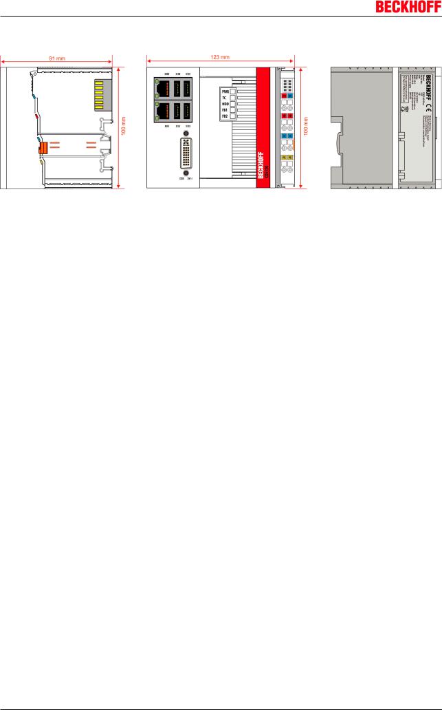
Dimensions and weight of the individual modules:
CX512001xx:
Dimensions (W x H x D): 123 mm x 100 mm x 91 mm
Weight: approx. 975 g
CX513001xx:
Dimensions (W x H x D): 142 mm x 100 mm x 91 mm
Weight: approx. 1095 g
CX514001xx:
Dimensions (W x H x D): 142 mm x 100 mm x 91 mm
Weight: approx. 1095 g
Unpacking
Proceed as follows to unpack the unit:
1.Remove packaging.
2.Do not discard the original packaging. Keep it for transporting the device in the future.
3.Check the delivery for completeness by comparing it with your order.
4.Please keep the associated paperwork. It contains important information for handling the unit.
5.Check the contents for visible shipping damage.
6.If you notice any shipping damage or inconsistencies between the contents and your order, you should notify Beckhoff Service.
Danger of damage to the device!
During transport in cold conditions, or if the device is subjected to extreme temperature dif ferences, condensation on and inside the device must be avoided. Prior to operation, the
Attention device must be allowed to slowly adjust to room temperature. Should condensation occur, a delay time of approximately 12 hours must be allowed before the unit is switched on.
Installation
The devices are designed for installation in control cabinets.
Shipping and relocation
Despite the robust design of the unit, the components are sensitive to strong vibrations and impacts. During transport, your computer should therefore be protected from excessive mechanical stress. Therefore, please use the original packaging.
CX51x0 |
Version 1.0 |
27 |
Loading...