


 Loading...
Documentation
Synchronous Servomotor AM3000 and AM3500
Version: 1.5
Date: 2015-03-10

Documented motors  Drive Technology
Documented motors
|
|
|
Rated speed at rated supply |
Rotor moment of inertia |
Weight |
Weight |
||||
AM3tuv-wxyz |
Standstill |
Standstill |
voltage |
|
|
|||||
|
|
|
|
|
|
|||||
torque |
current |
230 V AC |
400 V AC |
480 V AC |
without |
with |
without |
with |
||
|
||||||||||
|
|
|
brake |
brake |
brake |
brake |
||||
|
|
|
|
|
|
|||||
AM3011-wB00 |
0.18Nm |
1.16 A |
8000 min-1 |
- |
- |
0,017 kg cm² |
0,021 kg cm² |
0,35 kg |
0,55 kg |
|
AM3012-wC00 |
0.31Nm |
1.51 A |
8000 min-1 |
- |
- |
0,031 kg cm² |
0,035 kg cm² |
0,49 kg |
0,69 kg |
|
AM3013-wC00 |
0.41Nm |
1.48 A |
8000 min-1 |
- |
- |
0,045 kg cm² |
0,049 kg cm² |
0,63 kg |
0,83 kg |
|
AM3021-wCyz |
0.48 Nm |
1.58 A |
8000 min-1 |
- |
- |
0.107 kg cm² |
0.118 kg cm² |
0.82 kg |
1.09 kg |
|
AM3022-WCyz |
0.84 Nm |
1.39 A |
3500 min-1 |
8000 min-1 |
8000 min-1 |
0.161 kg cm² |
0.172 kg cm² |
1.10 kg |
1.37 kg |
|
AM3023-wCyz |
1.13Nm |
1.41 A |
2500 min-1 |
5500 min-1 |
7000 min-1 |
0.216 kg cm² |
0.227 kg cm² |
1.38 kg |
1.65 kg |
|
AM3024-wCyz |
1.38Nm |
1.42 A |
2000 min-1 |
4500 min-1 |
5500 min-1 |
0.270 kg cm² |
0.281 kg cm² |
1.66 kg |
1.93 kg |
|
AM3024-wDyz |
1.41 Nm |
2.21 A |
4000 min-1 |
8000 min-1 |
8000 min-1 |
0.270 kg cm² |
0.281 kg cm² |
1.66 kg |
1.93 kg |
|
AM3031-wCyz |
1.15 Nm |
1.37 A |
2500 min-1 |
5000 min-1 |
6000 min-1 |
0.330 kg cm² |
0.341 kg cm² |
1.55 kg |
1.90 kg |
|
AM3031-wEyz |
1.20 Nm |
2.99 A |
6000 min-1 |
- |
- |
0.330 kg cm² |
0.341 kg cm² |
1.55 kg |
1.90 kg |
|
AM3032-wCyz |
2.00 Nm |
1.44 A |
1500 min-1 |
3000 min-1 |
3500 min-1 |
0.590 kg cm² |
0.601 kg cm² |
2.23 kg |
2.58 kg |
|
AM3032-wDyz |
2.04 Nm |
2.23 A |
2500 min-1 |
5500 min-1 |
6000 min-1 |
0.590 kg cm² |
0.601 kg cm² |
2.23 kg |
2.58 kg |
|
AM3033-wCyz |
2.71 Nm |
1.47 A |
1000 min-1 |
2000 min-1 |
2500 min-1 |
0.850 kg cm² |
0.861 kg cm² |
2.90 kg |
3.25 kg |
|
AM3033.wEyz |
2.79 Nm |
2.58 A |
2000 min-1 |
4500 min-1 |
5000 min-1 |
0.850 kg cm² |
0.861 kg cm² |
2.90 kg |
3.25 kg |
|
AM3041-wCyz |
1.95 Nm |
1.46 A |
1200 min-1 |
3000 min-1 |
3500 min-1 |
0.810 kg cm² |
0.878 kg cm² |
2.44 kg |
3.07 kg |
|
AM3041-wEyz |
2.02 Nm |
2.85 A |
3000 min-1 |
6000 min-1 |
6000 min-1 |
0.810 kg cm² |
0.878 kg cm² |
2.44 kg |
3.07 kg |
|
AM3042-wEyz |
3.42 Nm |
2.74 A |
1800 min-1 |
3500 min-1 |
4000 min-1 |
1.450 kg cm² |
1.518 kg cm² |
3.39 kg |
4.02 kg |
|
AM3042-wGyz |
3.53 Nm |
4.80 A |
3500 min-1 |
6000 min-1 |
6000 min-1 |
1.450 kg cm² |
1.518 kg cm² |
3.39 kg |
4.02 kg |
|
AM3043-wEyz |
4.70 Nm |
2.76 A |
1500 min-1 |
2500 min-1 |
3000 min-1 |
2.090 kg cm² |
2.158 kg cm² |
4.35 kg |
4.98 kg |
|
AM3043-wGyz |
4.80 Nm |
4.87 A |
2500 min-1 |
5000 min-1 |
6000 min-1 |
2.090 kg cm² |
2.158 kg cm² |
4.35 kg |
4.98 kg |
|
AM3043-wHyz |
4.82 Nm |
5.4 A |
3000 min-1 |
6000 min-1 |
- |
2.090 kg cm² |
2.158 kg cm² |
4.35 kg |
4.98 kg |
|
AM3044-wEyz |
5.76 Nm |
2.90 A |
1200 min-1 |
2500 min-1 |
2500 min-1 |
2.730 kg cm² |
2.798 kg cm² |
5.30 kg |
5.93 kg |
|
AM3044-wGyz |
5.88 Nm |
5.00 A |
2000 min-1 |
4000 min-1 |
5000 min-1 |
2.730 kg cm² |
2.798 kg cm² |
5.30 kg |
5.93 kg |
|
AM3044-wHyz |
5.89 Nm |
5.6 A |
2500 min-1 |
5000 min-1 |
6000 min-1 |
2.730 kg cm² |
2.798 kg cm² |
5.30 kg |
5.93 kg |
|
AM3044-wJyz |
6.00 Nm |
8.80 A |
4000 min-1 |
6000 min-1 |
6000 min-1 |
2.730 kg cm² |
2.798 kg cm² |
5.30 kg |
5.93 kg |
|
AM3051-wEyz |
4.70 Nm |
2.75 A |
1200 min-1 |
2500 min-1 |
3000 min-1 |
3.420 kg cm² |
3.593 kg cm² |
4.20 kg |
5.30 kg |
|
AM3051-wGyz |
4.75 Nm |
4.84 A |
2500 min-1 |
5000 min-1 |
6000 min-1 |
3.420 kg cm² |
3.593 kg cm² |
4.20 kg |
5.30 kg |
|
AM3051-wHyz |
4.79 Nm |
6.00 A |
3000 min-1 |
6000 min-1 |
6000 min-1 |
3.420 kg cm² |
3.593 kg cm² |
4.20 kg |
5.30 kg |
|
AM3052-wGyz |
8.43 Nm |
4.72 A |
1500 min-1 |
2500 min-1 |
3000 min-1 |
6.220 kg cm² |
6.393 kg cm² |
5.80 kg |
6.90 kg |
|
AM3052-wHyz |
8.48 Nm |
5.9 A |
1800 min-1 |
3500 min-1 |
4000 min-1 |
6.220 kg cm² |
6.393 kg cm² |
5.80 kg |
6.90 kg |
|
AM3052-wKyz |
8.60 Nm |
9.30 A |
3000 min-1 |
5500 min-1 |
6000 min-1 |
6.220 kg cm² |
6.393 kg cm² |
5.80 kg |
6.90 kg |
|
AM3053-wGyz |
11.37Nm |
4.77 A |
1000 min-1 |
2000 min-1 |
2400 min-1 |
9.120 kg cm² |
9.293 kg cm² |
7.40 kg |
8.50 kg |
|
Am3053-wHyz |
11.51 Nm |
6.60 A |
- |
3000 min-1 |
3500 min-1 |
9.120 kg cm² |
9.293 kg cm² |
7.40 kg |
8.50 kg |
|
AM3053-wKyz |
11.60 Nm |
9.40 A |
2000 min-1 |
4000 min-1 |
4500 min-1 |
9.120 kg cm² |
9.293 kg cm² |
7.40 kg |
8.50 kg |
|
AM3054-wHyz |
14.90 Nm |
5.50 A |
1000 min-1 |
1800 min-1 |
2000 min-1 |
12.92 kg cm² |
12.093 kg cm² |
9.00 kg |
10.10 kg |
|
2 |
Version: 1.5 |
AM3000 / AM3500 |

|
Drive Technology |
|
|
|
|
Documented motors |
||||||
|
|
|
|
|
|
|
|
|
|
|
|
|
|
|
|
Rated speed at rated supply |
Rotor moment of inertia |
Weight |
Weight |
||||||
AM3tuv-wxyz |
Standstill |
Standstill |
voltage |
|
|
|||||||
|
|
|
|
|
|
|
|
|||||
torque |
current |
230 V AC |
400 V AC |
480 V AC |
without |
with |
without |
with |
||||
|
||||||||||||
|
|
|
|
|
|
brake |
brake |
brake |
brake |
|||
AM3054-wKyz |
14.40 Nm |
9.70 A |
1800 min-1 |
3500 min-1 |
4000 min-1 |
11.92 kg cm² |
12.093 kg cm² |
9.00 kg |
10.10 kg |
|||
AM3062-wHyz |
11.90 Nm |
5.40 A |
1000 min-1 |
2000 min-1 |
2400 min-1 |
16.90 kg cm² |
17.51 kg cm² |
8.90 kg |
10.90 kg |
|||
AM3062-wKyz |
12.20 Nm |
9.60 A |
2000 min-1 |
3500 min-1 |
4500 min-1 |
16.90 kg cm² |
17.51 kg cm² |
8.90 kg |
10.90 kg |
|||
AM3062-wMyz |
12.20 Nm |
13.40 A |
3000 min-1 |
6000 min-1 |
6000 min-1 |
16.90 kg cm² |
17.51 kg cm² |
8.90 kg |
10.90 kg |
|||
AM3063-wKyz |
16.80Nm |
9.90 A |
1500 min-1 |
3000 min-1 |
3500 min-1 |
24.20 kg cm² |
24.81 kg cm² |
11.10 kg |
13.10 kg |
|||
AM3063-wMyz |
17.00 Nm |
13.80 A |
2000 min-1 |
4000 min-1 |
4500 min-1 |
24.20 kg cm² |
24.81 kg cm² |
11.10 kg |
13.10 kg |
|||
AM3063-wNyz |
17.00 Nm |
17.40 A |
3000 min-1 |
5000 min-1 |
6000 min-1 |
24.20 kg cm² |
24.81 kg cm² |
11.10 kg |
13.10 kg |
|||
AM3064-wHyz |
16.60 Nm |
5.60 A |
- |
1500 min-1 |
1800 min-1 |
31.60 kg cm² |
32.21 kg cm² |
13.30 kg |
15.30 kg |
|||
AM3064-wKyz |
20.80 Nm |
9.20 A |
1200 min-1 |
2000 min-1 |
2500 min-1 |
31.60 kg cm² |
32.21 kg cm² |
13.30 kg |
15.30 kg |
|||
AM3064-wLyz |
21.00 Nm |
12.80A |
1500 min-1 |
3000 min-1 |
3500 min-1 |
31.60 kg cm² |
32.21 kg cm² |
13.30 kg |
15.30 kg |
|||
AM3064-wPyz |
20.40 Nm |
18.60 A |
2500 min-1 |
4500 min-1 |
5500 min-1 |
31.60 kg cm² |
32.21 kg cm² |
13.30 kg |
15.30 kg |
|||
AM3065-wKyz |
24.80 Nm |
9.80 A |
1000 min-1 |
2000 min-1 |
2200 min-1 |
40.00 kg cm² |
40.61 kg cm² |
15.40 kg |
17.40 kg |
|||
AM3065-wMyz |
25.00 Nm |
13.60 A |
1500 min-1 |
2500 min-1 |
3000 min-1 |
40.00 kg cm² |
40.61 kg cm² |
15.40 kg |
17.40 kg |
|||
AM3065-wNyz |
24.30 Nm |
17.80 A |
2000 min-1 |
3500 min-1 |
4000 min-1 |
40.00 kg cm² |
40.61 kg cm² |
15.40 kg |
17.40 kg |
|||
AM3065-wPyz |
24.50 Nm |
19.80 A |
3000 min-1 |
4000 min-1 |
5000 min-1 |
40.00 kg cm² |
40.61 kg cm² |
15.40 kg |
17.40 kg |
|||
AM3072-wKyz |
27.70 Nm |
9.30 A |
- |
1500 min-1 |
1800 min-1 |
64.50 kg cm² |
66.14 kg cm² |
19.70 kg |
21.80 kg |
|||
AM3072.wMyz |
30.00 Nm |
13.00 A |
- |
2000 min-1 |
2500 min-1 |
64.50 kg cm² |
66.14 kg cm² |
19.70 kg |
21.80 kg |
|||
AM3072-wPyz |
29.40 Nm |
18.70 A |
1800 min-1 |
3000 min-1 |
3500 min-1 |
64.50 kg cm² |
66.14 kg cm² |
19.70 kg |
21.80 kg |
|||
AM3072-wQyz |
29.70 Nm |
20.90 A |
- |
3500 min-1 |
4000 min-1 |
64.50 kg cm² |
66.14 kg cm² |
19.70 kg |
21.80 kg |
|||
AM3073-wMyz |
42.00 Nm |
13.60 A |
- |
1500 min-1 |
1800 min-1 |
92.10 kg cm² |
93.74 kg cm² |
26.70 kg |
28.80 kg |
|||
AM3073-wMyz |
41.60 Nm |
19.50 A |
1300 min-1 |
2400 min-1 |
2800 min-1 |
92.10 kg cm² |
93.74 kg cm² |
26.70 kg |
28.80 kg |
|||
AM3073-wQyz |
41.60 Nm |
24.60 A |
- |
2500 min-1 |
3000 min-1 |
92.10 kg cm² |
93.74 kg cm² |
26.70 kg |
28.80 kg |
|||
AM3074-wLyz |
53.00 Nm |
12.90 A |
- |
1200 min-1 |
1400 min-1 |
119.70 kg cm² |
121.64 kg cm² |
33.60 kg |
35.70 kg |
|||
AM3074-wPyz |
52.50 Nm |
18.50 A |
- |
1800 min-1 |
2000 min-1 |
119.70 kg cm² |
121.64 kg cm² |
33.60 kg |
35.70 kg |
|||
AM3074-wQyz |
51.90 Nm |
26.20 A |
- |
2500 min-1 |
3000 min-1 |
119.70 kg cm² |
121.64 kg cm² |
33.60 kg |
35.70 kg |
|||
AM3082-wTyz |
75.00 Nm |
48.00 A |
- |
2500 min-1 |
3000 |
172 kg cm² |
177.53 |
65 kg |
73 |
|||
AM3083-wTyz |
130.00 Nm |
62.00 A |
- |
2200 min-1 |
2500 |
334 kg cm² |
339.53 |
85 kg |
93 |
|||
AM3084-wTyz |
180.00 Nm |
67.00 A |
- |
1800 min-1 |
2000 |
495 kg cm² |
500.53 |
105 kg |
113 |
|||
AM3541-w0yz |
1.9 Nm |
1.7 A |
- |
3000 min-1 |
- |
2.0 kg cm² |
2.2 kg cm² |
2.4 kg |
3.0 kg |
|||
AM3541-w1yz |
1.9 Nm |
2.8 A |
- |
6000 min-1 |
- |
2.0 kg cm² |
2.2 kg cm² |
2.4 kg |
3.0 kg |
|||
AM3542-w0yz |
3.3 Nm |
2.4 A |
- |
3000 min-1 |
- |
4.0 kg cm² |
4.2 kg cm² |
3.8 kg |
4.4 kg |
|||
AM3542-w1yz |
3.3 Nm |
4.5 A |
- |
6000 min-1 |
- |
4.0 kg cm² |
4.2 kg cm² |
3.8 kg |
4.4 kg |
|||
AM3543-w0yz |
4.2 Nm |
3.0 A |
- |
3000 min-1 |
- |
8.0 kg cm² |
8.2 kg cm² |
5.35 kg |
5.9 kg |
|||
AM3543-w1yz |
4.2 Nm |
5.2 A |
- |
6000 min-1 |
- |
8.0 kg cm² |
8.2 kg cm² |
5.35 kg |
5.9 kg |
|||
AM3551-w0yz |
4.1 Nm |
3.4 A |
- |
3000 min-1 |
- |
15.0 kg cm² |
15.6 kg cm² |
5.8 kg |
6.6 kg |
|||
AM3551-w1yz |
4.1 Nm |
6.1 A |
- |
6000 min-1 |
- |
15.0 kg cm² |
15.6 kg cm² |
5.8 kg |
6.6 kg |
|||
AM3552-w0yz |
6.3 Nm |
4.8 A |
- |
3000 min-1 |
- |
19.0 kg cm² |
19.6 kg cm² |
7.0 kg |
7.8 kg |
|||
|
|
|
|
|
|
|
|
|
|
|
|
|
AM3000 / AM3500 |
Version: 1.5 |
3 |

Documented motors |
|
|
|
|
|
Drive Technology |
|||||
|
|
|
|
|
|
|
|
|
|
|
|
|
|
|
Rated speed at rated supply |
Rotor moment of inertia |
Weight |
Weight |
|||||
AM3tuv-wxyz |
Standstill |
Standstill |
voltage |
|
|
||||||
|
|
|
|
|
|
|
|||||
torque |
current |
230 V AC |
400 V AC |
480 V AC |
without |
with |
without |
with |
|||
|
|||||||||||
|
|
|
|
|
|
brake |
brake |
brake |
brake |
||
AM3553-w0yz |
8.6 Nm |
6.4 A |
- |
3000 min-1 |
- |
20.0 kg cm² |
20.6 kg cm² |
8.9 kg |
9.7 kg |
||
AM3562-w0yz |
11.6 Nm |
10.3 A |
- |
3000 min-1 |
- |
40.0 kg cm² |
42.0 kg cm² |
10.7 kg |
11.8 kg |
||
AM3563-w0yz |
14.9 Nm |
12.5 A |
- |
3000 min-1 |
- |
60.0 kg cm² |
62.0 kg cm² |
13.6 kg |
14.7 kg |
||
4 |
Version: 1.5 |
AM3000 / AM3500 |

|
Drive Technology |
Table of contents – AM3000 and AM3500 |
|
Chapter |
|
|
Page |
Table of contents – AM3000 and AM3500 |
|
||
Documented motors............................................................................................................................................. |
|
2 |
|
Table of contents – AM3000 and AM3500 .......................................................................................................... |
|
5 |
|
1 |
Foreword ................................................................................................................................................ |
|
7 |
1.1 |
Notes on the documentation .......................................................................................................... |
|
7 |
1.2 |
Disclaimer ...................................................................................................................................... |
|
7 |
1.3 |
Brands ............................................................................................................................................ |
|
7 |
1.4 |
Patents ........................................................................................................................................... |
|
7 |
1.5 |
Copyright........................................................................................................................................ |
|
7 |
1.6 |
Documentation issue status........................................................................................................... |
|
7 |
1.7 |
Appropriate use.............................................................................................................................. |
|
8 |
2 |
Guidelines and Standards ................................................................................................................... |
|
9 |
2.1 |
EC declaration of conformity.......................................................................................................... |
|
9 |
3 |
Safety.................................................................................................................................................... |
|
10 |
3.1 |
General safety instructions .......................................................................................................... |
|
10 |
3.1.1 |
Personnel qualification ................................................................................................................. |
|
10 |
3.1.2 |
Description of safety symbols ...................................................................................................... |
|
10 |
3.2 |
Special safety instructions for AM3000 and AM3500 .................................................................. |
11 |
|
4 |
Handling ............................................................................................................................................... |
|
12 |
4.1 |
Transport...................................................................................................................................... |
|
12 |
4.2 |
Packaging .................................................................................................................................... |
|
12 |
4.3 |
Storage......................................................................................................................................... |
|
12 |
4.4 |
Maintenance / Cleaning ............................................................................................................... |
|
12 |
4.5 |
Disposal ....................................................................................................................................... |
|
13 |
5 |
Product identification ........................................................................................................................ |
|
14 |
5.1 |
AM3000, scope of supply............................................................................................................. |
|
14 |
5.2 |
AM3000 nameplate ...................................................................................................................... |
|
14 |
5.3 |
AM3000 type key ......................................................................................................................... |
|
14 |
5.4 |
AM3500, scope of supply............................................................................................................. |
|
15 |
5.5 |
AM3500 nameplate ...................................................................................................................... |
|
15 |
5.6 |
AM3500 type key ......................................................................................................................... |
|
15 |
6 |
Technical description ........................................................................................................................ |
|
16 |
6.1 |
Design of the motors .................................................................................................................... |
|
16 |
6.2 |
General technical data ................................................................................................................. |
|
16 |
6.3 |
Standard features......................................................................................................................... |
|
17 |
6.3.1 |
Style ............................................................................................................................................. |
|
17 |
6.3.2 |
Shaft end, A-side.......................................................................................................................... |
|
17 |
6.3.3 |
Flange .......................................................................................................................................... |
|
17 |
6.3.4 |
Protection class............................................................................................................................ |
|
17 |
6.3.5 |
Overtemperature protection ......................................................................................................... |
|
17 |
6.3.6 |
Insulation material class............................................................................................................... |
|
17 |
6.3.7 |
Vibration class.............................................................................................................................. |
|
18 |
6.3.8 |
Connection technology................................................................................................................. |
|
18 |
6.3.9 |
Feedback unit............................................................................................................................... |
|
18 |
6.3.10 |
Holding brake ............................................................................................................................... |
|
18 |
6.3.11 |
Pole numbers ............................................................................................................................... |
|
19 |
6.4 |
Options......................................................................................................................................... |
|
19 |
6.5 |
Selection criteria........................................................................................................................... |
|
19 |
7 |
Mechanical installation ....................................................................................................................... |
|
20 |
7.1 |
Important notes ............................................................................................................................ |
|
20 |
8 |
Electrical installation........................................................................................................................... |
|
21 |
8.1 |
Important notes ............................................................................................................................ |
|
21 |
8.2 |
Connection of motors with pre-assembled cables ....................................................................... |
22 |
|
8.2.1 |
AX5000 ........................................................................................................................................ |
|
22 |
8.2.2 |
AX2000 and AX2500.................................................................................................................... |
|
26 |
8.3 |
AX5000 connection diagram for motors with EnDAT / BiSS encoder ......................................... |
29 |
|
AM3000 / AM3500 |
Version: 1.5 |
5 |
|

Table of contents – AM3000 and AM3500 |
Drive Technology |
||
8.4 |
|
AX5000 connection diagram for motors with resolver ................................................................. |
30 |
8.5 |
|
AX5000 connection diagram for motors with resolver and yTec-Plug......................................... |
31 |
8.6 |
|
AX2000 connection diagram for motors with EnDAT / BiSS encoder ......................................... |
32 |
8.7 |
|
AX2000 connection diagram for motors with resolver ................................................................. |
33 |
9 |
Commissioning.................................................................................................................................... |
34 |
|
9.1 |
|
Important notes ............................................................................................................................ |
34 |
9.2 |
|
Guide for commissioning.............................................................................................................. |
34 |
9.3 |
|
Troubleshooting ........................................................................................................................... |
34 |
10 |
Technical data...................................................................................................................................... |
36 |
|
10.1 |
|
Term definitions............................................................................................................................ |
36 |
10.2 |
|
AM301x ........................................................................................................................................ |
37 |
10.2.1A |
Dimensional drawing.................................................................................................................... |
38 |
|
10.2.1B |
Dimensional drawing.................................................................................................................... |
38 |
|
10.2.2 |
|
Radial / axial forces at the shaft end............................................................................................ |
39 |
10.2.3 |
|
Characteristic torque / speed curves ........................................................................................... |
39 |
10.3 |
|
AM302x ........................................................................................................................................ |
40 |
10.3.1 |
|
Dimensional drawing.................................................................................................................... |
41 |
10.3.2 |
|
Radial / axial forces at the shaft end............................................................................................ |
41 |
10.3.3 |
|
Characteristic torque / speed curves ........................................................................................... |
41 |
10.4 |
|
AM303x ........................................................................................................................................ |
42 |
10.4.1 |
|
Dimensional drawing.................................................................................................................... |
43 |
10.4.2 |
|
Radial / axial forces at the shaft end............................................................................................ |
43 |
10.4.3 |
|
Characteristic torque / speed curves ........................................................................................... |
43 |
10.5 |
|
AM304x ........................................................................................................................................ |
44 |
10.5.1 |
|
Dimensional drawing.................................................................................................................... |
45 |
10.5.2 |
|
Radial / axial forces at the shaft end............................................................................................ |
45 |
10.5.3 |
|
Characteristic torque / speed curves ........................................................................................... |
45 |
10.6A |
|
AM305x (AM3051; AM3052)........................................................................................................ |
46 |
10.6B |
|
AM305x(AM3053 and AM3054)................................................................................................... |
47 |
10.6.1 |
|
Dimensional drawing.................................................................................................................... |
48 |
10.6.2 |
|
Radial / axial forces at the shaft end............................................................................................ |
48 |
10.6.3 |
|
Characteristic torque / speed curves ........................................................................................... |
48 |
10.7 |
|
AM306x ........................................................................................................................................ |
49 |
10.7.1 |
|
Dimensional drawing.................................................................................................................... |
50 |
10.7.2 |
|
Radial / axial forces at the shaft end............................................................................................ |
50 |
10.7.3 |
|
Characteristic torque / speed curves ........................................................................................... |
50 |
10.8 |
|
AM307x ........................................................................................................................................ |
51 |
10.8.1 |
|
Dimensional drawing.................................................................................................................... |
52 |
10.8.2 |
|
Radial / axial forces at the shaft end............................................................................................ |
52 |
10.8.3 |
|
Characteristic torque / speed curves ........................................................................................... |
52 |
10.9 |
|
AM308x ........................................................................................................................................ |
53 |
10.9.1 |
|
Dimensional drawing.................................................................................................................... |
54 |
10.9.2 |
|
Radial / axial forces at the shaft end............................................................................................ |
55 |
10.9.3 |
|
Characteristic torque / speed curves ........................................................................................... |
55 |
10.10 |
|
AM354x ........................................................................................................................................ |
56 |
10.10.1 |
Dimensional drawing.................................................................................................................... |
57 |
|
10.10.2 |
Characteristic torque / speed curves ........................................................................................... |
58 |
|
10.11 |
|
AM355x ........................................................................................................................................ |
59 |
10.11.1 |
Dimensional drawing.................................................................................................................... |
60 |
|
10.11.2 |
Characteristic torque / speed curves ........................................................................................... |
61 |
|
10.12 |
|
AM356x ........................................................................................................................................ |
62 |
10.12.1 |
Dimensional drawing.................................................................................................................... |
63 |
|
10.12.2 |
Characteristic torque / speed curves ........................................................................................... |
64 |
|
11 |
Appendix ............................................................................................................................................. |
65 |
|
11.1 |
|
Support and Service..................................................................................................................... |
65 |
11.1.1 |
|
Beckhoff Support.......................................................................................................................... |
65 |
11.1.2 |
|
Beckhoff Service .......................................................................................................................... |
65 |
11.2 |
|
Beckhoff headquarters ................................................................................................................. |
65 |
6 |
Version: 1.5 |
AM3000 / AM3500 |

Drive Technology |
1 Foreword |
1 Foreword
1.1Notes on the documentation
This description is only intended for trained specialists in control, automation and drive engineering who are familiar with the applicable national standards. It is essential that the following notes and explanations are followed when installing and commissioning these components. The "General safety instructions" and "Special safety instructions for AM3000 and AM3500" sections are also essential.
The responsible staff must ensure that the application or use of the products described satisfy all the requirements for safety, including all the relevant laws, regulations, guidelines and standards.
Danger for persons, the environment or equipment
The motors are operated in the drive system in conjunction with Beckhoff servo drives. Please CAUTION observe the entire documentation which consists of:
−AM3000 and AM3500 documentation (this manual)
−Complete documentation (online and paper) for Beckhoff servo drives available at www.beckhoff.com.
−Complete machine documentation (provided by the machine manufacturer)
1.2Disclaimer
This documentation has been prepared with care. The products described are, however, constantly under development.
For this reason, the documentation may not always have been fully checked for consistency with the performance data, standards or other characteristics described.
If it should contain technical or editorial errors, we reserve the right to make changes at any time and without notice.
No claims for the modification of products that have already been supplied may be made on the basis of the data, diagrams and descriptions in this documentation.
1.3Brands
Beckhoff®, TwinCAT®, EtherCAT®, Safety over EtherCAT®, TwinSAFE® and XFC® are registered and licensed brand names of Beckhoff Automation GmbH.
The use by third parties of other brand names or trademarks contained in this documentation may lead to an infringement of the rights of the respective trademark owner.
1.4Patents
The TwinCAT technology is patent protected, in particular by the following applications and patents: EP0851348, US6167425 with the corresponding applications and registrations in various other countries.
1.5Copyright
© Beckhoff Automation GmbH & Co. KG.
The copying, distribution and utilisation of this document as well as the communication of its contents to others without express authorisation is prohibited.
Offenders shall be held liable for damages. All rights conferred by patent grant or registration of a utility model or registered design are reserved.
1.6Documentation issue status
Issue Comment
1.5Chapter update:
8.4; 8.5; 8.6; 8.7; 10.2; 10.9.1
New chapter:
10.2.1B
1.4Chapter update:
Documented motors; 5.3; 6.3.2; 6.3.6; 8.2.1; 8.2.2; 10.2; 10.3; 10.4; 10.5; 10.5.1; 10.6; 10.7; 10.8; 10.9; 10.9.1; 10.10; 10.10.1; 10.11; 10.12; 10.12.1
1.3Chapter update:
6.3.10
AM3000 / AM3500 |
Version: 1.5 |
7 |

1 Foreword |
Drive Technology |
Issue Comment
1.2Chapter update:
Documented motors; 10.2; 10.3; 10.4; 10.5; 10.6; 10.7; 10.8; 10.9
1.1Chapter update:
Documented motors; 5.3; 10.2; 10.3; 10.4; 10.5; 10.6; 10.7; 10.8; 10.9; 10.10; 10.11; 10.12
New chapter:
8.5
1.0First issue (description of the AM3000 and AM3500 motors consolidated in one document and amended)
1.7Appropriate use
Synchronous servomotors of the AM3000 and AM3500 series are designed as drives for handling equipment, textile machines, machine tools, packaging machines and similar machines with demanding requirements in terms of dynamics. The motors of the AM3000 and AM3500 series are exclusively intended for speedand/or torque-controlled operation via digital servo drives from Beckhoff.
The thermal protection contact incorporated in the motor windings must be analysed and monitored.
Caution – Risk of injury!
Electronic equipment is not fail-safe. The machine manufacturer is responsible for ensuring that
WARNING the connected motors and the machine are brought into a safe state in the event of a fault in the drive system.
The servomotors from the AM3000 and AM3500 series are exclusively designed for installation as components in electrical systems or machines and may only be operated as integrated components of the system or machine.
The motors may only be operated under the ambient conditions defined in this documentation.
8 |
Version: 1.5 |
AM3000 / AM3500 |

Drive Technology |
2 Guidelines and Standards |
2 Guidelines and Standards
Danger for persons, the environment or equipment
Servomotors of the AM3000 and AM3500 series are not classified as products within the
CAUTION meaning of the EC Machinery Directive. Operation of the servomotors in machines or systems is only permitted once the machine or system manufacturers has provided evidence of CE
conformity of the complete machine or system.
2.1EC declaration of conformity
We,
Beckhoff Automation GmbH & Co. KG
Hülshorstweg 20
33415 Verl
Germany
hereby declare, under our sole responsibility, that the product range
motor series AM3000
(types AM301x, AM302x, AM303x, AM304x, AM305x, AM306x, AM307x, AM308x)
motor series AM3500
(types AM354x, AM355x, AM 356x)
complies with following relevant regulations:
−EC Directive 2004/108/EC Electromagnetic compatibility
Applied harmonised standard EN 61800-3
−EC Directive 2006/95/EC
Electrical equipment designed for use within certain voltage limits Applied harmonised standard EN 61800-5-1
Attachment of the CE marking: |
2007 |
Issued by: |
Management |
|
H. Beckhoff |
|
Verl, 25.05.2007 |
AM3000 / AM3500 |
Version: 1.5 |
9 |
3 Safety |
Drive Technology |
3 Safety
3.1General safety instructions
3.1.1Personnel qualification
This description is only intended for trained specialists in control, automation and drive engineering who are familiar with the applicable national standards.
3.1.2Description of safety symbols
The following safety symbols and associated safety instructions are used in this document. These safety instructions must be read and followed.
Serious risk of injury!
Failure to follow the safety instructions associated with this symbol directly endangers the life DANGER and health of persons.
Caution – Risk of injury!
Failure to follow the safety instructions associated with this symbol endangers the life and WARNING health of persons.
Personal injuries!
Failure to follow the safety instructions associated with this symbol can lead to injuries to CAUTION persons.
Damage to the environment or devices!
Failure to follow the safety instructions associated with this symbol can lead to damage to the Attention environment or equipment.
Tip or pointer
This symbol indicates information that contributes to better understanding.
Note
UL note
This symbol indicates important information regarding UL certification.
10 |
Version: 1.5 |
AM3000 / AM3500 |
Drive Technology |
3 Safety |
3.2Special safety instructions for AM3000 and AM3500
The safety instructions are designed to avert danger and must be followed during installation, commissioning, production, troubleshooting, maintenance and trial or test assemblies.
The servomotors of the AM3000 and AM3500 series are not designed for stand-alone operation and are always installed in a machine or system. After installation the additional documentation and safety instructions provided by the machine manufacturer must be read and followed.
Serious risk of injury through high electrical voltage!
•Never open the servomotor when it is live. The measured voltage between terminals U, V
WARNING |
and W must have dropped below 50 V. Opening the device would invalidate any warranty |
|
and liability claims against Beckhoff Automation GmbH & Co. KG. |
•Negligent, improper handling of the servomotor and bypassing of the safety devices can lead to personal injury or death through electric shock.
•Ensure that the protective conductor is connected properly.
•The machine manufacturer must prepare a hazard analysis for the machine, and must take appropriate measures to ensure that unexpected movements can not lead to injury to persons or to material damage.
•Power leads may be live, even if the motor is not running. Never undo the electrical connections to the motor when it is live. Under unfavourable conditions arcing may occur, resulting in injury and damage to contacts.
•Disconnect the servomotor from the servo drive and secure it against reconnection before working on electrical parts with a voltage > 50 V.
•The DC link voltage of the servo drive may exceed 890 V. Wait until the DC link capacitors are discharged before touching live terminals. The measured voltage between terminals DC+ and DC- (X02) must have dropped below 50 V.
Serious risk of injury through hot surfaces!
•The surface temperature may exceed 50 °C, resulting in a risk of burns.
WARNING • Avoid touching the housing during or shortly after operation.
•Leave the servomotor to cool down for at least 15 minutes after it is switched off.
•Use a thermometer to check whether the surface has cooled down sufficiently.
Danger for persons, the environment or equipment
•Carefully read this manual before using the servomotor thoroughly, paying particular
Attention |
attention to the safety instructions. In the event of any uncertainties please notify your sales |
|
office immediately and refrain from working on the servomotor. |
•Only well trained, qualified electricians with sound knowledge of drive equipment may work on the device.
•During installation it is essential to ensure that the specified ventilation clearances and climatic conditions are adhered to. Further information can be found in the "Technical data" and "Mechanical installation" sections.
•If a servomotor is installed in a machine it must not be commissioned until proof of compliance of the machine with the latest version of the EC Machinery Directive has been provided. This includes all relevant harmonised standards and regulations required for implementation of this Directive in national legislation.
AM3000 / AM3500 |
Version: 1.5 |
11 |

4 Handling |
Drive Technology |
4 Handling
4.1Transport
• |
Climate category: |
2K3 according to EN 50178 |
• |
Transport temperature: |
-25 °C - +70 °C, max. fluctuation 20 K/hour |
• |
Transport humidity: |
relative humidity 5% - 95%, non-condensing |
•The servomotor may only be transported by qualified personnel and in the manufacturer's original recyclable packaging.
•Avoid hard impacts, particularly at the shaft end.
•If the packaging is damaged, check the motor for visible damage. Inform the transport company and, if necessary, the manufacturer.
4.2Packaging
•Cardboard packaging with Instapak® foam cushion.
•You can return the plastic portion to the supplier (see Disposal)
Motor type |
Carton |
Max. stacking height |
AM301x |
X |
10 |
AM302x |
X |
10 |
AM303x |
X |
6 |
AM304x |
X |
6 |
AM305x |
X |
5 |
AM306x |
X |
1 |
AM307x |
X |
1 |
AM308x |
X |
1 |
4.3Storage
• Climate category |
1K4 according to EN50178 |
•Storage temperature: -25 °C - +55 °C, max. fluctuation 20 K/hour
• Air humidity: |
relative humidity 5% - 95%, non-condensing |
•Max. stacking height: see table Packaging
• Storage time: |
without limitation |
•Store only in the manufacturer’s original recyclable packaging
4.4Maintenance / Cleaning
•Maintenance and cleaning only by qualified personnel.
•The ball bearings have a grease filling with a service life of 20,000 hours under normal operating conditions. The bearings should be replaced after 20,000 hours of operation under rated conditions.
•Check the motor for bearing noise every 2,500 operating hours or once per year. If any noises are heard, stop the operation of the motor. The bearings must be replaced.
•Opening the motor invalidates the warranty.
•Clean the housing with isopropanol or similar.
Destruction of the servomotor
Never immerse or spray the servomotor.
Attention
12 |
Version: 1.5 |
AM3000 / AM3500 |

Drive Technology |
4 Handling |
4.5Disposal
•In accordance with the WEEE 2002/96/EC Directives we take old devices and accessories back for professional disposal, provided the transport costs are taken over by the sender. Please send the devices to:
Beckhoff Automation GmbH & Co. KG Eiserstrasse 5
33415 Verl Germany
AM3000 / AM3500 |
Version: 1.5 |
13 |

5 Product identification |
Drive Technology |
5 Product identification
5.1AM3000, scope of supply
Please check that the delivery includes the following items:
•Motor from the AM3000 series
•Motor package leaflet (short info)
5.2AM3000 nameplate
Servomotor type |
|
Serial number |
|
Item number |
|
Date of manufacture |
|
|
|
|
|
|
|
BECKHOFF |
|
|
|
|
|
|
|
|
|
|
|
|
|
|
|
Type |
|
|
|
|
|
|
|
|
|
|
|
|
|
|
|
SN |
|
|
|
Art.No. |
|
|
|
|
|
|
|
|
|
Insulation class |
|
Mo |
Nm |
|
|
Udc |
|
V |
|
Iso. cl. |
|
|
|
||||
|
|
|
|
|
|
|
|
|
|||||||
|
|
|
|
|
|
|
|
|
|
|
|
|
|
|
|
Nn |
r/min |
|
|
In |
|
A |
|
IP |
|
|
|
|
|
||
|
|
|
|
|
|
|
Protection class |
||||||||
Made in EU |
|
|
|
|
|
|
|
|
|
|
|
|
|||
|
|
|
|
|
|
|
|
|
|
|
|
|
|
||
|
|
|
|
|
|
|
|
|
|
|
|
|
|
|
|
|
|
|
|
|
|
|
|
|
|
||||||
Standstill torque |
|
Nominal speed |
|
|
DC link voltage |
|
Rated current |
|
|||||||
|
|
|
|
|
|
|
|
|
|
|
|
|
|
|
|
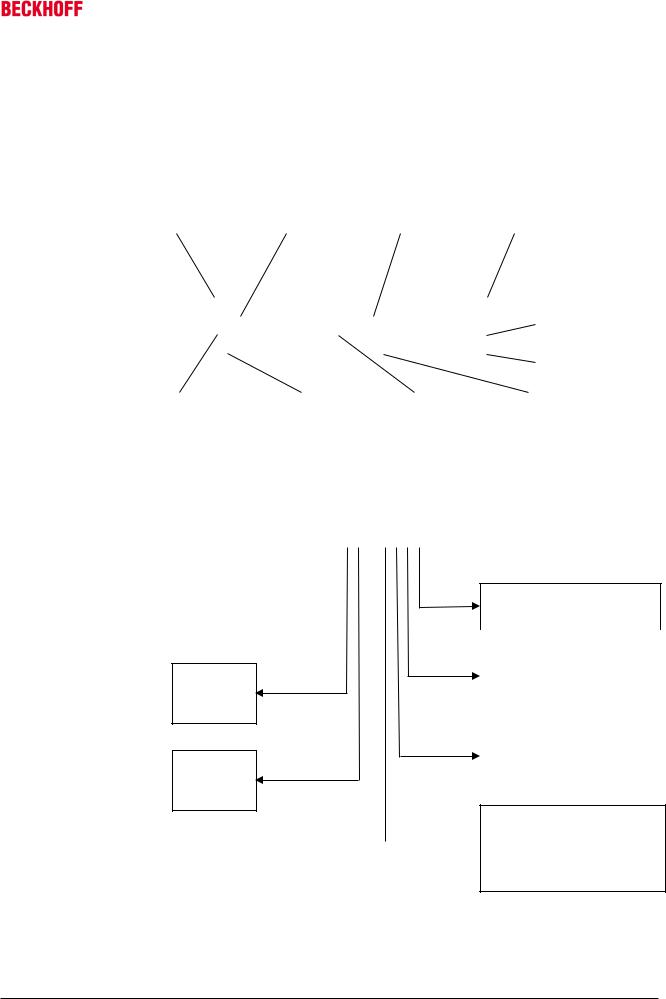
5.3AM3000 type key
AM30 6 2 – 0 P 0 1 – 0000
|
|
|
|
|
|
|
|
|
|
|
|
|
|
|
Flange size |
|
|
|
|
|
|
|
|
|
|
|
Connection |
||
1 |
= 40 mm |
|
|
|
|
|
|
|
|
|
|
0 |
rotatable angular connectors |
|
2 |
= 58 mm |
|
|
|
|
|
|
|
|
|
|
1 |
0.5 m cable with connector |
|
|
|
|
|
|
|
|
|
|
|
|
||||
3 |
= 70 mm |
|
|
|
|
|
|
|
|
|
|
5 |
yTec connector |
|
4 |
= 84 mm |
|
|
|
|
|
|
|
|
|
|
6 |
terminal box |
|
|
|
|
|
|
|
|
||||||||
5 |
= 108 mm |
|
|
|
|
|
|
|
|
|
|
|
|
|
|
|
|
|
|
|
|
|
|
|
|
|
|
||
6 |
= 138 mm |
|
|
|
|
|
|
|
|
|
|
|
|
|
|
|
|
|
|
|
|
|
|
|
|
Brake |
|||
7 |
= 188 mm |
|
|
|
|
|
|
|
|
|
|
|
||
8 |
= 250 mm |
|
|
|
|
|
|
|
|
|
|
0 |
none brake |
|
|
|
|
|
|
|
|
|
|
||||||
|
|
|
|
|
|
|
|
|
|
|
1 |
24 V holding brake |
||
|
|
|||||||||||||
Rotor length |
|
|
|
|
|
|
|
|
|
|
|
|
|
|
|
|
|
|
|
|
|
|
|
|
|
Feedback unit |
|||
1 |
|
|
|
|
|
|
|
|
|
|
|
|
||
2 |
|
|
|
|
|
|
|
|
|
|
|
|
0 |
resolver, 2-pole |
3 |
|
|
|
|
|
|
|
|
|
|
|
|
1 |
EnDAT single turn |
|
|
|
|
|
|
|
|
|
|
|
|
|||
4 |
|
|
|
|
|
|
|
|
|
|
|
|
2 |
EnDAT multi turn |
|
|
|
|
|
|
|
|
|
|
|
|
3 |
BISS single turn |
|
5 |
|
|
|
|
|
|
|
|
|
|
|
|
||
|
|
|
|
|
|
|
|
|
|
|
|
|
4 |
BISS multi turn |
|
|
|
|
|
|
|
|
|
|
|
|
|
5 |
EQI single turn |
|
|
|
|
|
|
|
|
|
|
|
|
|
6 |
EQI multi turn |
|
|
|
|
|
|
|
|
|
|
|
|
|
7 |
SKS single turn |
|
|
|
|
|
|
|
|
|
|
|
|
|
8 |
SKM multi turn |
|
|
|
|
|
|
|
|
|
|
|
|
|
|
|
|
|
|
|
|
|
|
|
|
|
|
|
|
|
|
|
|
|
|
|
|
|
|
|
|
|
|
|
Winding type |
|
|
|
|
|
|
|
|
|
|
|
|
|
|
A…Z |
|
|
|
|
|
|
|
|
|
|
|
|
|
|
||
|
|
|
|
|
|
|
|
|
|
|
|
|
S = special winding |
|
|
|
|
|
|
|
|
|
|
|
|
|
|
|
|
|
|
|
|
|
|
|
|
|
|
|
|
|
|
|
|
|
|
|
|
|
|
|
|
|
|
|
|
Shaft |
|
|
|
|
|
|
|
|
|
|
|
|
|
|
0 |
smooth shaft |
|
|
|
|
|
|
|
|
|
|
|
|
|
1 |
feather key groove |
|
|
|
|
|
|
|
|
|
|
|
|
|
2 |
sealing ring – smooth shaft |
|
|
|
|
|
|
|
|
|
|
|
|
|
3 |
sealing ring – feather key groove |
|
|
|
|
|
|
|
|
|
|
|
|
|
5 |
food industry |
|
|
|
|
|
|
|
|
|
|
|
|
|
|
|
14 |
Version: 1.5 |
AM3000 / AM3500 |
Drive Technology |
5 Product identification |
5.4AM3500, scope of supply
Please check that the delivery includes the following items:
•Motor from the AM3500 series
•Motor package leaflet (short info)
5.5AM3500 nameplate
Servomotor type |
|
Serial number |
|
Item number |
|
Date of manufacture |
|
|
|
|
|
|
|
BECKHOFF |
|
|
|
|
|
|
|
|
|
|
|
||||
|
|
|
|
|
|
|
|
|
|
|
|
|
|
|
|
Type |
|
|
|
|
|
|
|
|
|
|
|
|
|
|
|
SN |
|
|
|
|
Art.No. |
|
|
|
|
|
|
|
|
Insulation class |
|
Mo |
|
|
Nm |
Udc |
|
|
V |
Iso. cl. |
|
|
|
|
|
|
|
|
|
|
|
|
|
|
|
|
|
||||||
Nn |
|
r/min |
In |
|
|
A |
IP |
|
|
|
|
|
|
||
|
|
|
|
|
|
|
Protection class |
||||||||
Made in EU |
|
|
|
|
|
|
|
|
|
|
|
|
|
|
|
|
|
|
|
|
|
|
|
|
|
|
|
|
|
||
|
|
|
|
|
|
|
|
|
|
|
|||||
Standstill torque |
|
|
Nominal speed |
|
DC link voltage |
|
|
Rated current |
|
||||||
|
|
|
|
|
|
|
|
|
|
|
|
|
|
|
|
5.6AM3500 type key
Flange size
4 84 mm
5 108 mm
6 138 mm
Rotor length
1
2
3
AM35 4 1 – 0 0 0 1
Brake
0 |
without brake |
1 |
24V holding brake |
|
|
Feedback unit |
|
0 |
Resolver |
3 |
BiSS single turn |
4 |
BISS multi turn |
|
|
Winding type |
|
0 |
3000 min-1 |
1 |
6000 min-1 |
9 |
special winding |
|
|
Shaft
0 smooth shaft  1 feather key groove
2 sealing ring – smooth shaft
3 sealing ring – feather key groove
AM3000 / AM3500 |
Version: 1.5 |
15 |

6 Technical description |
Drive Technology |
6 Technical description
6.1Design of the motors
The synchronous servomotors of the AM3000 and AM3500 series are brushless three-phase motors for demanding servo-applications. In conjunction with our digital servo drives they are particularly suitable for positioning tasks in industrial robots, machine tools, transfer lines etc. with demanding requirements in terms of dynamics and stability.
The servomotors are equipped with permanent magnets in the rotor. This advanced neodymium magnetic material makes a significant contribution to the motors' exceptional dynamic properties. A three-phase winding is housed in the stator, and this is powered by the servo drive. The motor has no brushes, the commutation being implemented electronically in the servo drive.
The temperature of the winding is monitored by temperature sensors in the stator windings and is signalled via an electrically isolated thermistor (PTC, _550 Ω / _1330 Ω).
The motors normally have an integrated resolver to provide feedback. Beckhoff servo drives analyse the resolver position of the rotor and supply the motors with sine currents. The optional feedback systems may require modification of the motor length and cannot be retrofitted.
The motors are available with or without built-in holding brake. The brake cannot be retrofitted.
The motors have a matt black coating (RAL 9005). The finish is not resistant against solvents (e.g. trichlorethylene, thinners or similar). The “Washdown”-model is white coated and FDA (Food and Drug Administration) conform.
6.2General technical data
Climate category |
3K3 according to EN 50178 |
|
|
|
|
Ambient temperature |
+5 - +40 °C for site altitudes up to 1000 m amsl |
|
(at rated values) |
It is vital to consult our applications department for ambient temperatures |
|
above 40 °C and encapsulated installation of the motors. |
||
|
||
Permissible humidity |
95% relative humidity, non-condensing |
|
(at rated values) |
|
|
|
|
|
Power derating |
For site altitudes above 1000 m amsl and 40 °C |
|
(currents and torques) |
6% at 2000 m amsl |
|
17% at 3000m amsl |
||
|
||
|
30% at 4000m amsl |
|
|
55% at 5000m amsl |
|
|
No derating for site altitudes above 1000 m amsl with temperature |
|
|
reduction of 10K / 1000m |
|
Ball bearing service life |
=20,000 operating hours |
|
|
|
|
Technical data |
→ see Section 10 |
|
|
|
|
Storage and transport data |
→ see Section 4 |
|
|
|
16 |
Version: 1.5 |
AM3000 / AM3500 |
Drive Technology |
6 Technical description |
6.3Standard features
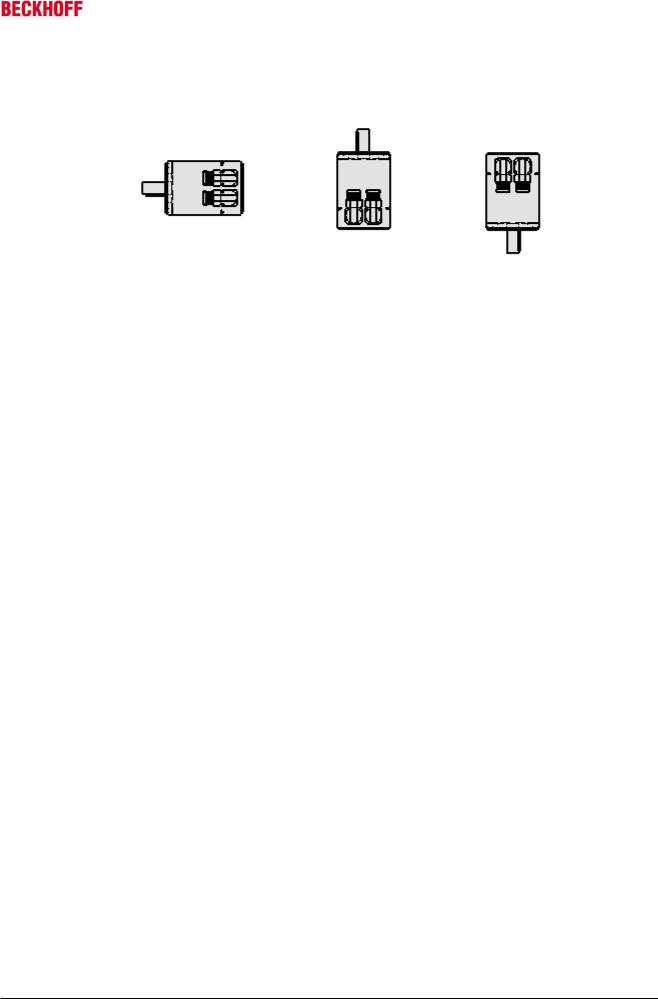
6.3.1Style
The basic style for the AM3000 and AM3500 synchronous servomotors is IM B5 according to DIN EN 60034-7.
IM B 5 (B5) |
IM V 3 (V3) |
IM V 1 (V) |
The permitted mounting positions are specified in the technical data.
6.3.2Shaft end, A-side
Power transmission is made through the cylindrical shaft end A, fit k6 (AKM1: h7) according to EN 50347, with a locking thread or optionally with a feather key groove. The bearings are designed for a service life of 20,000 hours.
Radial force
If the motors drive via pinions or toothed belts, then high radial forces will occur. The permissible values at the shaft end, depending on the speed, may be read from the diagrams in the Section 10. The permissible maximum values can be found in the technical data. Power take-off from the middle of the free end of the shaft allows a 10% increase in FR.
Axial force
Axial forces arise when assembling pinions or pulleys on the shaft and using angular gearheads, for example. The permissible maximum values can be found in the technical data.
Coupling
Double-coned collets, possibly in association with metal bellows couplings, have proven themselves as excellent, zero backlash coupling elements.
6.3.3Flange
Flange dimensions according to IEC standard, fit j6 (AM301x: h7), accuracy according to DIN 42955 Tolerance class: N
6.3.4 |
Protection class |
|
Standard version |
IP65 |
|
Standard shaft bushing |
IP54 |
|
Shaft bushing with shaft sealing ring |
IP67 |
|
6.3.5Overtemperature protection
The standard version of each motor is fitted with an electrically isolated PTC with a rated temperature of 155 °C
± 5%. The PTC does not provide any protection against short, heavy overloading.
Provided that our preassembled cable is used, the PTC is integrated into the monitoring system of the digital servo drives.
6.3.6Insulation material class
The motors conform to insulation material class F according to IEC 60085 (UL 1446 class F).
AM3000 / AM3500 |
Version: 1.5 |
17 |
6 Technical description |
Drive Technology |
6.3.7Vibration class
The motors are made to vibration class A according to DIN EN 60034-14. For a speed range of 600-3600 rpm and a shaft centre height between 56-132 mm, this means that the actual value of the permitted vibration severity is 1.6 mm/s.
Speed [rpm] |
Max. rel. vibration |
Max. run-out [µm] |
|
displacement [µm] |
|
<= 1800 |
90 |
23 |
> 1800 |
65 |
16 |
6.3.8Connection technology
The motors are fitted with angular connectors (AM301x: straight connectors at the cable ends) for the power supply and the feedback signals.
The mating connectors are not included in the scope of supply. We can supply preassembled feedback and power cables. Information regarding the cable materials can be found in Section 8.2.
6.3.9Feedback unit
Standard |
|
Resolver |
Two-pole, hollow shaft |
|
|
|
|
|
|
Option |
|
EnDAT Encoder, Singleturn |
AM302x-AM304x: ECN 1113, |
|
|
|
|
AM305x-AM307x: EQN 1325 |
|
Option |
|
EnDAT Encoder, Multiturn |
AM302x-AM304x: EQN 1125 |
|
|
|
|
AM305x-AM307x: EQN 1325 |
|
Option |
|
BiSS Encoder, Single- / Multiturn |
AM302x-AM304x: AD36 |
|
|
|
|
AM305x-AM307x: AD58 |
|
Option |
|
BiSS Encoder, Single- / Multiturn |
AM35xx: AD34 |
|
|
|
|
|
|
|
|
|
|
|
|
Motor length |
|
|
|
|
The motor length depends on the built-in feedback unit, among other factors. Retrofitting is not |
|
||
Note |
possible. |
|
|
|
6.3.10 Holding brake
Serious risk of injury!
The holding brake is not personal safety. If the brake is released then the rotor can be moved WARNING without a remanent torque!
The AM302x-AM308x and AM35xx motors are optionally available with an in-built holding brake. The AM3000 model features a spring-actuated brake (24 V DC), the AM3500 features a permanent-magnet brake (24 V DC). When the brake is de-energised it blocks the rotor. The holding brakes are designed as standstill brakes and are not suited for repeated operational braking.
The holding brakes can be controlled directly by the servo drive (no personal safety!), in which case the brake winding is suppressed in the servo drive. Additional circuitry is not required.
If the holding brake is not controlled directly by the servo drive, additional circuitry (e.g. varistor) is required. Consult our applications department beforehand.
|
Motor length |
|
The motor length depends on the built-in holding brake, among other factors. It is not possible to |
Note |
fit one at a later date. |
18 |
Version: 1.5 |
AM3000 / AM3500 |

|
|
Drive Technology |
|
|
|
6 Technical description |
|||
6.3.11 |
Pole numbers |
|
|
|
|
|
|
||
|
|
|
|
|
|
|
|
|
|
Motor |
|
Poles |
Motor |
Poles |
Motor |
Poles |
Motor |
Poles |
|
AM301x |
|
6 |
AM304x |
10 |
AM307x |
10 |
AM354x |
10 |
|
AM302x |
|
6 |
AM305x |
10 |
AM308x |
10 |
AM355x |
10 |
|
AM303x |
|
8 |
AM306x |
10 |
|
|
AM356x |
10 |
|
6.4Options
Holding brake
The holding brake is integrated in the motor. It increases the motor length.
Radial shaft-sealing ring
Radial shaft-sealing ring (Teflon) for sealing against oil mist and oil spray. This increases the protection class of the shaft bushing to IP67.
Feather key
The motors are available with feather key groove and fitted feather key according to DIN6885. The rotor is balanced with half a feather key.
EnDat (only AM30xx), BiSS
This model features a different feedback system in place of the resolver, which may result in an increase of the motor length.
Installation options and reduction of rated values
With the exception of the sealing ring, the options cannot be retrofitted.
Note Options such as sealing ring, holding brake, EnDAT or BiSS can lead to a reduction of the rated data.
6.5Selection criteria
The three-phase servomotors are designed for operation with servo drives.
Both units together form a speed or torque control loop.
The main selection criteria are:
— |
Standstill torque |
M0 [Nm] |
— Rated speed at rated supply voltage |
nn [min-1] |
|
— Moment of inertia of motor and load |
J [kgcm²] |
|
— |
Effective torque (calculated) |
Mrms [Nm] |
The static load and the dynamic load (acceleration/braking) must be taken into account in the calculation of the required motors and servo drives. Formulas and calculation example are available from our applications department on request.
AM3000 / AM3500 |
Version: 1.5 |
19 |

7 Mechanical installation |
Drive Technology |
7 Mechanical installation
7.1Important notes
Destruction of the motors
•Protect the motors from unacceptable stresses. Take care, especially during transport and
Attention |
handling, that components are not bent and that insulation clearances are not altered. |
•The site must be free of conductive and aggressive material. For V3-mounting (shaft end upwards), make sure that no liquids can enter the bearings. If an encapsulated assembly is required, please consult our applications department beforehand.
•Ensure unhindered ventilation of the motors and observe the permissible ambient and flange temperatures. For ambient temperatures above 40 °C please consult our applications department beforehand.
•Servomotors are precision devices. The flange and shaft are especially vulnerable during storage and assembly. It is important to use the locking thread which is provided to tighten up couplings, gear wheels or pulleys and warm up the drive components, where possible. Blows or the use of force will lead to damage to the ball bearings and the shaft.
•Wherever possible, use only backlash-free, frictionally-locking collets or couplings. Ensure correct alignment of the couplings. A displacement will cause unacceptable vibration and the destruction of the ball bearings and the coupling.
•For toothed belts, it is vital to observe the permissible radial forces. An excessive radial load on the shaft will significantly shorten the life of the motor.
•Avoid axial loads on the motor shaft, as far as possible. Axial loading significantly shortens the life of the motor.
•In any case, avoid creating a mechanically constrained motor shaft mounting by using a rigid coupling with additional external bearings (e.g. in a gearbox).
•Take note of the no. of motor poles and the no. of resolver poles and ensure that the correct setting is made in the used servo drives. An incorrect setting can lead to the destruction of the motor, especially with small motors.
•Check compliance the permitted radial and axial loads FR and FA. When using a toothed belt drive, the minimum permitted diameter of the pinion follows from the equation: d min ≥ MFR0 x2
20 |
Version: 1.5 |
AM3000 / AM3500 |
Loading...