BECKHOFF AX5000 S-IDN User Manual
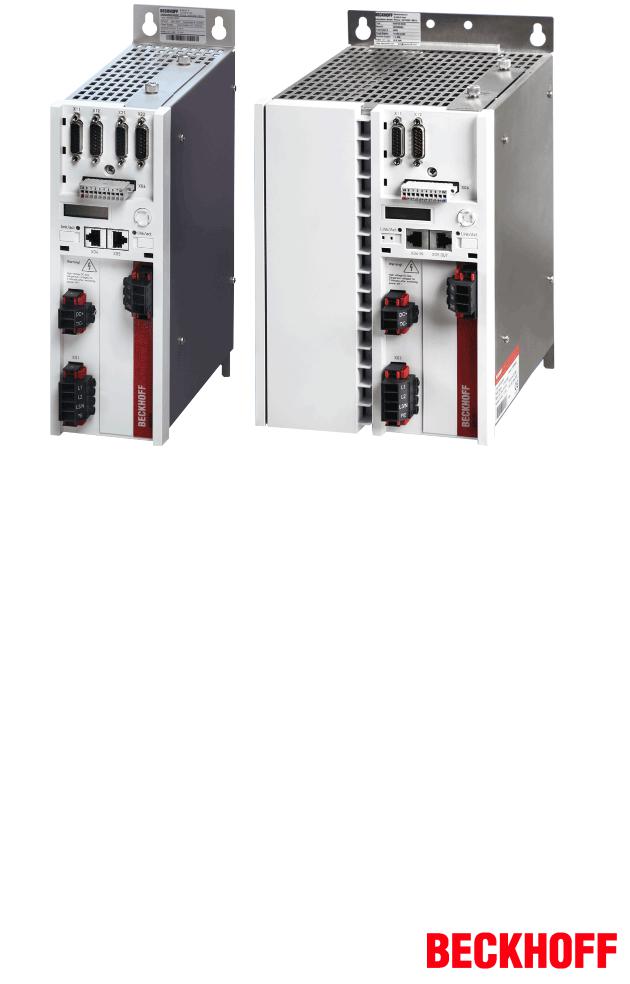
AX5000 IDNDescriptions
(SIDN's)
Version 3.1
Date 20150414

|
|
|
Table of Contents |
Table of Contents |
|
|
|
1 |
Preface........................................................................................................................................................ |
|
7 |
|
1.1 Notes on the documentation............................................................................................................. |
|
7 |
|
1.2 Safety instructions ............................................................................................................................ |
|
8 |
2 |
SIDNs......................................................................................................................................................... |
|
9 |
|
S00001 Control unit cycle time (TNcyc) ......................................................................................... |
9 |
|
|
S00002 Communication cycle time (tScyc).................................................................................. |
10 |
|
|
S00007 Feedback acquisition capture point (t4) .......................................................................... |
11 |
|
|
S00011 Class 1 diagnostic (C1D) ................................................................................................ |
|
12 |
|
S00012 Class 2 diagnostic (C2D) ................................................................................................ |
|
14 |
|
S00013 Class 3 diagnostic (C3D) ................................................................................................ |
|
16 |
|
S00015 Telegram type ................................................................................................................. |
|
17 |
|
S00016 Configuration list of AT.................................................................................................... |
|
18 |
|
S00017 IDNlist of all operation data............................................................................................ |
|
19 |
|
S00018 IDNlist of operation data for CP2 (PreOp) .................................................................... |
20 |
|
|
S00019 IDNlist of operation data for CP3 (SafeOp) ................................................................... |
21 |
|
|
S00020 IDNlist of operation data for CP4 (Op) .......................................................................... |
22 |
|
|
S00021 IDNlist of invalid operation data for CP2 (PreOp) .......................................................... |
23 |
|
|
S00022 IDNlist of invalid operation data for CP3 (SafeOp) ........................................................ |
25 |
|
|
S00024 Configuration list of MDT ................................................................................................ |
|
27 |
|
S00025 IDNlist of all procedure commands................................................................................ |
29 |
|
|
S00029 MDT error counter........................................................................................................... |
|
30 |
|
S00030 Manufacturer version ...................................................................................................... |
|
31 |
|
S00031 Hardware version............................................................................................................ |
|
33 |
|
S00032 Primary operation mode.................................................................................................. |
|
35 |
|
S00033 Secondary operation mode 1.......................................................................................... |
|
37 |
|
S00034 Secondary operation mode 2.......................................................................................... |
|
39 |
|
S00035 Secondary operation mode 3.......................................................................................... |
|
41 |
|
S00036 Velocity command value ................................................................................................. |
|
43 |
|
S00037 Additive velocity command value.................................................................................... |
44 |
|
|
S00040 Velocity feedback value 1 ............................................................................................... |
|
45 |
|
S00043 Velocity polarity parameter ............................................................................................. |
|
46 |
|
S00044 Velocity data scaling type ............................................................................................... |
|
47 |
|
S00045 Velocity data scaling factor ............................................................................................. |
|
48 |
|
S00046 Velocity data scaling exponent ....................................................................................... |
49 |
|
|
S00047 Position command value................................................................................................. |
|
50 |
|
S00048 Additive position command value ................................................................................... |
51 |
|
|
S00051 Position feedback value 1 (motor feedback)................................................................... |
52 |
|
|
S00053 Position feedback value 2 (external feedback) ............................................................... |
53 |
|
|
S00055 Position polarity parameters ........................................................................................... |
|
54 |
|
S00076 Position data scaling type ............................................................................................... |
|
55 |
|
S00079 Position resolution........................................................................................................... |
|
57 |
|
S00080 Torque command value .................................................................................................. |
|
58 |
|
S00081 Additive torque command value...................................................................................... |
59 |
|
|
Sx0082 Positive torque limit value ............................................................................................... |
|
60 |
AX5000 IDNDescriptions |
Version 3.1 |
3 |
|

Table of Contents |
|
|
|
Sx0083 Negative torque limit value.............................................................................................. |
62 |
|
S00084 Torque feedback value ................................................................................................... |
64 |
|
S00085 Torque polarity parameter............................................................................................... |
65 |
|
S00086 Torque/force data scaling type........................................................................................ |
66 |
|
Sx0091 Bipolar velocity limit value ............................................................................................... |
67 |
|
Sx0092 Bipolar torque limit value................................................................................................. |
69 |
|
S00095 Diagnostic message........................................................................................................ |
71 |
|
S00099 Reset class 1 diagnostic (pc) .......................................................................................... |
73 |
|
S00100 Velocity loop proportional gain........................................................................................ |
74 |
|
S00101 Velocity loop integral action time .................................................................................... |
75 |
|
S00103 Modulo Value .................................................................................................................. |
76 |
|
S00104 Position loop Kvfactor .................................................................................................... |
77 |
|
S00106 Current loop proportional gain 1 ..................................................................................... |
78 |
|
S00107 Current control loop integral action time 1 ...................................................................... |
79 |
|
Sx0109 Motor peak current .......................................................................................................... |
80 |
|
S00110 Amplifier peak current ..................................................................................................... |
82 |
|
Sx0111 Motor continuous stall current ......................................................................................... |
89 |
|
S00112 Amplifier rated current..................................................................................................... |
91 |
|
Sx0113 Maximum motor speed.................................................................................................... |
98 |
|
S00119 Current loop proportional gain 2 ................................................................................... |
100 |
|
S00120 Current control loop integral action time 2 .................................................................... |
101 |
|
S00124 Standstill window .......................................................................................................... |
102 |
|
S00126 Torque threshold Tx...................................................................................................... |
103 |
|
S00130 Probe value 1 positive edge.......................................................................................... |
104 |
|
S00131 Probe value 1 negative edge ........................................................................................ |
105 |
|
S00134 Master control word ...................................................................................................... |
106 |
|
S00135 Drive status word .......................................................................................................... |
108 |
|
Sx0136 Positive acceleration limit value .................................................................................... |
110 |
|
Sx0137 Negative acceleration limit value................................................................................... |
112 |
|
S00143 Sercos interface version ............................................................................................... |
114 |
|
S00149 Positive drive stop procedure command (pc)................................................................ |
115 |
|
S00156 Velocity feedback value 2 (external feedback) ............................................................. |
116 |
|
S00159 Monitoring window ....................................................................................................... |
117 |
|
S00160 Acceleration data scaling type ...................................................................................... |
118 |
|
S00161 Acceleration data scaling factor .................................................................................... |
119 |
|
S00162 Acceleration data scaling exponent .............................................................................. |
120 |
|
S00163 Weight counterbalance ................................................................................................. |
121 |
|
S00169 Probe control parameter ............................................................................................... |
122 |
|
S00170 Probing cycle procedure command (pc) ....................................................................... |
124 |
|
S00179 Probe status.................................................................................................................. |
125 |
|
S00185 Length of the configurable data record in the AT.......................................................... |
126 |
|
S00186 Length of the configurable data record in the MDT....................................................... |
127 |
|
S00187 IDNlist of configurable data in the AT .......................................................................... |
128 |
|
S00188 IDNlist of configurable data in the MDT ....................................................................... |
130 |
|
S00189 Following distance ........................................................................................................ |
131 |
|
Sx0196 Motor rated current........................................................................................................ |
132 |
4 |
Version 3.1 |
AX5000 IDNDescriptions |

|
|
Table of Contents |
S00200 Amplifier warning temperature ...................................................................................... |
134 |
|
S00201 Motor warning temperature........................................................................................... |
|
135 |
S00203 Amplifier shut down temperature .................................................................................. |
136 |
|
S00204 Motor shut down temperature ....................................................................................... |
137 |
|
S00206 Drive on delay time ....................................................................................................... |
|
138 |
S00207 Drive off delay time ....................................................................................................... |
|
139 |
S00216 Switch parameter set (pc) ............................................................................................. |
|
140 |
S00217 Parameter set preselection ........................................................................................... |
|
141 |
S00219 IDNlist of parameter set ............................................................................................... |
|
142 |
S00254 Actual parameter set..................................................................................................... |
|
143 |
S00256 Multiplication factor 1 (motor feedback) ....................................................................... |
144 |
|
S00257 Multiplication factor 2 (external feedback) .................................................................... |
145 |
|
S00267 Password ...................................................................................................................... |
|
146 |
S00273 Maximum drive off delay time ....................................................................................... |
148 |
|
S00274 Received drive addresses............................................................................................. |
|
149 |
S00292 List of supported operation modes................................................................................ |
150 |
|
S00295 Drive enable delay time ................................................................................................ |
|
152 |
S00296 Velocity feed forward gain............................................................................................. |
|
153 |
S00301 Allocation of realtime control bit 1................................................................................ |
154 |
|
S00303 Allocation of realtime control bit 2................................................................................ |
155 |
|
S00305 Allocation of realtime status bit 1 ................................................................................. |
156 |
|
S00307 Allocation of realtime status bit 2 ................................................................................. |
157 |
|
S00347 Velocity error................................................................................................................. |
|
158 |
S00348 Acceleration feed forward gain ..................................................................................... |
159 |
|
Sx0372 Drive Halt acceleration bipolar ...................................................................................... |
161 |
|
S00374 Procedure command error list....................................................................................... |
163 |
|
S00375 Diagnostic numbers list................................................................................................. |
|
165 |
S00380 DC bus voltage ............................................................................................................. |
|
167 |
S00381 DC bus current.............................................................................................................. |
|
168 |
S00383 Motor temperature ........................................................................................................ |
|
169 |
S00384 Amplifier temperature.................................................................................................... |
|
170 |
S00390 Diagnostic number ........................................................................................................ |
|
171 |
S00403 Position feedback value status ..................................................................................... |
172 |
|
S00405 Probe 1 enable.............................................................................................................. |
|
173 |
S00409 Probe 1 positive latched (Counter) ............................................................................... |
174 |
|
S00410 Probe 1 negative latched (Counter) .............................................................................. |
176 |
|
Sx0429 Emergency stop deceleration........................................................................................ |
|
178 |
S00432 Serial number drive control ........................................................................................... |
|
180 |
S00435 Operating time drive control.......................................................................................... |
|
181 |
S00436 Operating time power stage.......................................................................................... |
|
182 |
S00903 Configuration list of dynamic AT ................................................................................... |
183 |
|
S00904 Configuration list of dynamic MDT ................................................................................ |
184 |
|
S00905 IDNlist of configurable data in the dynamic AT............................................................ |
185 |
|
S00906 IDNlist of configurable data in the dynamic MDT......................................................... |
186 |
|
S00907 Control word dynamic MDT .......................................................................................... |
|
187 |
S00908 Status word dynamic AT ............................................................................................... |
|
188 |
AX5000 IDNDescriptions |
Version 3.1 |
5 |

Table of Contents |
|
S00909 Dynamic MDT error counter.......................................................................................... |
189 |
3 Support and Service.............................................................................................................................. |
190 |
6 |
Version 3.1 |
AX5000 IDNDescriptions |

Preface
1 Preface
1.1Notes on the documentation
This description is only intended for the use of trained specialists in control and automation engineering who are familiar with the applicable national standards.
It is essential that the following notes and explanations are followed when installing and commissioning these components.
The responsible staff must ensure that the application or use of the products described satisfy all the requirements for safety, including all the relevant laws, regulations, guidelines and standards.
Disclaimer
The documentation has been prepared with care. The products described are, however, constantly under development.
For that reason the documentation is not in every case checked for consistency with performance data, standards or other characteristics.
In the event that it contains technical or editorial errors, we retain the right to make alterations at any time and without warning.
No claims for the modification of products that have already been supplied may be made on the basis of the data, diagrams and descriptions in this documentation.
Trademarks
Beckhoff®, TwinCAT®, EtherCAT®, Safety over EtherCAT®, TwinSAFE®, XFC®and XTS® are registered trademarks of and licensed by Beckhoff Automation GmbH.
Other designations used in this publication may be trademarks whose use by third parties for their own purposes could violate the rights of the owners.
Patent Pending
The EtherCAT Technology is covered, including but not limited to the following patent applications and patents:
EP1590927, EP1789857, DE102004044764, DE102007017835
with corresponding applications or registrations in various other countries.
The TwinCAT Technology is covered, including but not limited to the following patent applications and patents:
EP0851348, US6167425 with corresponding applications or registrations in various other countries.
EtherCAT® is registered trademark and patented technology, licensed by Beckhoff Automation GmbH, Germany
Copyright
© Beckhoff Automation GmbH & Co. KG, Germany.
The reproduction, distribution and utilization of this document as well as the communication of its contents to others without express authorization are prohibited.
Offenders will be held liable for the payment of damages. All rights reserved in the event of the grant of a patent, utility model or design.
AX5000 IDNDescriptions |
Version 3.1 |
7 |
Preface
1.2Safety instructions
Safety regulations
Please note the following safety instructions and explanations!
Productspecific safety instructions can be found on following pages or in the areas mounting, wiring, commissioning etc.
Exclusion of liability
All the components are supplied in particular hardware and software configurations appropriate for the application. Modifications to hardware or software configurations other than those described in the documentation are not permitted, and nullify the liability of Beckhoff Automation GmbH & Co. KG.
Personnel qualification
This description is only intended for trained specialists in control, automation and drive engineering who are familiar with the applicable national standards.
Description of symbols
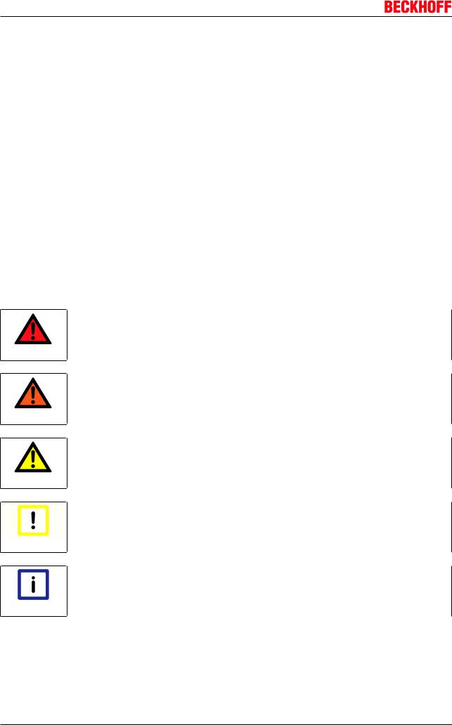
In this documentation the following symbols are used with an accompanying safety instruction or note. The safety instructions must be read carefully and followed without fail!
Serious risk of injury!
Failure to follow the safety instructions associated with this symbol directly endangers the life and health of persons.
DANGER
Risk of injury!
Failure to follow the safety instructions associated with this symbol endangers the life and health of persons.
WARNING
Personal injuries!
Failure to follow the safety instructions associated with this symbol can lead to injuries to persons.
CAUTION
Damage to the environment or devices
Failure to follow the instructions associated with this symbol can lead to damage to the en vironment or equipment.
Attention
Tip or pointer
This symbol indicates information that contributes to better understanding.
Note
8 |
Version 3.1 |
AX5000 IDNDescriptions |

SIDNs
2 SIDNs
S00001 Control unit cycle time (TNcyc)
The parameter contains information regarding the time intervals at which the numeric control makes new set values available.
Attributes
Name |
Value |
Format |
UDEC |
Data length |
16 |
Decimal point |
0 |
Min value |
125 |
Max value |
20 000 |
Default value |
500 |
Unit |
µs |
Changeable in EtherCAT state |
PreOp |
Cyclic transfer |
No |
Device parameter |
Yes |
Related to interface revision |
from 200: Interpolation P00556 |
This parameter must be transferred in PreOp from the master to the slave and is taken into account in the slave from SafeOp. S00001 must be equal to S00002.
When using a control mode which contains position control, S00001 must be equal or greater than P00004. If S00001 is longer than P00004, AX5000 interpolates the missing set values. Interpolation can be configured in P00556.
IDNs involved
S 0 0001 [} 9], S 0 0002 [} 10], P00004, P00556
Note
AX5000 IDNDescriptions |
Version 3.1 |
9 |

SIDNs
S00002 Communication cycle time (tScyc)
The parameter contains information regarding the time intervals at which the fieldbus (EtherCAT) transfers the cyclic data of the master data telegram (MDT) and the drive telegram (AT).
Attributes
Name |
Value |
Format |
UDEC |
Data length |
16 |
Decimal point |
0 |
Min value |
125 |
Max value |
20 000 |
Default value |
500 |
Unit |
µs |
Changeable in EtherCAT state |
PreOp |
Cyclic transfer |
No |
Device parameter |
Yes |
Related to interface revision |
No |
This parameter must be transferred in PreOp from the master to the slave and is active in the slave from SafeOp. This parameter is defined as 125 μs, 250 μs etc. up to 20000 μs, in increments of 250 μs. Values permitted in S00002 depend on the position controller cycle.
10 |
Version 3.1 |
AX5000 IDNDescriptions |
SIDNs
S00007 Feedback acquisition capture point (t4)
The time of measurement of the actual values is synchronised by the drive with the synchronisation signal Sync 1 of the EtherCAT distributed clock (DC).
Attributes
Name |
Value |
Format |
UDEC |
Data length |
16 |
Decimal point |
0 |
Min value |
0 |
Max value |
0 |
Default value |
0 |
Unit |
µs |
Changeable in EtherCAT state |
PreOp |
Cyclic transfer |
No |
Device parameter |
No |
Related to interface revision |
No |
In this way the master can specify the same actual value measuring time for all drives that operate in a coordinated way. This ensures synchronisation of the actual value acquisition for the respective drives. From SafeOp, the drive activates the measuring time for the actual values.
IDNs involved
S 0 0002 [} 10]
Note
AX5000 IDNDescriptions |
Version 3.1 |
11 |
SIDNs
S00011 Class 1 diagnostic (C1D)
The parameter contains error groups that trigger a "drive shut down" error.
Attributes
Name |
Value |
Format |
Binary |
Data length |
16 |
Decimal point |
0 |
Min value |
|
Max value |
|
Default value |
|
Unit |
|
Changeable in EtherCAT state |
No |
Cyclic transfer |
AT |
Device parameter |
No |
Related to interface revision |
No |
If an error is diagnosed in the drive, this results in an error response and the error bit is set, as described below. In addition, error bit 13 is set by S00135 to "1" and is only reset to "0" by the drive when the drive has executed the command S00099 and any errors have been cleared.
To precisely identify the error, read the error memory.
Bit pattern:
Bit Meaning
0Overload shut down
Overload shut down
0= no error
1= error
1Amplifier overtemperature shut down
Amplifier overtemperature shut down
0= no error
1= error
2Motor overtemperature shut down
Motor overtemperature shut down
0= no error
1= error
3Cooling error shut down
Cooling error shut down
0= no error
1= error
4Control voltage error
Control voltage error
0= no error
1= error
5Feedback error
Feedback error
0= no error
1= error
12 |
Version 3.1 |
AX5000 IDNDescriptions |
SIDNs
Bit Meaning
6Commutation error
Commutation error
0= no error
1= error
7Overcurrent error
Overcurrent error
0= no error
1= error
8Overvoltage error
Overvoltage error
0= no error
1= error
9Undervoltage error
Undervoltage error
0= no error
1= error
10Power supply phase error
Power supply phase error
0= no error
1= error
11Excessive position deviation
Excessive position deviation
0= no error
1= error
12Communication error bit
Communication error bit
0= no error
1= error
13Overtravel limit exceeded
Overtravel limit exceeded (shut down)
0= no error
1= error
14Reserved
15Manufacturer specific error
Manufacturer specific error
0= no error
1= error
IDN P00350 Error reaction check word
With this IDN you can parameterise a general reaction to an error and/or influence the be haviour of the two axes in the case of a 2channel AX5000.
Note
IDNs involved
S 0 0135 [} 108], S 0 0099 [} 73], P00350
Note
AX5000 IDNDescriptions |
Version 3.1 |
13 |
SIDNs
S00012 Class 2 diagnostic (C2D)
The parameter contains warning groups that trigger a drive warning.
Attributes
Name |
Value |
Format |
Binary |
Data length |
16 |
Decimal point |
0 |
Min value |
|
Max value |
|
Default value |
|
Unit |
|
Changeable in EtherCAT state |
No |
Cyclic transfer |
AT |
Device parameter |
No |
Related to interface revision |
No |
If S00012 changes, the C2D bit in S00135 (bit 12) is set to "1". Once the changed status of S00012 has been read via mailbox, the change bit is reset to "0". In this parameter the bit is automatically reset, once the cause has been rectified.
To precisely identify the warning, read the error memory.
Bit pattern:
Bit Meaning
0Overload warning
Overload warning
0= no warning
1= warning
1Amplifier overtemperature warning
Amplifier overtemperature warning
0= no warning
1= warning
2Motor overtemperature warning
Motor overtemperature warning
0= no warning
1= warning
3Cooling error warning
Cooling error warning
0= no warning
1= warning
4Reserved
5Reserved
6Reserved
7Reserved
8Reserved
9Undervoltage warning (bus voltage)
Undervoltage warning (bus voltage)
0= no warning
1= warning
10 Reserved
14 |
Version 3.1 |
AX5000 IDNDescriptions |

SIDNs
Bit Meaning
11Reserved
12Reserved
13Reserved
14Reserved
15Manufacturerspecific warning
Manufacturerspecific warning
0 = no warning
1 = warning
IDNs involved
S 0 0135 [} 108]
Note
AX5000 IDNDescriptions |
Version 3.1 |
15 |
SIDNs
S00013 Class 3 diagnostic (C3D)
The parameter contains information groups that trigger a drive information.
Attributes
Name |
Value |
Format |
Binary |
Data length |
16 |
Decimal point |
0 |
Min value |
|
Max value |
|
Default value |
|
Unit |
|
Changeable in EtherCAT state |
No |
Cyclic transfer |
AT |
Device parameter |
No |
Related to interface revision |
No |
If an information is diagnosed in the drive, the change bit is set, as described below. In addition, change bit 11 is set by S00135 to "1" and is only reset again when the cause has been rectified and the parameter S00013 is read again.
In this parameter the bit is automatically reset, once the cause has been rectified.
Bit pattern:
Bit Meaning
0Reserved
1| n Feedback |< standstill window
This bit can be used to read the axis movement status.
0= no information
1= information
2Reserved
3|T| ≥ Tx
This bit can be used to read whether the currently applied force or torque is larger or smaller than the TX S00126 "Torque threshold".
0= no information
1= information
4 Reserved
15
IDNs involved
S 0 0135 [} 108]
Note
16 |
Version 3.1 |
AX5000 IDNDescriptions |
SIDNs
S00015 Telegram type
The parameter contains the information to indicate that the AX5000 supports the application telegram.
Attributes
Name |
Value |
Format |
Binary |
Data length |
16 |
Decimal point |
0 |
Min value |
|
Max value |
|
Default value |
7 |
Unit |
|
Changeable in EtherCAT state |
PreOp |
Cyclic transfer |
No |
Device parameter |
No |
Related to interface revision |
No |
If application telegram is selected, S00016 and S00024 can be configured freely.
Bit pattern:
Bits 02 |
MDT |
AT |
7 |
Application telegram |
Application telegram |
IDNs involved
S 0 0016 [} 18], S 0 0024 [} 27], S 0 0080 [} 58], S 0 0036 [} 43], S 0 0047 [} 50],
S 0 0040 [} 45], S 0 0051 [} 52], S 0 0053 [} 53]
Note
AX5000 IDNDescriptions |
Version 3.1 |
17 |
SIDNs
S00016 Configuration list of AT
The parameter contains the information to indicate which data are contained in the drive telegram (AT). Only data listed in S00187 are permitted as cyclic data in the drive telegram (AT).
Attributes
Name |
Value |
Format |
idn |
Data length |
416 |
Decimal point |
0 |
Min value |
|
Max value |
|
Default value |
|
Unit |
|
Changeable in EtherCAT state |
PreOp |
Cyclic transfer |
No |
Device parameter |
No |
Related to interface revision |
No |
Nested structure
Note the nesting depth and the structure information at the start of the descriptions.
Note
IDNs involved
S 0 0015 [} 17], S 0 0187 [} 128]
Note
Actual length
S00016Configuration list of AT / Actual length
Format |
Size in bit |
Offset |
Properties |
UINT |
16 |
0 |
|
Max length
S00016Configuration list of AT / Max length
Format |
Size in bit |
Offset |
Properties |
UINT |
16 |
16 |
|
Configured AT IDNs
S00016Configuration list of AT / Configured AT IDNs
Format |
Size in bit |
Offset |
Properties |
|
384 |
32 |
|
18 |
Version 3.1 |
AX5000 IDNDescriptions |
SIDNs
S00017 IDNlist of all operation data
The parameter contains a list of parameters for all operating data, commands and parameters present in the drive.
Attributes
Name |
Value |
Format |
idn |
Data length |
till 203: 11136, from 204: 12064 |
Decimal point |
0 |
Min value |
|
Max value |
|
Default value |
|
Unit |
|
Changeable in EtherCAT state |
No |
Cyclic transfer |
No |
Device parameter |
No |
Related to interface revision |
changed from 204 |
Nested structure
Note the nesting depth and the structure information at the start of the descriptions.
Note
Actual length
S00017IDNlist of all operation data / Actual length
Format |
Size in bit |
Offset |
Properties |
UINT |
16 |
0 |
|
Max length
S00016IDNlist of all operation data / Max length
Format |
Size in bit |
Offset |
Properties |
UINT |
16 |
16 |
|
Configured AT IDNs
S00017IDNlist of all operation data / Configured AT IDNs
Format |
Size in bit |
Offset |
Properties |
|
11104 |
32 |
|
AX5000 IDNDescriptions |
Version 3.1 |
19 |
SIDNs
S00018 IDNlist of operation data for CP2 (PreOp)
The parameter contains a list of parameters for all data required in PreOp. The data must be correct in order to enable switching to SafeOp.
Attributes
Name |
Value |
Format |
idn |
Data length |
till 203: 11136, from 204: 12064 |
Decimal point |
0 |
Min value |
|
Max value |
|
Default value |
|
Unit |
|
Changeable in EtherCAT state |
No |
Cyclic transfer |
No |
Device parameter |
No |
Related to interface revision |
changed from 204 |
Nested structure
Note the nesting depth and the structure information at the start of the descriptions.
Note
Actual length
S00018IDNlist of operation data for CP2 / Actual length
Format |
Size in bit |
Offset |
Properties |
UINT |
16 |
0 |
|
Max length
S00018IDNlist of operation data for CP2 / Max length
Format |
Size in bit |
Offset |
Properties |
UINT |
16 |
16 |
|
All operation data
S00018IDNlist of operation data for CP2 / All operation data
Format |
Size in bit |
Offset |
Properties |
|
11104 |
32 |
|
20 |
Version 3.1 |
AX5000 IDNDescriptions |
SIDNs
S00019 IDNlist of operation data for CP3 (SafeOp)
The parameter contains a list of parameters for all data required in SafeOp. The data must be correct in order to enable switching to Op.
Attributes
Name |
Value |
Format |
idn |
Data length |
till 203: 11136, from 204: 12064 |
Decimal point |
0 |
Min value |
|
Max value |
|
Default value |
|
Unit |
|
Changeable in EtherCAT state |
No |
Cyclic transfer |
No |
Device parameter |
No |
Related to interface revision |
changed from 204 |
Nested structure
Note the nesting depth and the structure information at the start of the descriptions.
Note
Actual length
S00019IDNlist of operation data for CP3 / Actual length
Format |
Size in bit |
Offset |
Properties |
UINT |
16 |
0 |
|
Max length
S00019IDNlist of operation data for CP3 / Max length
Format |
Size in bit |
Offset |
Properties |
UINT |
16 |
16 |
|
All operation data
S00019IDNlist of operation data for CP3 / All operation data
Format |
Size in bit |
Offset |
Properties |
|
11104 |
32 |
|
AX5000 IDNDescriptions |
Version 3.1 |
21 |
SIDNs
S00020 IDNlist of operation data for CP4 (Op)
The parameter contains a list of parameters that can be changed in EtherCAT State OP.
Attributes
Name |
Value |
Format |
idn |
Data length |
till 203: 11136, from 204: 12064 |
Decimal point |
0 |
Min value |
|
Max value |
|
Default value |
|
Unit |
|
Changeable in EtherCAT state |
No |
Cyclic transfer |
No |
Device parameter |
No |
Related to interface revision |
changed from 204 |
Nested structure
Note the nesting depth and the structure information at the start of the descriptions.
Note
Actual length
S00020IDNlist of operation data for CP4 / Actual length
Format |
Size in bit |
Offset |
Properties |
UINT |
16 |
0 |
|
Max length
S00020IDNlist of operation data for CP4 / Max length
Format |
Size in bit |
Offset |
Properties |
UINT |
16 |
16 |
|
All operation data
S00020IDNlist of operation data for CP4 / All operation data
Format |
Size in bit |
Offset |
Properties |
|
11104 |
32 |
|
22 |
Version 3.1 |
AX5000 IDNDescriptions |
SIDNs
S00021 IDNlist of invalid operation data for CP2 (PreOp)
The parameter contains a list of parameters that are contained in S00018, and which the drive has detected as invalid before switching from PreOp to SafeOp.
Attributes
Name |
Value |
Format |
idn |
Data length |
432 |
Decimal point |
0 |
Min value |
|
Max value |
|
Default value |
|
Unit |
|
Changeable in EtherCAT state |
No |
Cyclic transfer |
No |
Device parameter |
No |
Related to interface revision |
No |
If switching in CP2 is errorfree, the list S00021 is empty. If invalid parameters or invalid parameter combinations are detected during switching, S00021 contains the numbers of the invalid parameters, and the switching is acknowledged with an error. Switching takes place via the AL Control and AL Status Register of the EtherCAT SlaveController.
Nested structure
Note the nesting depth and the structure information at the start of the descriptions.
Note
IDNs involved
S 0 0018 [} 20]
Note
Actual length
S00021IDNlist of invalid operation data for CP2 / Actual length
Format |
Size in bit |
Offset |
Properties |
UINT |
16 |
0 |
|
Max length
S00021IDNlist of invalid operation data for CP2 / Max length
Format |
Size in bit |
Offset |
Properties |
UINT |
16 |
16 |
|
AX5000 IDNDescriptions |
Version 3.1 |
23 |

SIDNs
Invalid operation data for CP2
S00021IDNlist of invalid operation data for CP2 / Invalid operation data for CP2
Format |
Size in bit |
Offset |
Properties |
|
400 |
32 |
|
24 |
Version 3.1 |
AX5000 IDNDescriptions |
SIDNs
S00022 IDNlist of invalid operation data for CP3 (SafeOp)
The parameter contains a list of parameters that are contained in S00019, and which the drive has detected as invalid before switching from SafeOp to Op.
Attributes
Name |
Value |
Format |
idn |
Data length |
192 |
Decimal point |
0 |
Min value |
|
Max value |
|
Default value |
|
Unit |
|
Changeable in EtherCAT state |
No |
Cyclic transfer |
No |
Device parameter |
No |
Related to interface revision |
No |
If switching in CP3 is errorfree, the list S00022 is empty. If invalid parameters or invalid parameter combinations are detected during switching, S00022 contains the numbers of the invalid parameters, and the switching is acknowledged with an error. Switching takes place via the AL Control and AL Status Register of the EtherCAT SlaveController.
Nested structure
Note the nesting depth and the structure information at the start of the descriptions.
Note
IDNs involved
S 0 0019 [} 21]
Note
Actual length
S00022IDNlist of invalid operation data for CP3 / Actual length
Format |
Size in bit |
Offset |
Properties |
UINT |
16 |
0 |
|
Max length
S00021IDNlist of invalid operation data for CP3 / Max length
Format |
Size in bit |
Offset |
Properties |
UINT |
16 |
16 |
|
AX5000 IDNDescriptions |
Version 3.1 |
25 |

SIDNs
Invalid operation data for CP3
S00021IDNlist of invalid operation data for CP3 / All operation data
Format |
Size in bit |
Offset |
Properties |
|
160 |
32 |
|
26 |
Version 3.1 |
AX5000 IDNDescriptions |
SIDNs
S00024 Configuration list of MDT
The parameter contains the list of parameters for which data are transferred cyclically in the master data telegram (MDT) from the controller to the drive.
Attributes
Name |
Value |
Format |
idn |
Data length |
224 |
Decimal point |
0 |
Min value |
|
Max value |
|
Default value |
|
Unit |
|
Changeable in EtherCAT state |
PreOp |
Cyclic transfer |
No |
Device parameter |
No |
Related to interface revision |
No |
The AX5000 allows the telegram type "application telegram" in S00015 and therefore supports this list. Only data that are listed under S00188 are permitted as cyclic data in the MDT.
Nested structure
Note the nesting depth and the structure information at the start of the descriptions.
Note
IDNs involved
S 0 0015 [} 17], S 0 0188 [} 130]
Note
Actual length
S00024Configuration list of MDT / Actual length
Format |
Size in bit |
Offset |
Properties |
UINT |
16 |
0 |
|
Max length
S00024Configuration list of MDT / Max length
Format |
Size in bit |
Offset |
Properties |
UINT |
16 |
16 |
|
Configured MDT IDNs
S00024Configuration list of MDT / Configured MDT IDNs
AX5000 IDNDescriptions |
Version 3.1 |
27 |

SIDNs
Format |
Size in bit |
Offset |
Properties |
|
192 |
32 |
|
28 |
Version 3.1 |
AX5000 IDNDescriptions |
SIDNs
S00025 IDNlist of all procedure commands
The parameter contains the list of all available commands.
Attributes
Name |
Value |
Format |
idn |
Data length |
12064 |
Decimal point |
0 |
Min value |
|
Max value |
|
Default value |
|
Unit |
|
Changeable in EtherCAT state |
No |
Cyclic transfer |
No |
Device parameter |
No |
Related to interface revision |
No |
Nested structure
Note the nesting depth and the structure information at the start of the descriptions.
Note
Actual length
S00025IDNlist of all procedure commands / Actual length
Format |
Size in bit |
Offset |
Properties |
UINT |
16 |
0 |
|
Max length
S00025IDNlist of all procedure commands / Max length
Format |
Size in bit |
Offset |
Properties |
UINT |
16 |
16 |
|
All operation data
S00025IDNlist of all procedure commands / All operation data
Format |
Size in bit |
Offset |
Properties |
UINT |
12032 |
32 |
|
AX5000 IDNDescriptions |
Version 3.1 |
29 |

SIDNs
S00029 MDT error counter
At each Sync1 time the drive checks whether new valid MDT data are present. If not, this counter is incremented. Possible causes of error are late EtherCAT telegrams or incorrectly transferred EtherCAT telegrams with invalid checksums.
Attributes
Name |
Value |
Format |
UDEC |
Data length |
16 |
Decimal point |
0 |
Min value |
|
Max value |
|
Default value |
|
Unit |
|
Changeable in EtherCAT state |
No |
Cyclic transfer |
AT |
Device parameter |
No |
Related to interface revision |
No |
This counter should remain static at very low values (1 or 2). Otherwise, the cause should be analysed.
30 |
Version 3.1 |
AX5000 IDNDescriptions |
 Loading...