


Hardware documentation for CX1020 / CX1030 Embedded PC
CX1020-0xxx
CX1020-Nxxx
CX1030-0xxx
CX1030-Nxxx
version: 2.2 date: 2012-11-07

Table of contents
Table of contents
1. Foreword |
|
Notes on the documentation |
4 |
Safety instructions |
5 |
Documentation issue status |
7 |
2. Product overview |
8 |
Appropriate use |
8 |
System overview |
9 |
Basic modules |
12 |
Technical data CX1020 |
12 |
Technical data CX1030 |
13 |
Configurations CX1020 |
15 |
Configurations CX1030 |
16 |
Connections |
17 |
Battery compartment |
20 |
Compact Flash slot |
21 |
Compact Flash card |
22 |
Fan cartridge |
23 |
Memory overview |
25 |
PC 104 Bus |
26 |
System interfaces |
28 |
Technical data |
28 |
Connections CX1020-N010 |
31 |
Connections CX1020-N020 |
33 |
Connections CX1020-N030/40 |
39 |
Connections CX1020-N031/41 |
40 |
Connections CX1020-N060 |
43 |
Power supply units |
45 |
Overview power supply units |
45 |
Technical data CX1100-0001 |
46 |
Technical data CX1100-0002 |
47 |
Technical data CX1100-0012 |
48 |
Technical data CX1100-0003 |
49 |
Technical data CX1100-0013 |
50 |
Technical data CX1100-0004 |
51 |
Technical data CX1100-0014 |
52 |
Connections CX1100-0001 |
53 |
Connections CX1100-00x2 |
54 |
Connections CX1100-00x3 |
55 |
Connections CX1100-00x4 |
56 |
LCD display |
57 |
Embedded PC |
1 |

Table of contents
3. |
Transport |
58 |
|
Unpacking, installation and transport |
58 |
4. |
Assembly and connecting |
59 |
|
Mechanical assembly |
59 |
|
Dimensions |
59 |
|
Mechanical assembly of basic module |
67 |
|
Mechanical assembly of fieldbus connectors |
72 |
|
Ground connection |
74 |
|
Start-up procedure |
75 |
|
Switching on / off |
75 |
|
BIOS Setup |
76 |
|
Standard CMOS Features |
78 |
|
IDE Primary Master |
80 |
|
IDE Primary Slave |
82 |
|
Advanced BIOS Features |
84 |
|
CPU Feature |
87 |
|
Advanced Chipset Features |
88 |
|
Integrated Peripherals |
90 |
|
OnChip IDE Device |
91 |
|
Onboard Device |
92 |
|
SuperIO Device |
93 |
|
Power Management Setup |
94 |
|
PnP / PCI Configuration |
96 |
|
IRQ Resources |
97 |
|
Memory Resources |
98 |
|
PC Health Status |
99 |
|
Frequency / Voltage Control |
101 |
5. Error handling and diagnostics |
102 |
|
|
CPU basic module |
102 |
|
CX1020 LED CPU basic module |
102 |
|
CX1030 LED CPU basic module |
103 |
|
Power supply units |
104 |
|
LED CX1100-0001 |
104 |
|
LED CX1100-0002 |
105 |
|
LED CX1100-0012 |
107 |
|
LED CX1100-0003 |
109 |
|
LED CX1100-0013 |
111 |
|
LED CX1100-0004 |
114 |
|
LED CX1100-0014 |
115 |
|
Faults |
116 |
6. |
Decomissioning |
117 |
|
Removal and disposal |
117 |
7. |
Appendix |
119 |
|
Accessories |
119 |
2 |
Embedded PC |

|
Table of contents |
|
|
Certifications |
120 |
Approvals |
120 |
Support and service |
121 |
Embedded PC |
3 |

Foreword
1. Foreword
Notes on the Documentation
This description is only intended for the use of trained specialists in control and automation engineering who are familiar with the applicable national standards. It is essential that the following notes and explanations are followed when installing and commissioning these components.
Liability Conditions
The responsible staff must ensure that the application or use of the products described satisfy all the requirements for safety, including all the relevant laws, regulations, guidelines and standards.
The documentation has been prepared with care. The products described are, however, constantly under development. For that reason the documentation is not in every case checked for consistency with performance data, standards or other characteristics. None of the statements of this manual represents a guarantee (Garantie) in the meaning of § 443 BGB of the German Civil Code or a statement about the contractually expected fitness for a particular purpose in the meaning of § 434 par. 1 sentence 1 BGB. In the event that it contains technical or editorial errors, we retain the right to make alterations at any time and without warning. No claims for the modification of products that have already been supplied may be made on the basis of the data, diagrams and descriptions in this documentation.
© This documentation is copyrighted. Any reproduction or third party use of this publication, whether in whole or in part, without the written permission of Beckhoff Automation GmbH, is forbidden.
4 |
Embedded PC |
Foreword
Safety Instructions
Safety Rules
The responsible staff must ensure that the application or use of the products described satisfy all the requirements for safety, including all the relevant laws, regulations, guidelines and standards.
State at Delivery
All the components are supplied in particular hardware and software configurations appropriate for the application. Modifications to hardware or software configurations other than those described in the documentation are not permitted, and nullify the liability of Beckhoff Automation GmbH.
Personnel Qualification
This description is only intended for the use of trained specialists in control and automation engineering who are familiar with the applicable national standards.
Description of safety symbols
The following safety symbols are used in this operating manual. They are intended to alert the reader to the associated safety instructions
Danger
This symbol is intended to highlight risks for the life or health of personnel.
Warning
This symbol is intended to highlight risks for equipment, materials or the environment.
Note
This symbol indicates information that contributes to better understanding.
Operator's obligation to exercise diligence
The operator must ensure that
·the product is only used for its intended purpose.
·the product is only operated in sound condition and in working order.
·the instruction manual is in good condition and complete, and always available for reference at the location where the products are used.
·the product is operated only by suitably qualified and authorised personnel.
·the personnel is instructed regularly about relevant occupational safety and environmental protection aspects, and is familiar with the operating manual and in particular the safety notes contained herein.
National regulations depending on the machine type
Depending on the type of machine and plant in which the product is used, national regulations governing the
Embedded PC |
5 |

Foreword
controllers of such machines will apply, and must be observed by the operator. These regulations cover, amongst other things, the intervals between inspections of the controller. The operator must initiate such inspections in good time.
Operator requirements
Read the operating instructions
All users of the product must have read the operating instructions for the system they work with.
System know-how
All users must be familiar with all accessible functions of the product.
6 |
Embedded PC |
Foreword
Documentation Issue Status
|
Version |
|
|
Changes |
|
|
|
|
|
||
|
|
|
|||
2.2 |
|
changes in PC104 description |
|||
|
|
|
|||
2.1 |
|
annotations to battery recycling added |
|||
|
|
|
|||
2.0 |
|
installation position for active and passive cooling inserted |
|||
|
|
|
|||
1.9.1 |
|
installation positions are inserted as stand alone chapter |
|||
|
|
|
|||
1.9 |
|
system interfaces CX1200-xxxx removed |
|||
|
|
|
|||
1.8 |
|
names changed for CX10x0-N070 and CX10x0-N80 |
|||
|
|
|
|||
1.7 |
|
note for CX1030, CX10x0-N070 and CX10x0-N80 added |
|||
|
|
|
|||
1.6 |
|
cable length for DVI cable corrected, notes on temperature sensors added |
|||
|
|
|
|||
1.5 |
|
cable length for ethernet cable in use of CX1020-N060 added |
|||
|
|
|
|||
1.4 |
|
changes in new BIOS added |
|||
|
|
|
|||
1.3 |
|
consumption value for CX1020-A001 added |
|||
|
|
|
|||
1.2 |
|
notes for ground connection added |
|||
|
|
|
|||
1.1 |
|
LED blink codes for power supply CX1100-0004 (EtherCAT) extended |
|||
|
|
|
|||
1.0.0 |
|
notes for use of fieldbus connector added |
|||
|
|
|
|||
0.1.0 |
|
installation guide for system interface CX1020-N60 and licenses added |
|||
|
|
|
|||
0.0.6 |
|
LED - diagnostics for CX1020-N060 added |
|||
|
|
|
|||
0.0.5 |
|
memorymapping (Busmaster, DPRAM I/O) |
|||
|
|
|
|||
0.0.4 |
|
system interface CX1020-N060 and notes to network interfaces added |
|||
|
|
|
|||
0.0.3 |
|
basic version |
|||
|
|
|
|||
0.0.2 |
|
revised Version |
|||
|
|
|
|||
0.0.1 |
|
preliminarily version |
|||
|
|
|
|
|
|
Embedded PC |
7 |
Product overview
2. Product overview
Appropriate Use
The CX1020 device series is a modular control system designed for top-hat rail installation. The system is scalable, so that the required modules can be assembled and installed in the control cabinet or terminal box as required.
Only switch the PC off after closing the software
Before the Embedded PC is switched off, the software currently running on it should be stopped properly in order to avoid data loss on the hard disk. Please read the section on “Switching off”.
Switch off all system components and uncouple the Industrial PC from the system if the PC is not used for control purposes, e.g. during a function test. Disconnect the device by pulling the first terminal after the power supply unit (CX1100-002 and CX1100-002) (optional) and the fieldbus connectors.
System components that have been switched off must be secured against being switched on again. The power supply unit of the Embedded PC requires a 24 V DC supply.
Danger
Do not exchange any parts when under power!
When components are being fitted or removed, the supply voltage must be switched off.
Software knowledge
Warning
Mandatory software knowledge!
Every user must be familiar with any of the functions of the software installed on the PC that he can reach.
8 |
Embedded PC |
Product overview
System overview
The system
With the CX series of Embedded PCs Beckhoff has combined PC technology and modular I/O level to form a top-hat rail unit in the control cabinet. The CX1020 extends the CX product family by a version with higher CPU performance. The CX1020 enables direct connection of Bus Terminals and EtherCAT terminals.
While the CX1000 features an 266 MHz AMD Geode processor, the CX1020 is equipped with a 1 GHz Intel(r) CPU. It is an energy-saving device that operates with ultra-low core voltage and features low thermal power dissipation of only 7 W TDP (thermal design power). As a result, no fan is required despite the compact design of the CX1020 Embedded PC. Since Compact Flash is used as boot and memory medium, no rotating media are required in the controller. This is an important aspect for increasing the MTBF (Mean Time Between Failures) of the overall system.
The case and assembly concept of the CX1020 is similar to that of its smaller brother, the CX1000:
It also consists of several components that can be assembled by the user. The simplest configuration consists of a CPU module and a multi-functional power supply unit. The PC104 bus is used for the connection between these and all other CX components, although in the CX1020 this was extended with EtherCAT signals. The basic CPU module is equipped with two RJ-45 sockets and an integrated 3-port switch as standard. In practice, this often means that no separate switch is required, since a line topology can be configured conveniently:
For example in building installations, where several room controls can be distributed across each floor, which otherwise would have to be networked via a star topology.
Like the CX1000, the CX1020 can be expanded with optional system interfaces. A DVI-I (=DVI-D + VGA) output, two USB-2.0 interfaces, up to four RS232 interfaces and audio are available. The four RS232 interfaces feature optodecoupling and can optionally be implemented as RS422/RS.
The same reusability also applies to the multi-functional power supplied units (CX1100-000x) of the CX1020: one without I/O terminal connection, one with K-Bus connection, one with K-Bus and IP-Link connection for IP-67- protected Fieldbus Box modules, and a power supply unit with direct connection facility for Beckhoff EtherCAT Terminals.
EtherCAT as a fast I/O system
The CX1020 Embedded PC was developed for optimum interaction with EtherCAT. The two Ethernet interfaces of the CPU module are not primarily intended for EtherCAT operation. The EtherCAT connection is established via the EK1110 (EtherCAT) extension terminal.
Interestingly, EtherCAT offers several options for connecting conventional fieldbus systems to the CX1020:
either as a CX1500 module directly at the CPU or as an EtherCAT device in terminal form. The PROFIBUS master is available either as a CX1500-M310 or as a EL6731 EtherCAT terminal. Both types offer the same performance
Embedded PC |
9 |

Product overview
characteristics - e.g. both support PROFIBUS DP-V2. In practice, this means that the PROFIBUS master can be positioned exactly where it is required within a machine. It no longer has to be implemented as a plug-in card in the IPC or a master controller in the control cabinet.
PLC, Motion Control, interpolation and visualisation
As a top-hat rail IPC and in conjunction with the TwinCAT software from Beckhoff, the CX1020 offers the same functionality as large Industrial PCs. In terms of PLC, up to four virtual IEC 61131 CPUs can be programmed with up to four tasks each, with a minimum cycle time of 50 µs. All IEC 61131-3 languages can be used.
Moreover, all TwinCAT functionalities are available for Motion Control applications:
In theory, up to 256 axes can be controlled. In addition to simple point-to-point movements, more complex multi-axis functions such as "electronic gearbox", "cam plates" and "flying saw" can be implemented. In contrast to the CX1000, due to its higher CPU performance the CX1020 can now also execute interpolating 3D path movements and DIN66025 programs.
In addition to real-time execution of control tasks, the TwinCAT real-time kernel ensures that enough time remains for the user interface (HMI), to communicate with the real-time components via software interfaces such as ADS or OPC.
For the CX1020 the same basic principle applies: it is a programming tool for all controllers.
The complete programming of PLC, Motion Control and visualisation is transferable to all PC controls from Beckhoff, which is reassuring in cases where it becomes apparent during a project that more processing power is required after all. In this case a system with higher performance can be used.
Basic CPU module
Further system interfaces or fieldbus connections can be added to the basic CPU module. The CPU module requires a CX1100 type power supply module.
All CX1500 fieldbus modules and all CX1100 power supply units from the CX1000 series can be used in combination with the CX1020.
The CX1100-0004 power supply unit offers a direct interface between the CX1020 and the EtherCAT Terminals. The combination of CX1020, EtherCAT and TwinCAT enables cycle and response times of less than 1 millisecond.
The CPU module is available in several variants. These relate to:
-Internal memory configuration: there are three options - either 64 MB Flash/256 MB DDR RAM (standard), 512 MB RAM, or 1 GB RAM.
-System interface configuration: as an option, a DVI and two USB Interfaces can be added to the combination of two Ethernet and RJ 45 ports that are always present.
-Operating system: There is a choice between "Microsoft Windows CE.NET" or "Microsoft Windows XP Embedded".
-Pre-installed TwinCAT software: CX1020 can be pre-installed without a TwinCAT system, with TwinCAT CE PLC, TwinCAT CE NC PTP or TwinCAT CE NCI, or with the associated full version of the individual TwinCAT levels for PLC and Motion Control.
System interfaces
Further system interfaces for serial communication (2x RS 232 or RS422, RS485), 2 x USB 2.0 interfaces, video output (DVI +) , CF card reader/writer or audio signals can be ordered separately.
Fieldbus interfaces
All CX1500 fieldbus modules and all CX1100 power supply units from the CX1000 series can be used in combination with the CX1020.
The fieldbus interfaces are currently available as master and slave versions for the following fieldbuses: Beckhoff Lightbus, Profibus DP, CANopen, DeviceNet or SERCOS interface (only master)
The master fieldbus connections enable a CX1020 system to use Beckhoff fieldbus components (such as Bus Coupler, Bus Terminal Controller or Drive Technology) as local control components for complex systems.
Slave fieldbus connections enable the CX1020 system to be used as a subordinate distributed control system for complex or modular systems.
Note:
Documentation describing the fieldbus connections is available separately.
10 |
Embedded PC |

Product overview
The software
In combination with the TwinCAT automation software, the CX1020 Industrial PC becomes a powerful IEC 61131-3 PLC with up to four user tasks. Additionally, Motion Control tasks can also be executed. Depending on the required cycle time, several servo axes can be controlled. Even special functions such as flying saw, electronic gearbox and cam plate can be realized.
The CX1020 system is programmed in the same way as other bus controllers:
Remote programming via Ethernet
This option is used if the basic unit is equipped with “Windows CE.NET”. In this case, the system is programmed via a laptop or a desktop PC, which is connected to the CX1020 via Ethernet (network or crossover cable). The programs are developed on the laptop with a standard TwinCAT software license and then loaded into the target device.
Visualization
The Beckhoff OPC server is available for interfacing with SCADA packets, if the two operating system variants “Windows CE.NET” or “Windows XP Embedded” are used. In other words, the CX1020 also offers straightforward visualization and simultaneous control in real-time on a single system.
Embedded PC |
11 |
Product overview
Basic modules
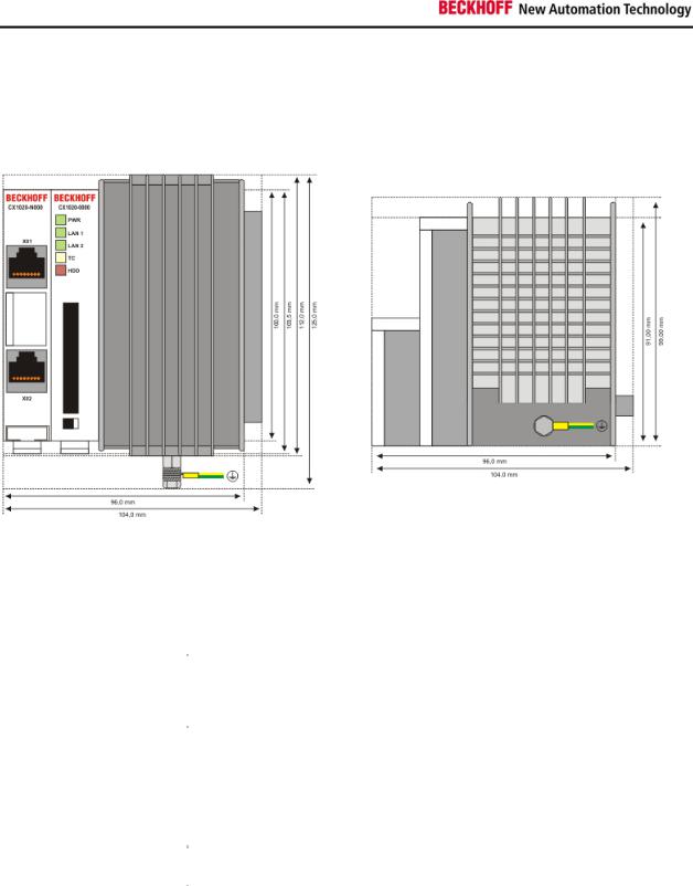
CX1020 Technical Data
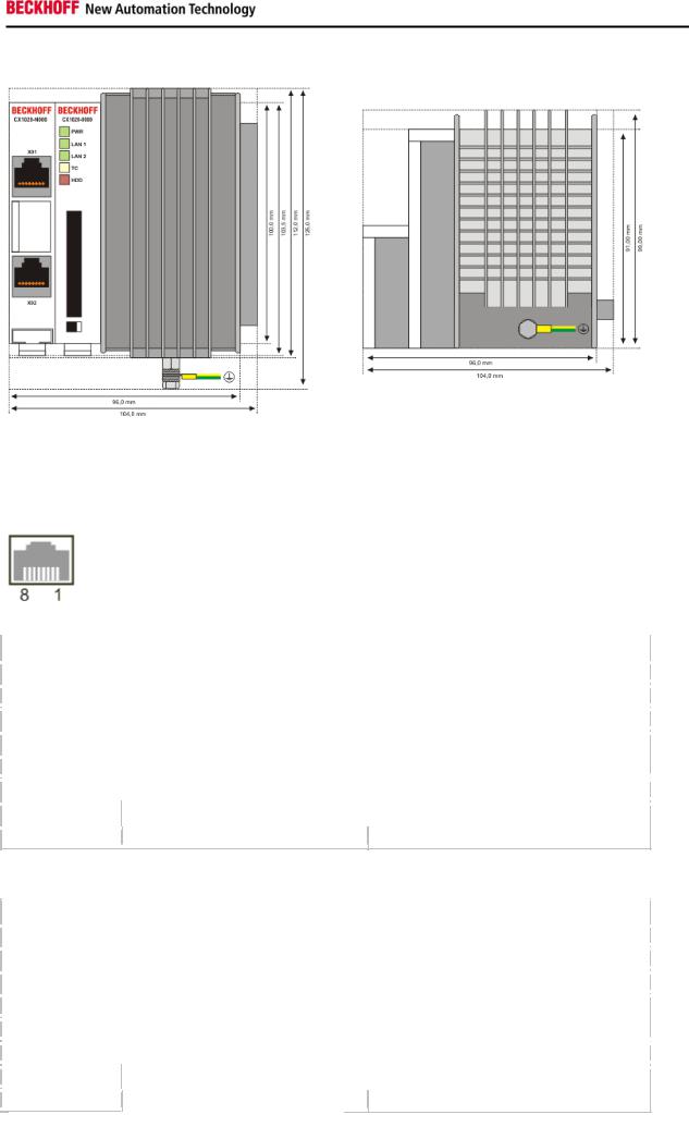
Dimensions:
The basic configuration of the CX1020 includes a 64 MB Compact Flash card. Two Ethernet RJ 45 interfaces are also part of the basic configuration. These interfaces are connected to an internal switch and offer a simple option for creating a line topology without the need for additional Ethernet switches. All other CX family components can be connected via the PC104 interface that is available on both sides.
The passive cooling module is included in the scope of supply. For power supply one of the system power supply modules (CX1100-000x) is needed)
|
Technical data |
|
|
CX1020-0000 |
|
|
|
|
|
||
|
|
|
|
|
|
|
processor |
|
Intel® Celeron® M ULV, 1 GHz clock frequency |
||
|
|
|
|
||
|
Flash memory |
|
64 MB Compact Flash card |
||
|
|
|
|||
|
Internal main memory |
256 MB DDR-RAM (expandable to 512MByte, 1 GB) |
|||
|
|
|
|||
|
Interfaces |
2 x RJ45 (internal switch) |
|||
|
|
|
|||
|
Diagnostics LED |
1 x Power, 2 x LAN link/activity, 1 x TC, 1 x flash access |
|||
|
|
|
|
||
|
Expansion slot |
|
1 x Compact Flash type I+ II insert with eject mechanism |
||
|
|
|
|
||
|
Clock |
|
internal battery-backed clock for time and date |
||
|
|
|
|
||
|
Operating system |
|
Microsoft Windows CE.NET or Microsoft Windows XP Embedded |
||
|
|
|
|||
|
Control software |
TwinCAT PLC Runtime , TwinCAT NC PTP Runtime oder TwinCAT NCI |
|||
|
|
|
|
Runtime |
|
|
System bus |
16 Bit ISA (PC104 standard) |
|||
|
|
|
|||
|
Power supply |
via system bus (through power supply module CX1100-000x) |
|||
|
|
|
|
||
|
Max. power loss |
|
11 W (including CX1100-N0xx systeminterfaces) |
||
|
|
|
|
||
|
Dimensions (W x H x D) |
|
96 mm x 112 mm x 99 mm |
||
|
|
|
|||
|
Wight |
app. 550 g |
|||
|
|
|
|
||
|
Operating/storage |
|
0° C ... +50° C / -25° C ... +85° C |
||
|
temperature |
|
|
|
|
|
Relative humidity |
95% no condensation |
|||
|
|
|
|||
|
Vibration/shock resistance |
conforms to EN 60068-2-6 / EN 60068-2-27/29 |
|||
|
|
|
|||
|
EMC resistance burst / ESD |
conforms to EN 61000-6-2/EN 61000-6-4 |
|||
|
|
|
|
||
|
protection class |
|
IP 20 |
||
|
|
|
|
|
|
12 |
Embedded PC |
Product overview
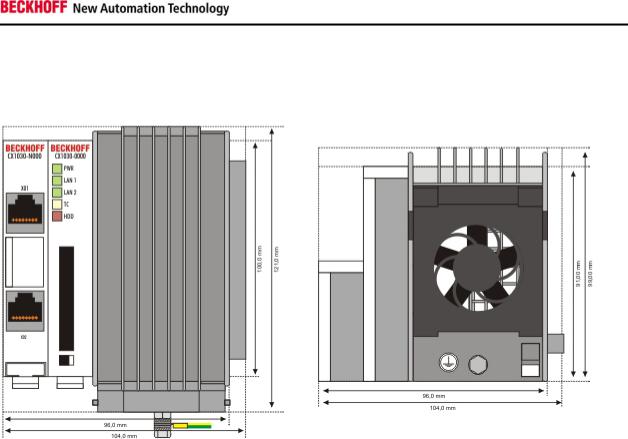
CX1030 Technical Data
Dimensions:
The basic configuration of the CX1030 includes a 64 MB Compact Flash card. Two Ethernet RJ 45 interfaces are also part of the basic configuration. These interfaces are connected to an internal switch and offer a simple option for creating a line topology without the need for additional Ethernet switches. All other CX family components can be connected via the PC104 interface that is available on both sides.
The active cooling module is included in the scope of supply. For power supply one of the system power supply modules (CX1100-001x) is needed)
|
Technical data |
|
|
CX1030-0000 |
|
|
|
|
|
||
|
|
|
|
|
|
|
processor |
|
Intel® Pentium® M, 1.8 GHz clock frequency |
||
|
|
|
|
||
|
Flash memory |
|
64 MB Compact Flash card |
||
|
|
|
|||
|
Internal main memory |
256 MB DDR-RAM (expandable to 512MByte, 1 GB) |
|||
|
|
|
|||
|
Interfaces |
2 x RJ45 (internal switch) |
|||
|
|
|
|||
|
Diagnostics LED |
1 x Power, 2 x LAN link/activity, 1 x TC, 1 x flash access |
|||
|
|
|
|
||
|
Expansion slot |
|
1 x Compact Flash type I+ II insert with eject mechanism |
||
|
|
|
|
||
|
Clock |
|
internal battery-backed clock for time and date |
||
|
|
|
|
||
|
Operating system |
|
Microsoft Windows CE.NET or Microsoft Windows XP Embedded |
||
|
|
|
|||
|
Control software |
TwinCAT PLC Runtime , TwinCAT NC PTP Runtime or TwinCAT NCI |
|||
|
|
|
|
Runtime |
|
|
System bus |
16 Bit ISA (PC104 standard) |
|||
|
|
|
|||
|
Power supply |
via system bus (through power supply module CX1100-000x) |
|||
|
|
|
|
||
|
Max. power loss |
|
11 W (including CX1100-N0xx system interfaces) |
||
|
|
|
|
||
|
Dimensions (W x H x D) |
|
96 mm x 112 mm x 99 mm |
||
|
|
|
|||
|
Wight |
app. 550 g |
|||
|
|
|
|
||
|
Operating/storage |
|
0° C ... +50° C / -25° C ... +85° C |
||
|
temperature |
|
|
|
|
|
Relative humidity |
95% no condensation |
|||
|
|
|
|||
|
Vibration/shock resistance |
conforms to EN 60068-2-6 / EN 60068-2-27/29 |
|||
|
|
|
|||
|
EMC resistance burst / ESD |
conforms to EN 61000-6-2/EN 61000-6-4 |
|||
|
|
|
|
||
|
protection class |
|
IP 20 |
||
|
|
|
|
|
|
Embedded PC |
13 |
Product overview
Note
For operating this unit need a power supply of type CX1100-001x.
14 |
Embedded PC |
Product overview
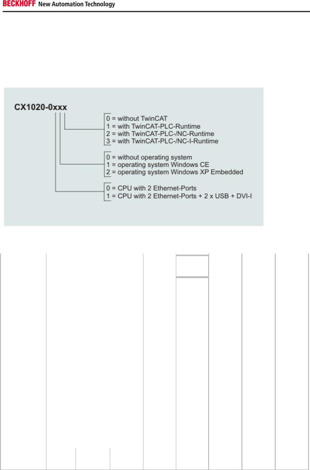
Configurations
The Basic CPU-Module can be ordered with different hardware and software variations. As operating systems there are "Windows CE.NET" and "Windows XP Embedded" available. The TwinCAT automation software transforms a CX1020 system into powerful PLC and Motion Control system that can be operated with or without visualisation.
The order identifier of the basic CPU module is derived as follows:
Following CX1020 configurations are available:
|
|
|
|
no |
|
|
|
|
|
|
|
|
TwinCAT |
|
|
|
TwinCAT |
|
|
|
TwinCAT |
|
|
|
|
|
|
|
|
|
|
|
|
|
|
|
|
|
|
|
|
|
|
||||
Ordering |
|
DVI / |
|
operating |
|
Windows |
|
Windows |
|
no |
|
|
PLC |
|
|
|
NC PTP |
|
|
|
NC I |
|
|
information |
|
USB |
|
system |
|
CE |
|
XPE |
|
TwinCAT |
|
|
Runtime |
|
|
|
Runtime |
|
|
|
Runtime |
|
|
CX1020-0000 |
- |
|
X |
- |
- |
|
X |
- |
|
- |
|
- |
|
|
|||||||||
|
|
|
|
|
|
|
|
|
|
|
|
|
|
|
|||||||||
CX1020-0010 |
- |
- |
|
X |
- |
|
X |
- |
|
- |
|
- |
|
|
|||||||||
|
|
|
|
|
|
|
|
|
|
|
|
|
|
|
|||||||||
CX1020-0011 |
- |
- |
|
X |
- |
- |
|
|
X |
- |
|
- |
|
|
|||||||||
|
|
|
|
|
|
|
|
|
|
|
|
|
|
|
|||||||||
CX1020-0012 |
- |
- |
|
X |
- |
- |
- |
|
|
|
X |
- |
|
|
|||||||||
|
|
|
|
|
|
|
|
|
|
|
|
|
|
|
|||||||||
CX1020-0013 |
- |
- |
|
X |
- |
- |
- |
|
- |
|
|
|
X |
|
|||||||||
|
|
|
|
|
|
|
|
|
|
|
|
|
|
|
|
||||||||
CX1020-0100 |
|
X |
|
X |
- |
- |
|
X |
- |
|
- |
|
- |
|
|
||||||||
|
|
|
|
|
|
|
|
|
|
|
|
|
|
|
|
||||||||
CX1020-0110 |
|
X |
- |
|
X |
- |
|
X |
- |
|
- |
|
- |
|
|
||||||||
|
|
|
|
|
|
|
|
|
|
|
|
|
|
|
|
||||||||
CX1020-0111 |
|
X |
- |
|
X |
- |
- |
|
|
X |
- |
|
- |
|
|
||||||||
|
|
|
|
|
|
|
|
|
|
|
|
|
|
|
|
||||||||
CX1020-0112 |
|
X |
- |
|
X |
- |
- |
- |
|
|
|
X |
- |
|
|
||||||||
|
|
|
|
|
|
|
|
|
|
|
|
|
|
|
|
||||||||
CX1020-0113 |
|
X |
- |
|
X |
- |
- |
- |
|
- |
|
|
|
X |
|
||||||||
|
|
|
|
|
|
|
|
|
|
|
|
|
|
|
|
||||||||
CX1020-0020 |
- |
- |
|
- |
|
X |
|
X |
- |
|
- |
|
- |
|
|
||||||||
|
|
|
|
|
|
|
|
|
|
|
|
|
|
|
|
||||||||
CX1020-0021 |
- |
- |
|
- |
|
X |
- |
|
|
X |
- |
|
- |
|
|
||||||||
|
|
|
|
|
|
|
|
|
|
|
|
|
|
|
|
||||||||
CX1020-0022 |
- |
- |
|
- |
|
X |
- |
- |
|
|
|
X |
- |
|
|
||||||||
|
|
|
|
|
|
|
|
|
|
|
|
|
|
|
|
||||||||
CX1020-0023 |
- |
- |
|
- |
|
X |
- |
- |
|
- |
|
|
|
X |
|
||||||||
|
|
|
|
|
|
|
|
|
|
|
|
|
|
|
|
|
|||||||
CX1020-0120 |
|
X |
- |
|
- |
|
X |
|
X |
- |
|
- |
|
- |
|
|
|||||||
|
|
|
|
|
|
|
|
|
|
|
|
|
|
|
|
|
|||||||
CX1020-0121 |
|
X |
- |
|
- |
|
X |
- |
|
|
X |
- |
|
- |
|
|
|||||||
|
|
|
|
|
|
|
|
|
|
|
|
|
|
|
|
|
|||||||
CX1020-0122 |
|
X |
- |
|
- |
|
X |
- |
- |
|
|
|
X |
- |
|
|
|||||||
|
|
|
|
|
|
|
|
|
|
|
|
|
|
|
|
|
|||||||
CX1020-0123 |
|
X |
- |
|
- |
|
X |
- |
- |
|
- |
|
|
|
X |
|
|||||||
CX1020 Systems with Windows XP Embedded require a Compact Flash card with a capacity of al least 1 GB.
Note:
For detailed information about the software images see the CX10x0 Software Documentation.
Embedded PC |
15 |
Product overview
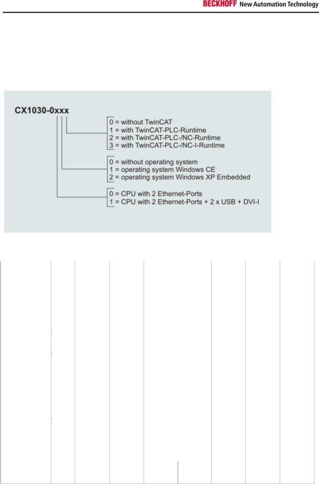
Configurations
The Basic CPU-Module can be ordered with different hardware and software variations. As operating systems there are "Windows CE.NET" and "Windows XP Embedded" available. The TwinCAT automation software transforms a CX1030 system into powerful PLC and Motion Control system that can be operated with or without visualisation.
The order identifier of the basic CPU module is derived as follows:
Following CX1030 configurations are available:
|
|
|
|
|
no |
|
|
|
|
|
|
|
|
TwinCAT |
|
|
|
TwinCAT |
|
|
|
TwinCAT |
|
|
Ordering |
|
DVI / |
|
|
operating |
|
|
Windows |
|
Windows |
no |
|
|
PLC |
|
|
|
NC PTP |
|
|
|
NC I |
|
|
information |
|
USB |
|
|
system |
|
|
CE |
|
XPE |
TwinCAT |
|
|
Runtime |
|
|
|
Runtime |
|
|
|
Runtime |
|
|
|
|
|
|
|
|
|
|
|
|
|
|
|
|
|
||||||||||
CX1030-0000 |
- |
|
|
X |
- |
- |
X |
- |
|
- |
|
- |
|
|
||||||||||
|
|
|
|
|
|
|
|
|
|
|
|
|
|
|
||||||||||
CX1030-0010 |
- |
- |
|
|
X |
- |
X |
- |
|
- |
|
- |
|
|
||||||||||
|
|
|
|
|
|
|
|
|
|
|
|
|
|
|
|
|||||||||
CX1030-0011 |
- |
- |
|
|
X |
- |
- |
|
|
X |
- |
|
- |
|
|
|||||||||
|
|
|
|
|
|
|
|
|
|
|
|
|
|
|
|
|||||||||
CX1030-0012 |
- |
- |
|
|
X |
- |
- |
- |
|
|
|
X |
- |
|
|
|||||||||
|
|
|
|
|
|
|
|
|
|
|
|
|
|
|
|
|||||||||
CX1030-0013 |
- |
- |
|
|
X |
- |
- |
- |
|
- |
|
|
|
X |
|
|||||||||
|
|
|
|
|
|
|
|
|
|
|
|
|
|
|
|
|||||||||
CX1030-0100 |
|
X |
|
|
X |
- |
- |
X |
- |
|
- |
|
- |
|
|
|||||||||
|
|
|
|
|
|
|
|
|
|
|
|
|
|
|
|
|||||||||
CX1030-0110 |
|
X |
- |
|
|
X |
- |
X |
- |
|
- |
|
- |
|
|
|||||||||
|
|
|
|
|
|
|
|
|
|
|
|
|
|
|
|
|
||||||||
CX1030-0111 |
|
X |
- |
|
|
X |
- |
- |
|
|
X |
- |
|
- |
|
|
||||||||
|
|
|
|
|
|
|
|
|
|
|
|
|
|
|
|
|
||||||||
CX1030-0112 |
|
X |
- |
|
|
X |
- |
- |
- |
|
|
|
X |
- |
|
|
||||||||
|
|
|
|
|
|
|
|
|
|
|
|
|
|
|
|
|
||||||||
CX1030-0113 |
|
X |
- |
|
|
X |
- |
- |
- |
|
- |
|
|
|
X |
|
||||||||
|
|
|
|
|
|
|
|
|
|
|
|
|
|
|
||||||||||
CX1030-0020 |
- |
- |
|
- |
|
X |
X |
- |
|
- |
|
- |
|
|
||||||||||
|
|
|
|
|
|
|
|
|
|
|
|
|
|
|
|
|||||||||
CX1030-0021 |
- |
- |
|
- |
|
X |
- |
|
|
X |
- |
|
- |
|
|
|||||||||
|
|
|
|
|
|
|
|
|
|
|
|
|
|
|
|
|||||||||
CX1030-0022 |
- |
- |
|
- |
|
X |
- |
- |
|
|
|
X |
- |
|
|
|||||||||
|
|
|
|
|
|
|
|
|
|
|
|
|
|
|
|
|||||||||
CX1030-0023 |
- |
- |
|
- |
|
X |
- |
- |
|
- |
|
|
|
X |
|
|||||||||
|
|
|
|
|
|
|
|
|
|
|
|
|
|
|
|
|||||||||
CX1030-0120 |
|
X |
- |
|
- |
|
X |
X |
- |
|
- |
|
- |
|
|
|||||||||
|
|
|
|
|
|
|
|
|
|
|
|
|
|
|
|
|
||||||||
CX1030-0121 |
|
X |
- |
|
- |
|
X |
- |
|
|
X |
- |
|
- |
|
|
||||||||
|
|
|
|
|
|
|
|
|
|
|
|
|
|
|
|
|
||||||||
CX1030-0122 |
|
X |
- |
|
- |
|
X |
- |
- |
|
|
|
X |
- |
|
|
||||||||
|
|
|
|
|
|
|
|
|
|
|
|
|
|
|
|
|
||||||||
CX1030-0123 |
|
X |
- |
|
- |
|
X |
- |
- |
|
- |
|
|
|
X |
|
||||||||
CX1030 Systems with Windows XP Embedded require a Compact Flash card with a capacity of al least 1 GB.
Note:
For detailed information about the software images see the CX10x0 Software Documentation.
16 |
Embedded PC |
Product overview
Connections
The basic CPU module is available with different hardware and software options. It is supplied from the power supply unit, so that only the connections are described here.
Basic CPU module with 2 Ethernet RJ 45 interfaces:
RJ 45 interface (socket):
Assignment of the RJ45 interface, Port 1:
|
PIN |
|
|
Signal |
|
|
Description |
|
|
|
|
|
|
|
|||
|
|
|
|
|
|
|
|
|
1 |
|
|
TD + |
|
Transmit + |
|||
|
|
|
|
|
|
|||
2 |
|
|
TD - |
|
Transmit - |
|||
|
|
|
|
|
|
|||
3 |
|
|
RD + |
|
Receive + |
|||
|
|
|
|
|
|
|||
4 |
|
|
connected |
|
not used |
|||
|
|
|
|
|
|
|
|
|
5 |
|
|
|
|
|
|
|
|
|
|
|
|
|
|
|
||
|
|
|
|
|
|
|||
6 |
|
|
RD - |
|
Receive - |
|||
|
|
|
|
|
|
|||
7 |
|
|
connected |
|
not used |
|||
|
|
|
|
|
|
|
|
|
8 |
|
|
|
|
|
|
|
|
TD & RD are exchanged at the hubs or between two PCs.
Assignment of the RJ45 interface, Port 2:
|
PIN |
|
|
Signal |
|
|
Description |
|
|
|
|
|
|
|
|||
|
|
|
|
|
|
|||
1 |
|
|
TD + |
|
Transmit + |
|||
|
|
|
|
|
|
|||
2 |
|
|
TD - |
|
Transmit - |
|||
|
|
|
|
|
|
|||
3 |
|
|
RD + |
|
Receive + |
|||
|
|
|
|
|
|
|||
4 |
|
|
connected |
|
not used |
|||
|
|
|
|
|
|
|
|
|
5 |
|
|
|
|
|
|
|
|
|
|
|
|
|
|
|
||
|
|
|
|
|
|
|||
6 |
|
|
RD - |
|
Receive - |
|||
|
|
|
|
|
|
|||
7 |
|
|
connected |
|
not used |
|||
|
|
|
|
|
|
|
|
|
8 |
|
|
|
|
|
|
|
|
TD & RD are exchanged at the hubs or between two PCs.
Embedded PC |
17 |
Product overview
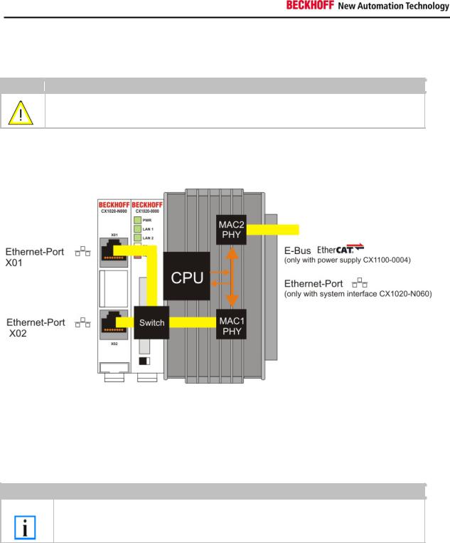
Connection of the Ethernet ports:
Warning
The two Ethernet ports of a basic CPU module must not be connected to the same external switch!
Schematic structure of the network components:
The CX1020 features two MAC blocks. The first one (MAC1) operates the network interfaces for the Ethernet ports. The two outputs are connected via a switch. In this way a line structure can be configured as described below. From an operating system perspective this represents a single connection. The second block (MAC2) operates the extended PC104 bus. The second physical network connection can be utilised via additional system interfaces. This requires either a CX1100-0004 power supply unit or a CX1020-N060 system interface. A connection to the E-bus for EtherCAT terminals is realised via the power supply unit. The CX1020-N060 interface establishes the Ethernet connection, thereby making a further network interface available.
Note
Only for use in LAN, not for connection to telecommunication circuits.
Operating system perspective:
The operating system only sees one of the connections for the network interface. The status is always connected, since the switch is connected directly. The internal connection via the PC104 bus extension is shown as the second interface. If no expansion module is connected, the line is reported as not connected. If the CX1100-00x4 power supply unit is connected, Windows XPe reports "restricted or no connection". This behavior is normal, since Windows itself does not use this interface, and therefore no IP address is allocated. If the CX1020-N060 extension is connected, the connection behaves like a 'normal' network port.
These interfaces are connected to an internal 3-port switch and offer a simple option for creating a line topology without the need for additional Ethernet switches.
18 |
Embedded PC |
Product overview
Basic CPU module with DVI/USB interface:
In addition to the two Ethernet ports, this basic module also features DVI/USB interfaces. The pin assignment of the basic CPU module with two USB and a DVI-I interface is explained under the associated CX1020-N 010 system interface.
Applicable to all basic CPU modules:
LED
The green power LED (PWR) is on if the basic CPU module is connected correctly to a live power supply unit.
Compact Flash slot
Further information can be found under Compact Flash slot.
PC 104 Bus
The PC 104 bus is a standardised bus with 104 ISA signals for compact embedded systems.
Embedded PC |
19 |
Product overview
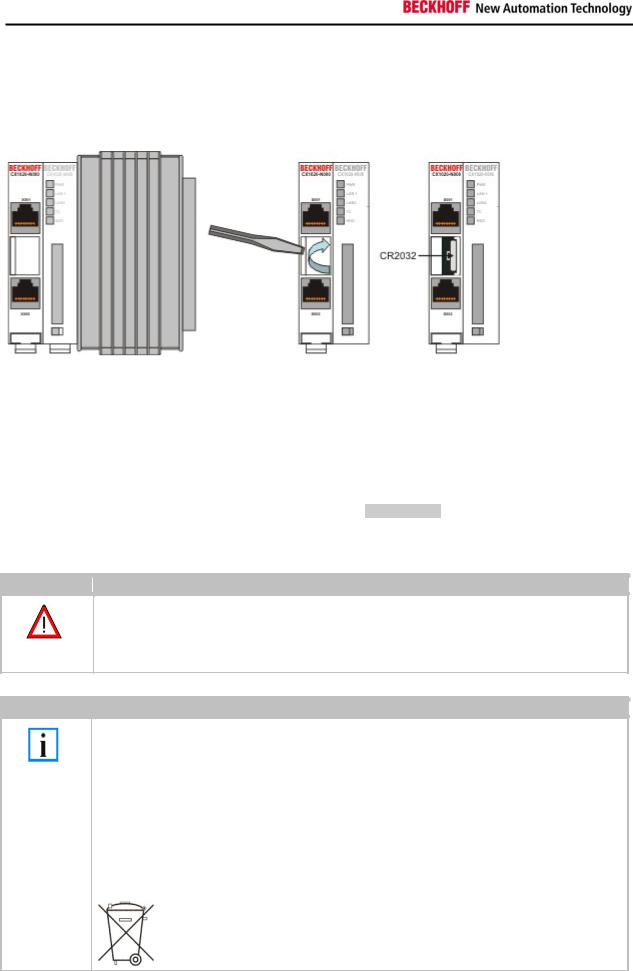
Battery compartment
The battery compartment is located on the left-hand side of the CPU module, between the two Ethernet ports. It can be opened with the aid of a screwdriver (proceed carefully in order to avoid damage).
The battery is a CR2032 type from Panasonic with the following specification:
|
Battery type |
|
Electrical properties |
|
Standard |
|
|
|
|
Dimensions |
|
|
|
||
|
|
(at 20° C) |
|
|
|
|
|
|
|
|
|||||
|
|
|
charge |
|
|
|
|
|
|
|
|
|
|||
|
|
|
|
|
|
|
|
|
|
|
|
|
|
|
|
|
|
|
|
|
|
|
|
|
|
|
|
|
|
|
|
|
|
|
nominal |
nominal |
|
continuous |
|
Diameter |
|
Height |
|
|
Weight |
|
|
|
|
|
voltage |
capacity |
|
load |
|
|
|
|
|
||||
|
|
|
|
|
|
|
|
|
|
|
|
||||
|
CR2032 |
3.0 V |
225 mAh |
|
0.20 mA |
|
20.0 mm |
|
3.20 mm |
|
3.1 g |
||||
|
|
|
|
|
|
|
|
|
|
|
|
|
|
|
|
Danger
Replace Battery Part. No. CR2032 manufactured by Sanyo or Panasonic Only. Use of Another Battery May Present A Risk Of Fire Or Explosion.
WARNING, Battery may explode if mistreated. Do Not Recharge, Disassemble or Dispose of in fire.
Note
The battery must be changed every 5 years.
Spare batteries can be ordered from Beckhoff Service.
Battery-recycling:
Used batteries must must be disposed of in accordance with national electronics scrap regulations.
Used batteries may contain harmful substances or heavy metal that can harm the environment and health. Batteries will be recycled. They contain important commodities as iron, zinc, nickel or manganese.
The environment and Beckhoff thank for your understanding
20 |
Embedded PC |
Product overview
Compact Flash slot
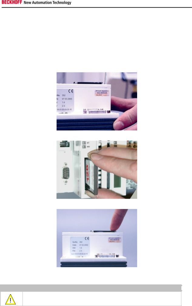
A Compact Flash slot is provided at the front of module. This enables an additional Compact Flash memory medium (format I or II) to be operated. The change - in case of the Basic CPU module CF slot - is only allowed while the system is powered down - otherwise the system could crash. In case of using the CF-slot extension (CXxxxx-A001) the CF card can be removed after signing out the media from the system. The card can be removed for maintenance or to extend the system storage capacity. The Compact Flash cards (CF cards) are available as accessories with different storage capacities.
As example the following pictures show the handling of the CF cards with a CX1000 system. Activating the eject mechanism below the slot with a screwdriver causes the card to be ejected by approx. 4 mm (FIGURE 1), so that it can be pulled out (FIGURE 2). If the card is pushed in (FIGURE 3), the eject mechanism will re-engage. The card is positioned correctly, if it is located approx. 1 mm lower than the front of the housing.
FIG1: Ejecting the CF card
FIG2: Removing the CF card
FIG3: Inserting the CF card
Warning
The Compact Flash slot is a memory interface, not an I/O type CF slot.
Embedded PC |
21 |
Product overview
Compact-Flash card
The Compact Flash card (CF card) is a non-volatile memory medium.
Data to be retained in the event of a power failure should be saved on the CF card. The CF card operates similar to a hard disk.
Warning
It is recommended only use CF cards supplied by Beckhoff Automation GmbH.
The CF cards are made for industrial use. They possess a higher number of read / write cycles and an enhance temperature range (up to + 85°C).
A proper operation of the CX-System can only be guaranteed with the use of CF cards from Beckhoff Automation GmbH!
22 |
Embedded PC |
Product overview
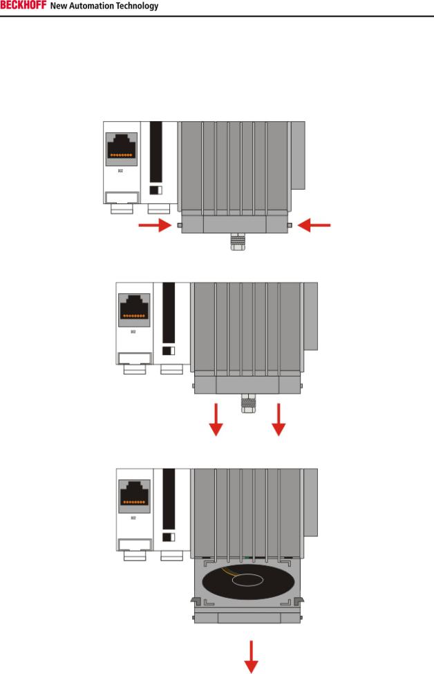
Fan cartridge
On the lower side of the heat sink resides the fan cartridge. The fan is necessary to operate the unit in industrial environment. Due to the continuous operation the fan needs replacement every 5 years.
0.Shut down the system and switch off power.
1.Press the mounting links on the sides in the direction of the arrows and keep them pressed
2. Move the front of the cartridge down.
3. Take the cartridge towards the front. The cartridge is now removed.
Embedded PC |
23 |
Product overview
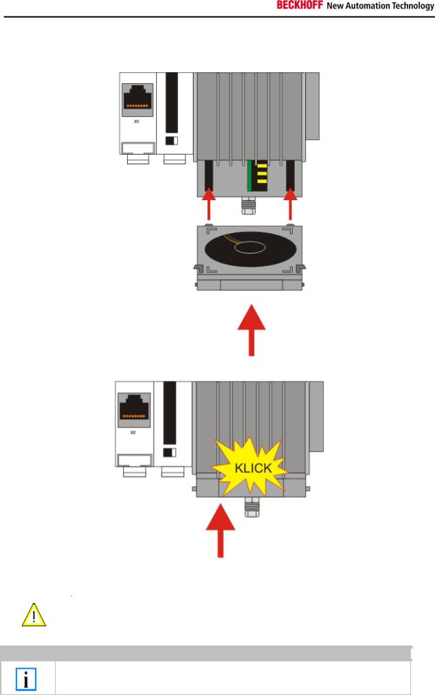
4. Open the packaging of the new fan cartridge and take out the new cartridge. Hold the cartridge in front of the mounting notches.Take care that the notches fit the holes in the back of the housing.
5. Move the cartridge up until it snaps in the housing with a click.
|
Attention |
|
|
The CPU can be damaged |
|
|
|
|
|
||
|
|
|
|
|
|
|
|
|
|
Operation with a defective fan or no fan damage the CPU! |
|
|
|
|
|
|
|
Note
The fan must be changed every 5 years.
Replacement fan cartridges can be orders via Beckhoff Service.
24 |
Embedded PC |
Product overview
Adapter RAM Hardware address overview
available memory addresses CX1020: D0000-DFFFF (hex)
|
Base Address |
|
|
|
End Address |
|
|
|
|
|
Access |
|
|
|
|
(hex) |
|
|
|
(hex) |
|
|
Size(Bytes)(hex) |
|
|
Type |
|
Description |
|
|
|
|
|
|
|
|
|
|
||||||
|
D0000 |
|
D0FFF |
1000 |
|
R/W |
CX1100-0002/3 Dual Ported RAM |
|
||||||
|
|
|
|
|
|
|
|
|
|
|
||||
|
D1000 |
|
|
D100F |
10 |
|
|
R/W |
CX1100 Auxiliary Control Block( LCD |
|
||||
|
|
|
|
|
|
|
|
|
|
|
|
|
Display, misc. registers) |
|
|
D1010 |
|
|
D101F |
10 |
|
|
R/W |
CX1100-0900 UPS Control Block |
|
||||
|
|
|
|
|
|
|
|
|
||||||
|
D2000 |
|
D3FFF |
2000 |
|
R/W |
CX1100 Non Volatile RAM |
|
||||||
|
|
|
|
|
|
|
|
|
||||||
|
D4000 |
|
D5FFF |
2000 |
|
R/W |
CX1500-M310 Profibus Master |
|
||||||
|
|
|
|
|
|
|
|
|
|
|
|
|
DPRAM |
|
|
D6000 |
|
D7FFF |
2000 |
|
R/W |
CX1500-M510 CANopen Master |
|
||||||
|
|
|
|
|
|
|
|
|
|
|
|
|
DPRAM |
|
|
D8000 |
|
D9FFF |
2000 |
|
R/W |
CX1500-M520 DeviceNet Master |
|
||||||
|
|
|
|
|
|
|
|
|
|
|
|
|
DPRAM |
|
|
DA000 |
|
|
DBFFF |
2000 |
|
|
R/W |
CX1500-M200 Lightbus Master |
|
||||
|
|
|
|
|
|
|
|
|
|
|
|
|
DPRAM |
|
|
DC000 |
|
DDFFF |
2000 |
|
R/W |
CX1500-M750 Sercos Master DPRAM |
|
||||||
For some fieldbus connections (all Slave modules) the base addresses are mapped in the memory region upper DFFFF(hex). So these modules must be ordered with other base addresses. The same situation takes place if more than two or more master modules of same type are used (for more see note below). The order numbers for the modules are:
|
order number |
|
|
alternative ISA address |
|
|
|
|
|
|
|
|
|
|
Master connection |
|
|
|
|
|
|
|
|
|
|||
|
CX1500-Mxxx-0001 |
D4000 |
|
|||
|
|
|
|
|||
|
CX1500-Mxxx-0002 |
D6000 |
|
|||
|
|
|
|
|||
|
CX1500-Mxxx-0003 |
D8000 |
|
|||
|
|
|
|
|||
|
CX1500-Mxxx-0004 |
DA000 |
|
|||
|
|
|
|
|||
|
CX1500-Mxxx-0005 |
DC000 |
|
|||
|
|
|
|
|
|
|
|
Slave connection |
|
|
|
|
|
|
|
|
|
|||
|
CX1500-Bxxx-0001 |
D4000 |
|
|||
|
|
|
|
|||
|
CX1500-Bxxx-0002 |
D6000 |
|
|||
|
|
|
|
|||
|
CX1500-Bxxx-0003 |
D8000 |
|
|||
|
|
|
|
|||
|
CX1500-Bxxx-0004 |
DA000 |
|
|||
|
|
|
|
|||
|
CX1500-Bxxx-0005 |
DC000 |
|
|||
Replace xxx with the following number for the requested fieldbus system:
200 for Lightbus
310 for Profibus
510 for CAN-open
520 for DeviceNet
750 for Sercos (only Master connection available)
Note
Two connection modules (master or slave) can be used simultaneously.
If more than two connections are needed call Beckhoff Automation GmbH for further information.
Embedded PC |
25 |
Product overview
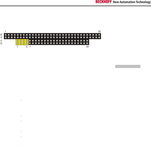
PC 104 Bus
The PC 104 bus is a standardized bus with 104ISA signals for compact embedded systems.
For the functionality of the CX1020 modules eight further signals have been added (here marked with color). Pin assignment of 16 Bit PC 104 Bus:
|
Pin |
|
|
|
|
Row C4 |
|
Row D4 |
|
|
|
|
|
|
|||
|
Number |
|
Row A |
Row B |
|
|
||
|
|
|
|
|
|
|||
1 |
|
IOCHCHK* |
GND |
GND |
GND |
|||
|
|
|
|
|
|
|
||
2 |
|
SD7 |
RESETDRV |
|
SBHE* |
MEMCS16* |
||
|
|
|
|
|
|
|
||
3 |
|
SD6 |
+5V |
|
LA23 |
IOCS16* |
||
|
|
|
|
|
|
|
||
4 |
|
SD5 |
IRQ9 |
|
LA22 |
IRQ10 |
||
|
|
|
|
|
|
|
||
5 |
|
SD4 |
n.c. (+12V internal) |
|
LA21 |
IRQ11 |
||
|
|
|
|
|
|
|||
6 |
|
SD3 |
DRQ2 |
LA20 |
IRQ12 |
|||
|
|
|
|
|
|
|
||
7 |
|
SD2 |
n.c. (+5V internal) |
|
LA19 |
IRQ13 |
||
|
|
|
|
|
|
|
||
8 |
|
SD1 |
ENDXFR* |
|
LA18 |
IRQ14 |
||
|
|
|
|
|
|
|
||
9 |
|
SD0 |
+12V |
|
LA17 |
DACK0* |
||
|
|
|
|
|
|
|||
10 |
|
IOCHRDY |
(KEY)² |
MEMR* |
DRQ0 |
|||
|
|
|
|
|
|
|
||
11 |
|
AEN |
SMEMW* |
|
MEMW* |
DACK5* |
||
|
|
|
|
|
|
|
||
12 |
|
SA19 |
SMEMR* |
|
SD8 |
DRQ5 |
||
|
|
|
|
|
|
|
||
13 |
|
SA18 |
IOW* |
|
SD9 |
DACK6* |
||
|
|
|
|
|
|
|
||
14 |
|
SA17 |
IOR* |
|
SD10 |
DRQ6 |
||
|
|
|
|
|
|
|||
15 |
|
SA16 |
DACK3* |
SD11 |
DACK7* |
|||
|
|
|
|
|
|
|||
16 |
|
SA15 |
DRQ3 |
SD12 |
DRQ7 |
|||
|
|
|
|
|
|
|||
17 |
|
SA14 |
DACK1* |
SD13 |
+5V |
|||
|
|
|
|
|
|
|
||
18 |
|
SA13 |
DRQ1 |
|
SD14 |
MASTER* |
||
|
|
|
|
|
|
|
||
19 |
|
SA12 |
REFRESH* |
|
SD15 |
GND |
||
|
|
|
|
|
|
|
||
20 |
|
SA11 |
SYSCLK |
|
(KEY)² |
GND |
||
|
|
|
|
|
|
|
||
21 |
|
SA10 |
IRQ7 |
-- |
|
-- |
||
|
|
|
|
|
|
|
||
22 |
|
SA9 |
IRQ6 |
-- |
|
-- |
||
|
|
|
|
|
|
|
||
23 |
|
SA8 |
IRQ5 |
-- |
|
-- |
||
|
|
|
|
|
|
|
||
24 |
|
SA7 |
IRQ4 |
-- |
|
-- |
||
|
|
|
|
|
|
|
||
25 |
|
SA6 |
IRQ3 |
-- |
|
-- |
||
|
|
|
|
|
|
|
||
26 |
|
SA5 |
DACK2* |
-- |
|
-- |
||
|
|
|
|
|
|
|
||
27 |
|
SA4 |
TC |
-- |
|
-- |
||
|
|
|
|
|
|
|
||
28 |
|
SA3 |
BALE |
-- |
|
-- |
||
|
|
|
|
|
|
|
||
29 |
|
SA2 |
+5V |
-- |
|
-- |
||
|
|
|
|
|
|
|
||
30 |
|
SA1 |
OSC |
-- |
|
-- |
||
|
|
|
|
|
|
|
||
31 |
|
SA0 |
GND |
-- |
|
-- |
||
|
|
|
|
|
|
|
||
32 |
|
GND |
GND |
-- |
|
-- |
||
|
|
|
|
|
|
|
|
|
26 |
Embedded PC |

Product overview
Remarks:
1.B10 and C19 are key locations.
2.Signal timing and function are as specified in ISA specification.
3.Signal source/sink current differs from ISA values.
4.Negative voltages are not supported.
5.in the specification the pins are counted from 0 to 19
Assignment on the 8 additional pins
|
Pin number (yellow fields) |
|
|
Row C |
|
Row D |
|
|
|
|
|||
|
|
|
|
|
||
1 |
|
|
LAN TX- |
LAN TX+ |
||
|
|
|
|
|
||
2 |
|
|
LAN RX- |
LAN RX+ |
||
|
|
|
|
|
||
3 |
|
|
USB D- |
USB D+ |
||
|
|
|
|
|
||
4 |
|
|
SMBDAT |
SMBCLK |
||
|
|
|
|
|
|
|
|
Note: |
|
|
|
|
|
|
Further information to PC104 Bus can be found in the |
datasheet or under http://www.pc104.org. |
||||
Embedded PC |
27 |

Product overview
System interfaces
Technical Data
Dimensions:
Like for the CX1000, a number of optional interface modules are available for the basic CX1020 CPU module that can be installed ex works. The following interfaces are available:
28 |
Embedded PC |
 Loading...