


 Loading...
Operating instructions for
Beckhoff CP9030 / CP9035 CP-Link Cards
Version: 1.5
Date: 2009-10-05

General instructions |
|
|
|
Table of contents |
|
1. General instructions |
5 |
Notes on the Documentation |
5 |
Liability Conditions |
5 |
2. Beckhoff CP-Link System Description |
6 |
CP-Link |
6 |
Example: CP-Link "Single" Connection |
7 |
Multi CP-Link |
8 |
Example: CP-Link "Double" Connection |
9 |
3. Technical Data CP9030 |
10 |
Layout of the BECKHOFF CP-Link Card |
10 |
Cable and jumper configurations |
16 |
Advantech SBC |
16 |
Bayview 50 / 52 Graphic Card |
16 |
Boser HS6237 SBC |
16 |
Inside Technology 686LCD SBC |
17 |
MITAC 251 SBC |
17 |
Vampower 7 Graphic Card |
17 |
Vampower 8 Graphic Card |
17 |
View of the CP9030 Slot Cover |
18 |
CP9030 DPRAM Memory Allocation |
19 |
CP9030 card pin assignments |
22 |
Description of the Status LEDs |
26 |
Jumper Assignments |
27 |
ISA bus current consumption |
27 |
4. Technical Data CP9035 |
28 |
Layout of the BECKHOFF CP-Link Card |
28 |
Cable and jumper configurations |
30 |
CP9035 card pin assignments |
30 |
Description of the Status LEDs |
33 |
Jumper Assignments |
34 |
Current consumption |
34 |
View of the CP9035 Slot Cover |
35 |
5. Technical Data CP9035 with DVI-Add Card |
36 |
Layout of the CP9035 with DVI-Add Card |
36 |
6. Multi CP-Link Cable-sets |
37 |
7. CP-Link connecting cable |
38 |
8. Appendix |
40 |
Beckhoff Support & Service |
40 |
Beckhoff branches and partner companies |
40 |
Beckhoff Headquarters |
40 |
Beckhoff Support |
40 |
Beckhoff Service |
40 |
CP9030 / CP9035 |
3 |

General instructions
4 |
CP9030 / CP9035 |

General instructions
General instructions
Notes on the Documentation
This description is only intended for the use of trained specialists in control and automation engineering who are familiar with the applicable national standards. It is essential that the following notes and explanations are followed when installing and commissioning these components.
Liability Conditions
The responsible staff must ensure that the application or use of the products described satisfy all the requirements for safety, including all the relevant laws, regulations, guidelines and standards.
The documentation has been prepared with care. The products described are, however, constantly under development. For that reason the documentation is not in every case checked for consistency with performance data, standards or other characteristics. None of the statements of this manual represents a guarantee (Garantie) in the meaning of § 443 BGB of the German Civil Code or a statement about the contractually expected fitness for a particular purpose in the meaning of § 434 par. 1 sentence 1 BGB. In the event that it contains technical or editorial errors, we retain the right to make alterations at any time and without warning. No claims for the modification of products that have already been supplied may be made on the basis of the data, diagrams and descriptions in this documentation.
© This documentation is copyrighted. Any reproduction or third party use of this publication, whether in whole or in part, without the written permission of Beckhoff Automation GmbH, is forbidden.
CP9030 / CP9035 |
5 |
Beckhoff CP-Link System Description
Beckhoff CP-Link System Description
System
LCD grafic- |
CP-Link |
CP-Link |
TFT display |
|
controller |
PC |
Control Panel |
||
|
||||
|
multiplexer |
multiplexer |
|
|
|
|
|
Touch screen |
Motherboard
-Keyboard
-Serial interface
-Diskette drive
CP-Link
giga bit serial link
 PC keyboard
EinschubEinschubEinschubEinschubEinschub PLC keys Streifen Streifen Streifen Streifen Streifen
with LED
12 V DC from PC power supply
2 coaxial cable (max. 100 m)
Pushbutton
Extension
Diskette |
drive |
RS232 interface
PS/2 mouse interface
5V power supply
|
CP-Link |
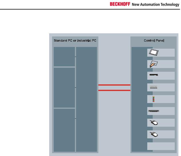
Flexibility |
Maximum flexibility for location of the Control Panel on the equipment. |
|
The connection from the Control Panel to the PC itself is made via CP Link, |
|
a transmission technology having a data rate in the gigabit range. CP Link |
|
implements transmission segments up to 100 m on a twin-core coaxial |
|
cable. No additional power supply is needed. The CP-Link Interface is |
|
implemented as an ISA and PCI bus plug-in card and is thus usable in any |
|
PC. The PC is also equipped with a graphics card providing an LCD |
|
interface. The PC ports for LC display, keyboard, COM ports, PS/2 mouse |
|
and floppy drive are converted by the CP-Link plug-in card into a high- |
|
frequency serial signal and transmitted via coaxial cable to the Control |
|
Panel. The CP-Link Interface in the Control Panel re-converts the serial |
|
signal for the original PC ports, to which the components of the Control |
|
Panel, such as keyboard, LC display, touch screen, touch pad, PS/2 mouse |
|
and floppy drive are connected, but at a 100 meters longer distance than |
|
would ordinarily be possible. There is a CP-Link channel for each direction |
|
of the communication between the Control Panel and the PC. Two coaxial |
|
cables are laid for this reason. |
6 |
CP9030 / CP9035 |
Beckhoff CP-Link System Description
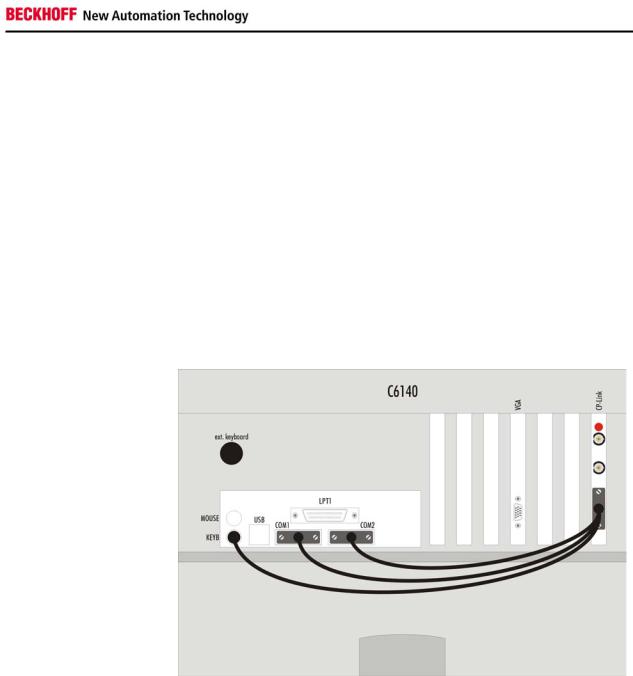
Example: CP-Link "Single" Connection
One Control Panel with Touchpad and Touchscreen
The signals required for the touchpad (RS232) and touchscreen (RS232) are distributed through connector ST303 to the computer's individual COM ports. The sequence of the COM ports only has to be maintained for the installation of the corresponding drivers. The keyboard signals are also passed via ST303 to the motherboard's own keyboard connection. Switching between the various keyboards (Control Panel membrane keypad, a keyboard socket which may be present on the Control Panel, and external keyboard connection on the PC) is performed on the CP-Link board, which means that it is possible to operate all the keyboards in parallel.
The BNC cables are connected to the CP-Link A and CP-Link B connectors on the CP-Link card. Orientation is aided by a red mark on the card. The cable types and the corresponding lengths are described below.
Fig. 3
CP9030 / CP9035 |
7 |
Beckhoff CP-Link System Description
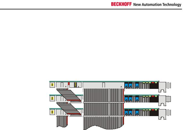
Multi CP-Link
Up to three Control Panels Up to three Control Panels can be connected to one PC. Each Control Panel can be installed at a distance of up to 100 m from the PC, which ensures maximum flexibility in locating the Control Panel on the equipment.
For each Control Panel, one CP-Link insert card is installed in the PC.
If a number of pointing devices or interfaces (touchpad, touchscreen, RS232) are used with the Control Panel it is necessary for the PC to have a corresponding number of interfaces.
Assembly and connections in the PC
CP-LINK 03 |
CP-LINK 02 |
CP-LINK 01 |
ext. keyboard
to graphiccard
All displays show the same image. This requires all the displays to have the same format.
Data can be entered on the PC keyboard, on the keyboard of one of the Control Panels or on a standard keypad connected to one of the Control Panels or directly to the PC.
8 |
CP9030 / CP9035 |
Beckhoff CP-Link System Description
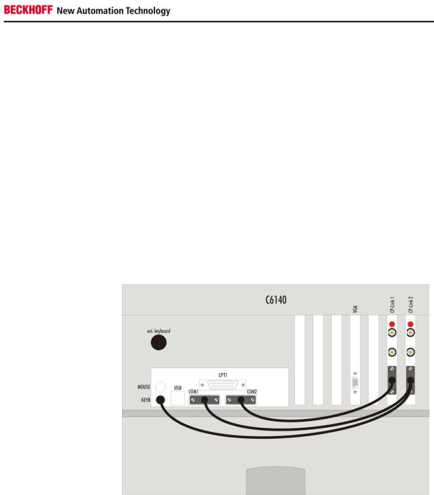
Example: CP-Link "Double" Connection
One Control Panel with Touchscreen and one Control Panel with Touchpad
If we assume that the Control Panel with touchpad is connected to CP-Link 1 and that the Control Panel with touchscreen is connected to CP-Link 2, then the signals from the one Control Panel for the touchpad (RS232) from CP-Link 1 are passed to COM2, and the signals from the touchscreen (RS232) of the other Control Panel are passed to COM 1. The keyboard cable to the motherboard must be plugged into the card on the outside (CPLink 2). Further, a 1:1 connection from ST305 (CP-Link 1) to ST304 (CPLink 2) is required in order to pass the keyboard signals arising from CPLink 1 on to CP-Link 2.
The drivers must be installed in accordance with the assignments of the touchpad and touchscreen.
The BNC cables are connected to the "CP-Link A" and "CP-Link B" connectors on the CP-Link card. Orientation is aided by a red mark on the card. The cable types and the corresponding lengths are described below.
Fig. 4
CP9030 / CP9035 |
9 |

Technical Data CP9030
Technical Data CP9030
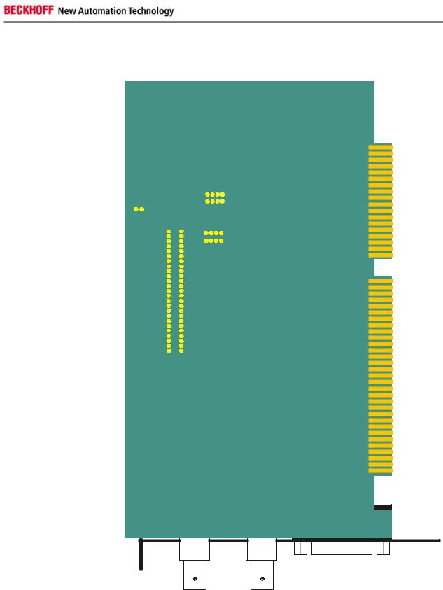
Layout of the BECKHOFF CP-Link Card
CP9030_3
Fig. 5
CP9030_3
LED LED LED LED LED 01 02 03 04 05
LED 06 LED 07
|
|
|
|
A |
|
|
|
|
|
|
|
|
B |
|
|||
|
|
|
|
CP-Link |
|
|
|
|
|
|
|
|
CPLink- |
|
|||
|
|
|
|
|
|
|
|
|
|
|
|
|
|
|
|
|
|
|
|
|
|
|
|
|
|
|
|
|
|
|
|
|
|
|
|
|
|
|
|
|
|
|
|
|
|
|
|
|
|
|
|
|
|
|
|
|
|
|
|
|
|
|
|
|
|
|
|
|
|
|
|
|
|
|
|
|
|
|
|
|
|
|
|
|
|
|
|
|
|
|
|
|
|
|
|
|
|
|
|
|
|
|
|
|
|
|
|
|
|
|
|
|
|
|
|
|
|
|
|
|
|
|
|
|
|
|
|
|
|
|
|
|
|
|
|
|
|
|
|
|
|
|
|
|
|
|
|
|
|
|
|
|
|
|
|
|
|
|
|
|
|
|
|
|
|
|
|
|
|
|
|
|
|
|
|
|
|
|
|
|
|
|
|
|
|
|
|
|
|
|
|
|
|
|
|
|
|
|
|
|
|
|
|
|
|
|
|
|
|
|
|
|
|
|
|
|
|
|
|
|
|
|
|
|
|
|
|
|
|
|
|
|
|
|
|
|
|
|
|
|
|
|
|
|
|
|
|
|
|
|
|
|
|
|
|
|
|
|
|
|
|
|
|
|
|
|
|
|
|
|
|
|
|
|
|
|
|
|
|
|
|
|
|
|
|
|
|
|
|
|
|
|
|
|
|
|
|
|
|
|
|
|
|
|
|
|
|
|
|
|
|
|
|
|
|
|
|
|
|
|
|
|
|
|
|
|
|
|
|
|
|
|
|
|
|
|
|
|
|
|
|
|
|
|
|
|
|
|
|
|
|
|
|
|
|
|
|
|
|
|
|
|
|
|
|
|
|
|
|
|
|
|
|
|
|
|
|
|
|
|
|
|
|
|
|
|
|
|
|
|
|
|
|
|
|
|
|
|
|
|
|
|
|
|
|
|
|
|
|
|
|
|
|
|
|
|
|
|
|
|
|
|
|
|
|
|
|
|
|
|
|
|
|
|
|
|
|
|
|
|
|
|
|
|
|
|
|
|
|
|
|
|
|
|
|
|
|
|
|
|
|
|
|
|
|
|
|
|
|
|
|
|
|
|
|
|
|
|
|
|
|
|
|
|
|
|
|
|
|
|
|
|
|
|
|
|
|
|
|
|
|
|
|
|
|
|
|
|
|
|
|
|
|
|
|
|
|
|
|
|
|
|
303TS |
ST301 |
ST302 |
JU201 |
JU202 |
 ST202
ST202

JU203
ST202
IC201


 Bayview
Version 1.1

104UJ
204UJ
ST304 ST305 |
ON DIP ON DIP |
12 3 4 12 3 4 5 6 7 8 |
SW500SW400J300 |
603TS |
|
302TS |
|
|
|
||
IC500 |
Version1.730 |
01.11.1998 |
404TS |
ST501 |
|
10 |
CP9030 / CP9035 |
Technical Data CP9030
Configuration jumpers on the CP9030_3
Fig. 6
J261
J260
J249 |
J250 |
J247 |
J248 |
J245 |
J246 |
J243 |
J244 |
J241 |
J242 |
J239 |
J240 |
J237 |
J238 |
J235 |
J236 |
J233 |
J234 |
J231 |
J232 |
J229 |
J230 |
J227 |
J228 |
J225 |
J226 |
J223 |
J224 |
J221 |
J222 |
J219 |
J220 |
J217 |
J218 |
J215 |
J216 |
J213 |
J214 |
J211 |
J212 |
J209 |
J210 |
J207 |
J208 |
J205 |
J206 |
J203 |
J204 |
J201 |
J202 |
J257 J258 J262 J263 J255 J256 J264 J265 J253 J254 J266 J267 J251 J252 J268 J269
BECKHOFF CP9030_3
|
|
|
|
|
|
|
|
|
|
|
|
|
|
|
|
|
|
|
|
|
|
|
|
|
|
|
|
|
|
|
|
|
|
|
|
|
|
|
|
|
|
|
|
|
|
|
|
|
|
|
|
|
|
|
|
|
|
|
|
|
|
|
|
|
|
|
|
CP9030 / CP9035 |
11 |
|||||||||||||||
Technical Data CP9030
CP9030_4
Fig. 7
LED03LED04LED05 |
CP90304 |
LED06 |
LED07 |
CP-LinkA |
CP-LinkB |
LED02 |
|
|
|
|
|
LED01 |
|
|
|
|
|
 JU201 JU202 JU200
|
303TS |
ST301 |
ST302 |
 ST202
ST202

 ST204
ST204
104UJ
204UJ
IC201 |
Bayview |
Version1.1 |
ST304 ST305 |
205J |
105J |
|
ON DIP |
12 3 4 5 6 7 8 |
SW400J300 |
|
603TS |
|
006TS |
|
|
|
||
|
|
|
|
|
|
|
|
|
|
|
|
|
|
|
|
|
|
|
|
|
|
|
|
|
|
|
|
|
|
|
|
|
|
|
|
|
|
|
|
|
|
|
|
|
|
|
|
|
|
|
|
|
|
|
|
|
|
|
|
|
|
|
|
|
|
|
|
|
|
|
|
|
|
|
|
|
|
|
|
IC500 |
|
|
Version1.730 |
|
|
|
|
|
|
|
|
|
|||
|
|
|
|||||
|
|
||||||
|
|
||||||
|
|
|
|
||||
|
|
|
|
||||
|
|
|
|
|
|
|
|
|
|
|
|
|
|
|
|
404TS |
ST501 |
|
12 |
CP9030 / CP9035 |

Technical Data CP9030
Configuration jumpers on the CP9030_4
Fig. 8
J261
J260
J249 |
J250 |
J247 |
J248 |
J245 |
J246 |
J243 |
J244 |
J241 |
J242 |
J239 |
J240 |
J237 |
J238 |
J235 |
J236 |
J233 |
J234 |
J231 |
J232 |
J229 |
J230 |
J227 |
J228 |
J225 |
J226 |
J223 |
J224 |
J221 |
J222 |
J219 |
J220 |
J217 |
J218 |
J215 |
J216 |
J213 |
J214 |
J211 |
J212 |
J209 |
J210 |
J207 |
J208 |
J205 |
J206 |
J203 |
J204 |
J201 |
J202 |
J257 J258 J262 J263 J255 J256 J264 J265 J253 J254 J266 J267 J251 J252 J268 J269
LO100
BECKHOFF CP9030_4
|
|
|
|
|
|
|
|
|
|
|
|
|
|
|
|
|
|
|
|
|
|
|
|
|
|
|
|
|
|
|
|
|
|
|
|
|
|
|
|
|
|
|
|
|
|
|
|
|
|
|
|
|
|
|
|
|
|
|
|
|
|
|
|
|
|
|
|
CP9030 / CP9035 |
13 |
|||||||||||||||
Loading...