


Application guide
TwinSAFE
Version: 1.3.1
Date: 2012-02-01

Table of contents
Table of contents
1 |
Foreword |
4 |
||
|
1.1 |
Notes on the manual |
4 |
|
|
|
1.1.1 |
Disclaimer |
4 |
|
|
1.1.2 |
Trademarks |
4 |
|
|
1.1.3 |
Patent Pending |
4 |
|
|
1.1.4 |
Copyright |
4 |
|
1.2 |
Safety instructions |
5 |
|
|
|
1.2.1 |
Delivery state |
5 |
|
|
1.2.2 Operator's obligation to exercise diligence |
5 |
|
|
|
1.2.3 Description of safety symbols |
6 |
|
|
|
1.2.4 |
Explanation of terms |
6 |
2 |
Circuit examples |
7 |
||
|
2.1 |
ESTOP function variant 1 (Category 3, PL d) |
7 |
|
|
|
2.1.1 Parameters of the safe input and output terminals |
7 |
|
|
|
2.1.2 Block formation and safety loops |
8 |
|
|
|
2.1.3 |
Calculation |
8 |
|
2.2 |
ESTOP function variant 2 (Category 3, PL d) |
13 |
|
|
|
2.2.1 Parameters of the safe input and output terminals |
13 |
|
|
|
2.2.2 Block formation and safety loops |
14 |
|
|
|
2.2.3 |
Calculation |
14 |
|
2.3 |
ESTOP function variant 3 (Category 4, PL e) |
19 |
|
|
|
2.3.1 Parameters of the safe input and output terminals |
19 |
|
|
|
2.3.2 Block formation and safety loops |
20 |
|
|
|
2.3.3 |
Calculation |
20 |
|
2.4 |
ESTOP function variant 4 (Category 4, PL e) |
25 |
|
|
|
2.4.1 Parameters of the safe input and output terminals |
25 |
|
|
|
2.4.2 Block formation and safety loops |
26 |
|
|
|
2.4.3 |
Calculation |
26 |
|
2.5 |
ESTOP function variant 5 (Category 4, PL e) |
31 |
|
|
|
2.5.1 Parameters of the safe input and output terminals |
31 |
|
|
|
2.5.2 Block formation and safety loops |
32 |
|
|
|
2.5.3 |
Calculation |
32 |
|
2.6 |
ESTOP function variant 6 (Category 3, PL d) |
37 |
|
|
|
2.6.1 Parameters of the safe input and output terminals |
37 |
|
|
|
2.6.2 Block formation and safety loops |
38 |
|
|
|
2.6.3 |
Calculation |
38 |
|
2.7 |
ESTOP function variant 7 (Category 4, PL e) |
43 |
|
Application Guide TwinSAFE |
1 |
|||

Table of contents
|
2.7.1 |
Parameters of the safe input and output terminals |
43 |
|
2.7.2 |
Block formation and safety loops |
44 |
|
2.7.3 |
Calculation |
44 |
2.8 |
Protective door function variant 1 (Category 3, PL d) |
49 |
|
|
2.8.1 |
Parameters of the safe input and output terminals |
49 |
|
2.8.2 |
Block formation and safety loops |
50 |
|
2.8.3 |
Calculation |
50 |
2.9 |
Protective door function variant 2 (Category 4, PL e) |
55 |
|
|
2.9.1 |
Parameters of the safe input and output terminals |
55 |
|
2.9.2 |
Block formation and safety loops |
56 |
|
2.9.3 |
Calculation |
56 |
2.10 |
Protective door function with area monitoring (Category 4, PL e) |
61 |
|
|
2.10.1 |
Parameters of the safe input and output terminals |
62 |
|
2.10.2 |
Block formation and safety loops |
62 |
|
2.10.3 |
Calculation |
63 |
2.11 |
Protective door function with tumbler (Category 4, PL e) |
68 |
|
|
2.11.1 |
Parameters of the safe input and output terminals |
68 |
|
2.11.2 |
Block formation and safety loops |
69 |
|
2.11.3 |
Calculation |
69 |
2.12 |
Two-hand control (Category 4, PL e) |
75 |
|
|
2.12.1 |
Parameters of the safe input and output terminals |
75 |
|
2.12.2 |
Block formation and safety loops |
76 |
|
2.12.3 |
Calculation |
76 |
2.13 |
Laser scanner (Category 3, PL e) |
80 |
|
|
2.13.1 |
Parameters of the safe input and output terminals |
80 |
|
2.13.2 |
Block formation and safety loops |
81 |
|
2.13.3 |
Calculation |
81 |
2.14 |
Light curtain (Category 4, PL e) |
85 |
|
|
2.14.1 |
Parameters of the safe input and output terminals |
85 |
|
2.14.2 |
Block formation and safety loops |
86 |
|
2.14.3 |
Calculation |
86 |
2.15 |
Safety switching mat / safety bumper (Category 4, PL e) |
90 |
|
|
2.15.1 |
Parameters of the safe input and output terminals |
90 |
|
2.15.2 |
Block formation and safety loops |
91 |
|
2.15.3 |
Calculation |
91 |
2.16 |
Muting (Category 4, PL e) |
95 |
|
|
2.16.1 |
Parameters of the safe input and output terminals |
95 |
|
2.16.2 |
Block formation and safety loops |
96 |
|
2.16.3 |
Calculation |
96 |
2 |
|
Application Guide TwinSAFE |
|

Table of contents
2.17 |
Feeding in a potential group (Category 4, PL e) |
101 |
|
|
2.17.1 |
Parameters of the safe input and output terminals |
102 |
|
2.17.2 |
Block formation and safety loops |
102 |
|
2.17.3 |
Calculation |
102 |
2.18 |
Feeding in a potential group (Category 4, PL e) |
107 |
|
|
2.18.1 |
Parameters of the safe input and output terminals |
108 |
|
2.18.2 |
Block formation and safety loops |
109 |
|
2.18.3 |
Calculation |
109 |
2.19 |
Networked plant (Category 4, PL e) |
114 |
|
|
2.19.1 |
Parameters of the safe input and output terminals |
115 |
|
2.19.2 |
Block formation and safety loops |
115 |
|
2.19.3 |
Calculation |
115 |
2.20 |
Drive option AX5801 with stop function SS1 (Category 4, PL e) |
120 |
|
|
2.20.1 |
Parameters of the safe input and output terminals |
121 |
|
2.20.2 |
Block formation and safety loops |
121 |
|
2.20.3 |
Calculation |
121 |
2.21 |
Drive option AX5805 with stop function SS2 (Category 4, PL e) |
126 |
|
|
2.21.1 |
Parameters of the safe input and output terminals |
126 |
|
2.21.2 |
Block formation and safety loops |
127 |
|
2.21.3 |
Calculation |
127 |
2.22 |
Direct wiring of the TwinSAFE outputs to TwinSAFE inputs (single-channel) |
|
|
|
(Category 1, PL c) |
131 |
|
|
2.22.1 |
Parameters of the safe input and output terminals |
131 |
|
2.22.2 |
Block formation and safety loops |
131 |
|
2.22.3 |
Calculation |
131 |
2.23 |
Direct wiring of the TwinSAFE outputs to TwinSAFE inputs (2-channel) |
|
|
|
(Category 3, PL d) |
134 |
|
|
2.23.1 |
Parameters of the safe input and output terminals |
134 |
|
2.23.2 |
Block formation and safety loops |
134 |
|
2.23.3 |
Calculation |
135 |
3 Technical report – TÜV Süd |
137 |
||
4 Appendix |
|
138 |
|
4.1 |
Beckhoff Support and Service |
138 |
|
|
4.1.1 |
Beckhoff branches and partner companies Beckhoff Support |
138 |
|
4.1.2 |
Beckhoff company headquarters |
138 |
Application Guide TwinSAFE |
3 |

Foreword
1 Foreword
1.1 Notes on the manual
This description is only intended for the use of trained specialists in control and automation technology who are familiar with the applicable national standards. It is essential that the following notes and explanations are followed when installing and commissioning these components.
The responsible staff must ensure that the application or use of the products described satisfy all the requirements for safety, including all the relevant laws, regulations, guidelines and standards.
1.1.1Disclaimer
The documentation has been prepared with care. The products described are, however, constantly under development. For that reason the documentation is not in every case checked for consistency with performance data, standards or other characteristics.
In the event that it contains technical or editorial errors, we retain the right to make alterations at any time and without warning.
No claims for the modification of products that have already been supplied may be made on the basis of the data, diagrams and descriptions in this documentation.
1.1.2Trademarks
Beckhoff®, TwinCAT®, EtherCAT®, Safety over EtherCAT®, TwinSAFE® and XFC® are registered trademarks of and licensed by Beckhoff Automation GmbH.
Other designations used in this publication may be trademarks whose use by third parties for their own purposes could violate the rights of the owners.
1.1.3Patent Pending
The EtherCAT Technology is covered, including but not limited to the following patent applications and patents: EP1590927, EP1789857, DE102004044764, DE102007017835 with corresponding applications or registrations in various other countries.
The TwinCAT Technology is covered, including but not limited to the following patent applications and patents: EP0851348, US6167425 with corresponding applications or registrations in various other countries.
1.1.4Copyright
© Beckhoff Automation GmbH.
The reproduction, distribution and utilization of this document as well as the communication of its contents to others without express authorization are prohibited. Offenders will be held liable for the payment of damages. All rights reserved in the event of the grant of a patent, utility model or design.
4 |
Application Guide TwinSAFE |

Foreword
1.2 Safety instructions
1.2.1Delivery state
All the components are supplied in particular hardware and software configurations appropriate for the application. Modifications to hardware or software configurations other than those described in the documentation are not permitted, and nullify the liability of Beckhoff Automation GmbH.
1.2.2Operator's obligation to exercise diligence
The operator must ensure that
∙the TwinSAFE products are only used as intended
∙the TwinSAFE products are only operated in sound condition and in working order.
∙the TwinSAFE products are operated only by suitably qualified and authorized personnel.
∙the personnel is instructed regularly about relevant occupational safety and environmental protection aspects, and is familiar with the operating instructions and in particular the safety instructions contained herein.
∙the operating instructions are in good condition and complete, and always available for reference at the location where the TwinSAFE products are used.
∙none of the safety and warning notes attached to the TwinSAFE products are removed, and all notes remain legible.
Application Guide TwinSAFE |
5 |
Foreword
1.2.3Description of safety symbols
The following safety symbols are used in these operating instructions. They are intended to alert the reader to the associated safety instructions.
|
Serious risk of injury! |
|
DANGER |
Failure to follow the safety instructions associated with this symbol directly endangers |
|
the life and health of persons. |
||
|
|
|
|
Caution – Risk of injury! |
|
WARNING |
Failure to follow the safety instructions associated with this symbol endangers the life |
|
and health of persons. |
||
|
|
|
|
|
|
|
Personal injuries! |
|
CAUTION |
Failure to follow the safety instructions associated with this symbol can lead to injuries |
|
to persons. |
||
|
|
|
|
Damage to the environment or devices |
|
Attention |
Failure to follow the instructions associated with this symbol can lead to damage to the |
|
environment or equipment. |
||
|
||
|
|
|
|
|
|
|
Tip or pointer |
|
Notice |
This symbol indicates information that contributes to better understanding. |
|
|
||
|
|
1.2.4Explanation of terms
Designation |
Explanation |
B10d |
Mean number of cycles after 10% of the components have dangerously |
|
failed |
|
|
CCF |
Common Cause Failure |
|
|
dop |
Mean operating time in days per year |
DCavg |
Average diagnostic coverage |
hop |
Mean operating time in hours per day |
MTTFd |
Mean Time To dangerous Failure |
|
|
nop |
Mean number of annual actuations |
PFH |
Probability of a dangerous failure per hour |
|
|
PL |
Performance Level |
|
|
PLr |
Required Performance Level |
|
|
Tcycle |
Mean time between two successive cycles of the system (given in |
|
minutes in the following examples, but can also be given in seconds) |
|
|
6 |
Application Guide TwinSAFE |
Circuit examples
2 Circuit examples
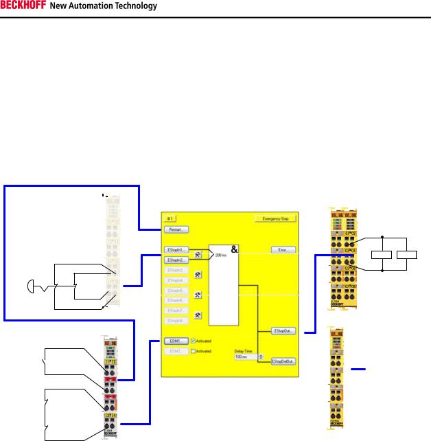
2.1 ESTOP function variant 1 (Category 3, PL d)
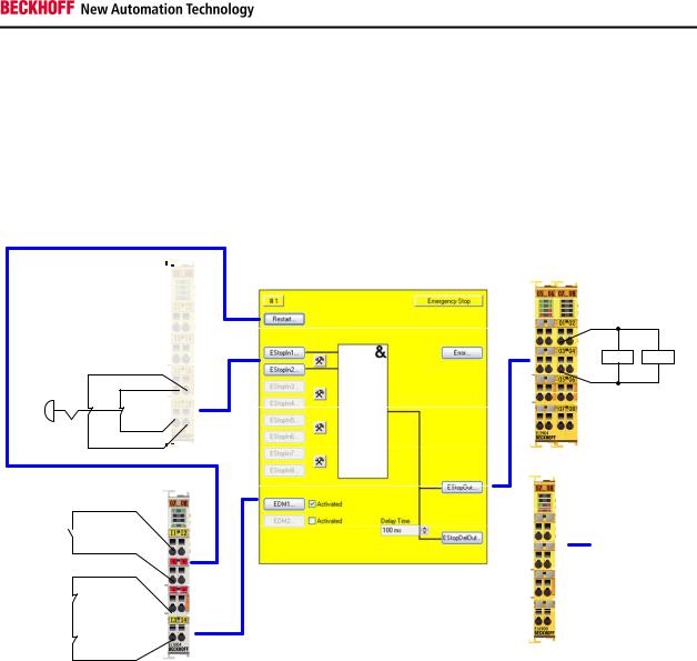
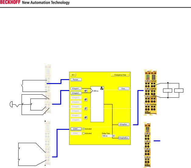
The emergency stop button is connected via two break contacts to an EL1904 safe input terminal. The testing and monitoring of the discrepancy of the two signals are activated. The restart and the feedback signal are wired to standard terminals and are transferred to TwinSAFE via standard PLC. The contactors K1 and K2 are connected in parallel to the safe output. Current measurement and testing of the output are active for this circuit.
2.1.1Parameters of the safe input and output terminals
EL1904
Parameter |
Value |
Sensor test channel 1 active |
Yes |
|
|
Sensor test channel 2 active |
Yes |
|
|
Sensor test channel 3 active |
Yes |
|
|
Sensor test channel 4 active |
Yes |
|
|
Logic channel 1 and 2 |
Single Logic |
|
|
Logic channel 3 and 4 |
Single Logic |
|
|
EL2904 |
|
Parameter |
Value |
Current measurement active |
Yes |
|
|
Output test pulses active |
Yes |
|
|
Application Guide TwinSAFE |
7 |
Circuit examples
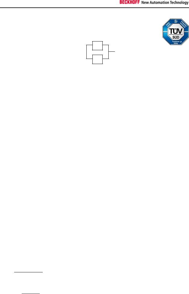
2.1.2Block formation and safety loops
2.1.2.1Block 1
K1
|
S1 |
|
EL1904 |
|
EL6900 |
|
EL2904 |
|
|
|
|
|
|
||||
|
|
|
|
|
|
|
|
|
K2
2.1.3 |
Calculation |
|
2.1.3.1 PFH / MTTFd /B10d – values |
|
|
|
|
|
Component |
Value |
|
EL1904 – PFH |
1.11E-09 |
|
|
|
|
EL2904 – PFH |
1.25E-09 |
|
|
|
|
EL6900 – PFH |
1.03E-09 |
|
|
|
|
S1 – B10d |
100,000 |
|
|
|
|
S2 – B10d |
10,000,000 |
|
|
|
|
K1 – B10d |
1,300,000 |
|
K2 – B10d |
1,300,000 |
|
|
|
|
Days of operation (dop) |
230 |
|
|
|
|
Hours of operation / day (hop) |
16 |
|
Cycle time (minutes) (Tcycle) |
10080 (1x per week) (7 days, 24 hours) |
|
|
|
|
Lifetime (T1) |
20 years = 175200 hours |
|
|
|
|
2.1.3.2 |
Diagnostic Coverage DC |
|
|
|
|
Component |
Value |
|
S1 with testing/plausibility |
DCavg=99% |
|
K1/K2 with testing and EDM (actuation 1x per week) |
DCavg=60% |
|
|
|
|
K1/K2 with testing and EDM (actuation 1x per shift) |
DCavg=90% |
|
|
|
|
2.1.3.3Calculation for block 1
Calculation of the PFH and MTTFd values from the B10d values:
From:
60 |
|
|
|
|
|
and:
100.1
8 |
Application Guide TwinSAFE |
Circuit examples
Inserting the values, this produces:
S1:
|
|
230 16 60 |
|
21.90 |
|||||
|
|
|
|||||||
|
|
|
|
10080 |
|
|
|
|
|
|
|
|
|
|
|
|
|
||
|
|
|
100000 |
|
|
|
45662.1y 399999120h |
||
|
|
|
|
|
|
||||
|
|
|
0.1 21.90 |
|
|||||
|
|
|
|
|
|||||
K1/K2: |
|
|
|
|
|
|
|
||
|
|
230 16 60 |
|
21.90 |
|||||
|
|
||||||||
|
|
|
|
10080 |
|
|
|
|
|
|
|
|
|
|
|
|
|
||
|
|
|
1300000 |
|
|
593607.3y 5199997320h |
|||
|
|
|
|
|
|
||||
|
|
|
0.1 21.90 |
|
|||||
|
|
|
|
|
|||||
and the assumption that S1, K1 and K2 are in each case single-channel:
1
results in a
! " 0.1 #1 $ %&' 1 $ DC10 MTTF-
S1:
1 $ 0.99
! " 45662.1 8760 2.50E $ 11
K1/K2: Actuation 1x per week
1 $ 0.60
! " 593607.3 8760 7.69E $ 11
K1/K2: Actuation 1x per shift
1 $ 0.90
! " 593607.3 8760 1.92E $ 11
The following assumptions have to be made now:
Safety switch S1: According to BIA report 2/2008, error exclusion up to 100,000 cycles is possible, provided the manufacturer has confirmed this. If no confirmation exists, S1 is included in the calculation as follows.
Relays K1 and K2 are both connected to the safety function. The non-functioning of a relay does not lead to a dangerous situation, but it is discovered by the feedback signal. Furthermore, the B10d values for K1 and K2 are identical.
There is a coupling coefficient between the components that are connected via two channels. Examples are temperature, EMC, voltage peaks or signals between these components. This is assumed to be the worst-case estimation, where ß =10%. EN 62061 contains a table with which this ß-factor can be precisely determined. Further, it is assumed that all usual measures have been taken to prevent both channels failing unsafely at the same time due to an error (e.g. overcurrent through relay contacts, over temperature in the control cabinet).
Application Guide TwinSAFE |
9 |

Circuit examples
This produces for the calculation of the PFH value for block 1:
PFHtot= PFH(S1) + PFH(EL1904) + PFH(EL6900) + PFH(EL2904) + β* (PFH(K1)+
PFH(K2))/2 + PFH(S2) + PFH(EL1904)
Since the portion (PFH(K1)* PFH(K2))*T1 is smaller than the rest by the power of ten, it is neglected in this and all further calculations for the purpose of simplification.
to:
PFHtot= 2.50E-11 + 1.11E-09 + 1.03E-09 + 1.25E-09 + 10% * (7.96E-11+7.96E-11)/2 =
3.42E-09
in the case of actuation 1x per week
or
PFHtot= 2.50E-11+1.11E-09 + 1.03E-09 + 1.25E-09 + 10% * (1.92E-11+1.92E-11)/2=
3.42E-09
in the case of actuation 1x per shift
The MTTFd value for block 1 (based on the same assumption) is calculated with:
1 |
= |
1 |
|
|
|
|
|
|
|
|
|
|
||
= < |
|
|
|
|
|
|
|
|
|
|
||||
; ; |
|
|
= |
|
|
|
|
|
|
|
||||
|
>?@ |
|
|
|
|
|
|
|
|
|
|
|
|
|
as: |
|
|
|
|
|
|
|
|
|
|
|
|
|
|
1 |
= |
|
1 |
|
|
|
+ |
1 |
+ |
1 |
+ |
1 |
||
; ; |
|
(A1) |
|
(BC1904) |
(BC6900) |
(2904) |
||||||||
|
+ |
|
|
1 |
|
|
|
|
|
|
|
|
||
|
( (D1)) |
|
|
|
|
|
||||||||
with:
(S1) = 10 (A1) 0.1
(K1) = 10 (D1) 0.1
If only PFH values are available for EL1904 and EL6900, the following estimation applies:
(ELxxxx) = (1 $ %&(BCFFF)) ! "(BCFFF)
Hence:
(EL1904) = |
G1 $ %&(BC1904)H |
= |
(1 $ 0.99) |
= |
0.01 |
|
|
= 1028.8y |
||||
! "(BC1904) |
1.11E $ 09 |
@ |
8760IJ |
|
9.72E $ 06 |
@ |
|
|||||
J |
||||||||||||
I |
||||||||||||
10 |
|
|
|
|
|
|
Application Guide TwinSAFE |
|||||
Circuit examples
#EL6900' |
G1 |
$ %BC6900'H |
|
|
#1 $ 0.99' |
|
|
0.01 |
|
|
|
1108.6y |
||||||||||||||||||||||||||
|
|
|
|
|
|
|
|
|
|
|
|
|
|
|
|
|
|
|
|
|
|
|
|
|||||||||||||||
|
|
|
|
|
|
|
|
|
|
! "#BC6900' |
|
1.03E $ 09 |
@ |
8760IJ |
|
|
9.02E $ 06 |
@ |
|
|||||||||||||||||||
|
|
|
|
|
|
|
|
|
|
|
|
|
|
J |
|
|||||||||||||||||||||||
|
|
|
|
|
|
|
|
|
|
|
|
I |
|
|||||||||||||||||||||||||
#EL2904' |
G1 $ %BC2904'H |
|
|
#1 $ 0.99' |
|
|
0.01 |
|
|
913.2y |
||||||||||||||||||||||||||||
|
|
|
|
|
|
|
|
|
|
|
|
|
|
|
|
|
|
|
|
|
|
|||||||||||||||||
|
|
|
|
|
|
|
|
|
|
! "#BC2904' |
|
|
|
1.25E $ 09 |
@ |
8760IJ |
|
1.1E $ 05 |
@ |
|
|
|
||||||||||||||||
|
|
|
|
|
|
|
|
|
|
|
|
|
|
|
J |
|
|
|
||||||||||||||||||||
|
|
|
|
|
|
|
|
|
|
|
|
|
|
I |
|
|
|
|||||||||||||||||||||
MTTFd tot= |
|
L |
R |
|
|
L |
R |
L |
|
R |
L |
|
R |
|
|
L |
|
|
333.98X |
|
|
|
|
|
|
|
||||||||||||
|
|
|
|
|
|
|
|
|
|
|
|
|
|
@ |
|
|
|
|
|
|
|
|
|
|
|
|
|
|
|
|
|
|
|
|
|
|
|
|
|
|
|
|
|
|
|
|
|
|
|
|
|
|
|
|
|
|
|
|
|
|
|
|
|
|
|
|
|
|
|
|
|
|
|
|
|
|
|
|
|
|
MNOOP.LQ |
|
|
LSPT.TQ |
LLST.OQ |
ULV.PQ |
NUVOSW.VQ |
|
|
|
|
|
|
|
||||||||||||||||||||||
DCavg= |
|
UU% |
R UU% R UU% R UU% R |
|
OS% |
R |
OS% |
|
98.96% |
|
|
|
|
|
|
|
|
|
|
|
||||||||||||||||||
|
|
|
|
|
|
|
|
|
R |
L R |
|
|
|
|
|
|
|
|
|
|
|
|
|
|
|
|
|
|
||||||||||
|
L |
R L |
|
R |
|
|
L |
|
|
L |
R |
|
L |
|
|
|
|
|
|
|
|
|
|
|
|
|||||||||||||
|
|
MNOOP.L LSPT.T LLST.O ULV.P NUVOSW.V NUVOSW.V |
|
|
|
|
|
|
|
|
|
|
|
|
|
|
||||||||||||||||||||||
|
|
|
|
|
|
|
|
|
|
|
|
|
|
|
|
|
|
|
|
|
|
|
|
|
|
|
|
|
|
|||||||||
|
|
MNOOP.L |
|
LSPT.T |
LLST.O |
|
|
ULV.P |
NUVOSW.V |
|
|
NUVOSW.V |
|
|
|
|
|
|
|
|
|
|
|
|
|
|
||||||||||||
or: |
|
|
|
|
|
|
|
|
|
|
|
|
|
|
|
|
|
|
|
|
|
|
|
|
|
|
|
|
|
|
|
|
|
|
|
|
|
|
DCavg= |
|
UU% |
R UU% R UU% R UU% R |
|
US% |
R |
US% |
|
98.99% |
|
|
|
|
|
|
|
|
|
|
|
||||||||||||||||||
|
|
|
|
|
|
|
|
|
R |
L R |
|
|
|
|
|
|
|
|
|
|
|
|
|
|
|
|
|
|
||||||||||
|
L |
R L |
|
R |
|
|
L |
|
|
L |
R |
|
L |
|
|
|
|
|
|
|
|
|
|
|
|
|||||||||||||
|
|
MNOOP.L LSPT.T LLST.O ULV.P NUVOSW.V NUVOSW.V |
|
|
|
|
|
|
|
|
|
|
|
|
|
|
||||||||||||||||||||||
|
|
|
|
|
|
|
|
|
|
|
|
|
|
|
|
|
|
|
|
|
|
|
|
|
|
|
|
|
|
|||||||||
|
|
MNOOP.L |
|
LSPT.T |
LLST.O |
|
|
ULV.P |
NUVOSW.V |
|
|
NUVOSW.V |
|
|
|
|
|
|
|
|
|
|
|
|
|
|
||||||||||||
Measures for attaining category 3!
This structure is possible up to category 3 at the most, since an error in the feedback CAUTION path of the relays may be undiscovered. In order to attain category 3, all rising and
falling edges must be evaluated together with the time dependence in the controller for the feedback expectation!
Implement a restart lock in the machine!
The restart lock is NOT part of the safety chain and must be implemented in the CAUTION machine!
|
MTTFd |
|
Designation for each channel |
|
Range for each channel |
low |
|
3 years ≤ MTTFd < 10 years |
medium |
|
10 years ≤ MTTFd < 30 years |
high |
|
30 years ≤ MTTFd ≤ 100 years |
|
|
|
|
DCavg |
|
Designation |
|
Range |
none |
|
DC < 60 % |
low |
|
60 % ≤ DC < 90 % |
medium |
|
90 % ≤ DC < 99 % |
high |
|
99 % ≤ DC |
Application Guide TwinSAFE |
11 |
Circuit examples
Category |
B |
1 |
2 |
2 |
3 |
3 |
4 |
|
|
|
|
|
|
|
|
DC |
none |
none |
low |
medium |
low |
medium |
high |
MTTFd |
|
|
|
|
|
|
|
low |
a |
- |
a |
b |
b |
c |
- |
|
|
|
|
|
|
|
|
medium |
b |
- |
b |
c |
c |
d |
- |
|
|
|
|
|
|
|
|
high |
- |
c |
c |
d |
d |
d |
e |
|
|
|
|
|
|
|
|
12 |
Application Guide TwinSAFE |
Circuit examples
2.2 ESTOP function variant 2 (Category 3, PL d)
The emergency stop button is connected via two break contacts to an EL1904 safe input terminal. The testing of the two signals is activated. The signals are not tested for discrepancy. The restart and the feedback signal are wired to standard terminals and are transferred to TwinSAFE via the standard PLC. The contactors K1 and K2 are connected in parallel to the safe output. Current measurement and testing of the output are active for this circuit.
2.2.1Parameters of the safe input and output terminals
EL1904
Parameter |
Value |
Sensor test channel 1 active |
Yes |
|
|
Sensor test channel 2 active |
Yes |
|
|
Sensor test channel 3 active |
Yes |
|
|
Sensor test channel 4 active |
Yes |
|
|
Logic channel 1 and 2 |
Single Logic |
|
|
Logic channel 3 and 4 |
Single Logic |
|
|
EL2904 |
|
Parameter |
Value |
Current measurement active |
Yes |
|
|
Output test pulses active |
Yes |
|
|
Application Guide TwinSAFE |
13 |

Circuit examples
2.2.2Block formation and safety loops
2.2.2.1Block 1
K1
|
S1 |
|
EL1904 |
|
EL6900 |
|
EL6900 |
|
|
|
|
|
|
||||
|
|
|
|
|
|
|
|
|
K2
2.2.3 |
Calculation |
|
2.2.3.1 PFH / MTTFd /B10d – values |
|
|
|
|
|
Component |
Value |
|
EL1904 – PFH |
1.11E-09 |
|
|
|
|
EL2904 – PFH |
1.25E-09 |
|
|
|
|
EL6900 – PFH |
1.03E-09 |
|
|
|
|
S1 – B10d |
100,000 |
|
|
|
|
S2 – B10d |
10,000,000 |
|
|
|
|
K1 – B10d |
1,300,000 |
|
K2 – B10d |
1,300,000 |
|
|
|
|
Days of operation (dop) |
230 |
|
|
|
|
Hours of operation / day (hop) |
16 |
|
Cycle time (minutes) (Tcycle) |
10080 (1x per week) |
|
|
|
|
Lifetime (T1) |
20 years = 175200 hours |
|
|
|
|
2.2.3.2 |
Diagnostic Coverage DC |
|
|
|
|
Component |
Value |
|
S1 with testing / without plausibility |
DCavg=90% |
|
K1/K2 with testing and EDM (actuation 1x per |
DCavg=60% |
|
week and indirect feedback) |
|
|
|
|
|
K1/K2 with testing and EDM (actuation 1x per shift |
DCavg=90% |
|
and direct feedback) |
|
|
|
|
|
2.2.3.3Calculation for block 1
Calculation of the PFH and MTTFd values from the B10d values:
From:
60 |
|
|
|
|
|
|
|
|
and: |
|
|
14 |
|
Application Guide TwinSAFE |

Circuit examples
|
|
|
10 |
|
|
|
|
|
||
0.1 |
|
|
|
|
|
|||||
|
|
|
|
|
|
|
|
|
||
Insertion of the values results in: |
||||||||||
S1: |
|
|
|
|
|
|
|
|
|
|
|
|
230 16 60 |
|
21.90 |
||||||
|
|
|||||||||
|
|
|
|
10080 |
|
|
|
|
|
|
|
|
|
|
|
|
|
|
|
||
|
|
|
100000 |
|
|
|
45662.1y 399999120h |
|||
|
|
|
|
|
|
|
||||
|
|
|
0.1 21.90 |
|
||||||
|
|
|
|
|
||||||
K1/K2: |
|
|
|
|
|
|
|
|
||
|
|
230 16 60 |
|
21.90 |
||||||
|
|
|||||||||
|
|
|
|
10080 |
|
|
|
|
|
|
|
|
|
|
|
|
|
|
|
||
|
|
|
1300000 |
|
|
593607.3y 5199997320h |
||||
|
|
|
|
|
|
|
||||
|
|
|
0.1 21.90 |
|
||||||
|
|
|
|
|
||||||
and the assumption that S1, K1 and K2 are in each case single-channel:
1
results in a
! " 0.1 #1 $ %&' 1 $ DC10 MTTF-
S1:
1 $ 0.90
! " 45662.1 8760 2.50E $ 10
K1/K2: actuation 1x per week
1 $ 0.60
! " 593607.3 8760 7.69E $ 11
K1/K2: actuation 1x per shift
1 $ 0.90
! " 593607.3 8760 1.92E $ 11
The following assumptions have to be made now:
Safety switch S1: According to BIA report 2/2008, error exclusion to up to 100,000 cycles is possible, provided the manufacturer has confirmed this. If no confirmation exists, S1 is included in the calculation as follows.
Relays K1 and K2 are both connected to the safety function. The non-functioning of a relay does not lead to a dangerous situation, but it is discovered by the feedback signal. Furthermore, the B10d values for K1
Application Guide TwinSAFE |
15 |

Circuit examples
and K2 are identical.
There is a coupling coefficient between the components that are connected via two channels. Examples are temperature, EMC, voltage peaks or signals between these components. This is assumed to be the worst-case estimation, where ß =10%. EN 62061 contains a table with which this ß-factor can be precisely determined. Further, it is assumed that all usual measures have been taken to prevent both channels failing unsafely at the same time due to an error (e.g. overcurrent through relay contacts, over temperature in the control cabinet).
This produces for the calculation of the PFH value for block 1:
PFHtot= PFH(S1) + PFH(EL1904) + PFH(EL6900) + PFH(EL2904) + β* (PFH(K1)+
PFH(K2))/2
to:
PFHtot= 2.50E-10 + 1.11E-09 + 1.03E-09 + 1.25E-09 + 10%* (7.96E-11+7.96E-11)/2 =
3.65E-09
in the case of actuation 1x per week and indirect feedback
or
PFHtot= 2.50E-10+1.11E-09 + 1.03E-09 + 1.25E-09 + 10%* (1.92E-11+1.92E-11)/2 =
3.65E-09
in the case of actuation 1x per shift and direct feedback
The MTTFd value for block 1 (based on the same assumption) is calculated with:
1 |
= |
1 |
|
|
|
|
|
|
|
|
|
|
||
= < |
|
|
|
|
|
|
|
|
|
|
||||
; ; |
|
|
= |
|
|
|
|
|
|
|
||||
|
>?@ |
|
|
|
|
|
|
|
|
|
|
|
|
|
as: |
|
|
1 |
|
|
|
|
1 |
|
1 |
|
1 |
||
1 |
= |
|
|
|
|
+ |
+ |
+ |
||||||
; ; |
|
(A1) |
|
(BC1904) |
(BC6900) |
(2904) |
||||||||
|
+ |
|
|
1 |
|
|
|
|
|
|
|
|
||
|
( (D1)) |
|
|
|
|
|
||||||||
with:
(S1) = 10 (A1) 0.1
(K1) = 10 (D1) 0.1
If only PFH values are available for EL1904 and EL6900, the following estimation applies:
16 |
Application Guide TwinSAFE |
|
|
|
|
|
|
|
|
|
|
|
|
|
|
|
|
|
|
|
|
|
|
|
|
|
|
|
|
|
|
|
Circuit examples |
||||||
|
|
|
|
|
|
|
|
|
|
|
|
|
|
|
|
|
|
|
|
|
|
|
|
|
|
|
|
|
|
|
|
|
|
|
|
||
#ELxxxx' |
#1 $ %BCFFF'' |
|
|
|
|
|
|
|
|
|
|
|
|
|
|
|
|
|
|
|
|||||||||||||||||
|
|
|
|
|
|
|
|
|
|
|
|
|
|
|
|
|
|
|
|
|
|
|
|
|
|
||||||||||||
|
|
|
|
|
|
|
|
|
! "#BCFFF' |
|
|
|
|
|
|
|
|
|
|
|
|
|
|
|
|
|
|
|
|
|
|||||||
|
|
|
|
|
|
|
|
|
|
|
|
|
|
|
|
|
|
|
|
|
|
|
|
|
|
|
|
|
|
||||||||
Hence: |
|
|
|
|
|
|
|
|
|
|
|
|
|
|
|
|
|
|
|
|
|
|
|
|
|
|
|
|
|
|
|
|
|
|
|
|
|
#EL1904' |
G1 $ %BC1904'H |
|
#1 $ 0.99' |
|
|
0.01 |
|
|
|
|
|
|
1028.8y |
||||||||||||||||||||||||
|
|
|
|
|
|
|
|
|
|
|
|
|
|
|
|
|
|
|
|
|
|
|
|
||||||||||||||
|
|
|
|
|
|
|
|
|
! "#BC1904' |
1.11E $ 09 |
@ |
|
8760IJ |
|
9.72E $ 06 |
@ |
|
|
|
||||||||||||||||||
|
|
|
|
|
|
|
|
|
|
|
J |
|
|||||||||||||||||||||||||
|
|
|
|
|
|
|
|
|
I |
|
|||||||||||||||||||||||||||
#EL6900' |
#1 $ %BC6900'' |
|
#1 $ 0.99' |
|
|
0.01 |
|
|
|
|
|
|
1108.6y |
||||||||||||||||||||||||
|
|
|
|
|
|
|
|
|
|
|
|
|
|
|
|
|
|
|
|
|
|
|
|
||||||||||||||
|
|
|
|
|
|
|
|
|
! "#BC6900' |
|
|
|
1.03E $ 09 |
@ |
8760IJ |
|
9.02E $ 06 |
@ |
|
|
|
||||||||||||||||
|
|
|
|
|
|
|
|
|
|
|
|
|
J |
|
|||||||||||||||||||||||
|
|
|
|
|
|
|
|
|
|
|
|
I |
|
||||||||||||||||||||||||
#EL2904' |
#1 $ %BC2904'' |
|
#1 $ 0.99' |
|
|
0.01 |
|
|
|
913.2y |
|||||||||||||||||||||||||||
|
|
|
|
|
|
|
|
|
|
|
|
|
|
|
|
|
|
|
|
|
|||||||||||||||||
|
|
|
|
|
|
|
|
|
! "#BC2904' |
|
|
|
1.25E $ 09 |
@ |
8760IJ |
|
1.1E $ 05 |
@ |
|
|
|
|
|
||||||||||||||
|
|
|
|
|
|
|
|
|
|
|
|
|
J |
|
|||||||||||||||||||||||
|
|
|
|
|
|
|
|
|
|
|
|
I |
|
||||||||||||||||||||||||
MTTFd tot= |
|
L |
R |
|
L |
R |
L |
|
R |
L |
|
R L |
|
333.98X |
|
|
|
|
|
|
|
|
|
||||||||||||||
|
|
|
|
|
|
|
|
|
|
|
|
@ |
|
|
|
|
|
|
|
|
|
|
|
|
|
|
|
|
|
|
|
|
|
|
|
|
|
|
|
|
|
|
|
|
|
|
|
|
|
|
|
|
|
|
|
|
|
|
|
|
|
|
|
|
|
|
|
|
|
|
|
|
|
|
|
|
|
MNOOP.LQ |
|
|
LSPT.TQ |
LLST.OQ |
ULV.PQ |
NUVOSW.VQ |
|
|
|
|
|
|
|
|
|
||||||||||||||||||||
DCavg= |
US% |
R UU% R UU% R UU% R |
|
OS% |
R |
OS% |
98.89% |
|
|
|
|
|
|
|
|
|
|
|
|
||||||||||||||||||
|
|
|
|
|
|
|
R |
L R |
|
|
|
|
|
|
|
|
|
|
|
|
|
|
|
|
|
|
|
||||||||||
L |
R L |
|
R |
|
L |
|
|
L |
R |
|
|
L |
|
|
|
|
|
|
|
|
|
|
|
|
|||||||||||||
|
MNOOP.L LSPT.T LLST.O ULV.P NUVOSW.V NUVOSW.V |
|
|
|
|
|
|
|
|
|
|
|
|
|
|
|
|
||||||||||||||||||||
|
|
|
|
|
|
|
|
|
|
|
|
|
|
|
|
|
|
|
|
|
|
|
|
|
|
|
|
|
|
||||||||
|
MNOOP.L |
|
LSPT.T |
LLST.O |
|
|
ULV.P |
NUVOSW.V |
|
|
NUVOSW.V |
|
|
|
|
|
|
|
|
|
|
|
|
|
|
|
|
||||||||||
or: |
|
|
|
|
|
|
|
|
|
|
|
|
|
|
|
|
|
|
|
|
|
|
|
|
|
|
|
|
|
|
|
|
|
|
|
|
|
DCavg= |
US% |
R UU% R UU% R UU% R |
|
US% |
R |
US% |
98.92% |
|
|
|
|
|
|
|
|
|
|
|
|
||||||||||||||||||
|
|
|
|
|
|
|
R |
L R |
|
|
|
|
|
|
|
|
|
|
|
|
|
|
|
|
|
|
|
||||||||||
L |
R L |
|
R |
|
L |
|
|
L |
R |
|
|
L |
|
|
|
|
|
|
|
|
|
|
|
|
|||||||||||||
|
MNOOP.L LSPT.T LLST.O ULV.P NUVOSW.V NUVOSW.V |
|
|
|
|
|
|
|
|
|
|
|
|
|
|
|
|
||||||||||||||||||||
|
|
|
|
|
|
|
|
|
|
|
|
|
|
|
|
|
|
|
|
|
|
|
|
|
|
|
|
|
|
||||||||
|
MNOOP.L |
|
LSPT.T |
LLST.O |
|
|
ULV.P |
NUVOSW.V |
|
|
NUVOSW.V |
|
|
|
|
|
|
|
|
|
|
|
|
|
|
|
|
||||||||||
Measures for attaining category 3!
This structure is possible only up to category 3 at the most on account of a possible CAUTION sleeping error. In order to attain category 3, all rising and falling edges must be
evaluated together with the time dependence in the controller for the feedback expectation!
Implement a restart lock in the machine!
The restart lock is NOT part of the safety chain and must be implemented in the CAUTION machine!
|
MTTFd |
|
Designation for each channel |
|
Range for each channel |
low |
|
3 years ≤ MTTFd < 10 years |
medium |
|
10 years ≤ MTTFd < 30 years |
high |
|
30 years ≤ MTTFd ≤ 100 years |
Application Guide TwinSAFE |
17 |
Circuit examples
|
Designation |
|
DCavg |
|
Range |
|
||||
|
|
|
|
|
|
|||||
|
|
none |
|
|
|
DC < 60 % |
|
|||
|
|
low |
|
|
|
60 % ≤ DC < 90 % |
|
|||
|
medium |
|
|
|
90 % ≤ DC < 99 % |
|
||||
|
|
high |
|
|
|
99 % ≤ DC |
|
|||
|
|
|
|
|
|
|
|
|
|
|
Category |
B |
|
1 |
2 |
|
2 |
3 |
|
3 |
4 |
|
|
|
|
|
|
|
|
|
|
|
DC |
none |
|
none |
low |
|
medium |
low |
|
medium |
high |
MTTFd |
|
|
|
|
|
|
|
|
|
|
low |
a |
|
- |
a |
|
b |
b |
|
c |
- |
|
|
|
|
|
|
|
|
|
|
|
medium |
b |
|
- |
b |
|
c |
c |
|
d |
- |
|
|
|
|
|
|
|
|
|
|
|
high |
- |
|
c |
c |
|
d |
d |
|
d |
e |
|
|
|
|
|
|
|
|
|
|
|
18 |
Application Guide TwinSAFE |

Circuit examples
2.3 ESTOP function variant 3 (Category 4, PL e)
The emergency stop button is connected via two break contacts to an EL1904 safe input terminal. The testing of the two signals is activated. These signals are checked for discrepancy. The restart and the feedback signal are wired to standard terminals and are transferred to TwinSAFE via the standard PLC. Furthermore, the output of the ESTOP function block and the feedback signal are wired to an EDM block. This checks that the feedback signal assumes the opposing state of the ESTOP output within the set time.
The contactors K1 and K2 are connected in parallel to the safe output. Current measurement and testing of the output are active for this circuit.
2.3.1Parameters of the safe input and output terminals
EL1904
Parameter |
Value |
Sensor test channel 1 active |
Yes |
Sensor test channel 2 active |
Yes |
Sensor test channel 3 active |
Yes |
Sensor test channel 4 active |
Yes |
Logic channel 1 and 2 |
Single Logic |
Logic channel 3 and 4 |
Single Logic |
Application Guide TwinSAFE |
19 |

Circuit examples
EL2904
Parameter |
Value |
Current measurement active |
Yes |
|
|
Output test pulses active |
Yes |
|
|
2.3.2Block formation and safety loops
2.3.2.1Block 1
|
|
|
|
|
|
|
|
|
|
K1 |
|
|
|
|
|
|
|
|
|
|
|
|
|
|
S1 |
|
EL1904 |
|
EL6900 |
|
EL2904 |
|
|
|
|
|
|
|
|
|
|
|
|
||||
|
|
|
|
|
|
|
|
||||
|
|
|
|
|
|
|
|
|
|
K2 |
|
|
|
|
|
|
|
|
|
|
|
|
|
|
|
|
|
|
|
|
|
|
|
|
|
|
|
|
|
|
|
|
|
|
|
|
|
2.3.3 |
Calculation |
|
2.3.3.1 PFH / MTTFd /B10d – values |
|
|
|
|
|
Component |
Value |
|
EL1904 – PFH |
1.11E-09 |
|
|
|
|
EL2904 – PFH |
1.25E-09 |
|
|
|
|
EL6900 – PFH |
1.03E-09 |
|
|
|
|
S1 – B10d |
100,000 |
|
|
|
|
S2 – B10d |
10,000,000 |
|
|
|
|
K1 – B10d |
1,300,000 |
|
K2 – B10d |
1,300,000 |
|
|
|
|
Days of operation (dop) |
230 |
|
|
|
|
Hours of operation / day (hop) |
16 |
|
Cycle time (minutes) (Tcycle) |
10080 (1x per week) |
|
|
|
|
Lifetime (T1) |
20 years = 175200 hours |
|
|
|
|
2.3.3.2 |
Diagnostic Coverage DC |
|
|
|
|
Component |
Value |
|
S1 with testing/plausibility |
DCavg=99% |
|
K1/K2 with testing and EDM (actuation 1x per |
DCavg=90% |
|
week and indirect feedback) |
|
|
|
|
|
K1/K2 with testing and EDM (actuation 1x per shift |
DCavg=99% |
|
and direct feedback) |
|
|
|
|
|
2.3.3.3Calculation for block 1
Calculation of the PFH and MTTFd values from the B10d values:
20 |
Application Guide TwinSAFE |

Circuit examples
From: |
|
|
|
|
|
|
|
|
||
60 |
|
|
|
|||||||
|
|
|
|
|
|
|
|
|
|
|
|
|
|
|
|
|
|
|
|
||
and: |
|
|
|
|
|
|
|
|
|
|
|
|
|
10 |
|
|
|
|
|
||
0.1 |
|
|
|
|
|
|||||
|
|
|
|
|
|
|
|
|
||
Inserting the values, this produces: |
||||||||||
S1: |
|
|
|
|
|
|
|
|
|
|
|
|
230 16 60 |
|
21.90 |
||||||
|
|
|||||||||
|
|
|
|
10080 |
|
|
|
|
|
|
|
|
|
|
|
|
|
|
|
||
|
|
|
100000 |
|
|
|
45662.1y 399999120h |
|||
|
|
|
|
|
|
|
||||
|
|
|
0.1 21.90 |
|
||||||
|
|
|
|
|
||||||
K1/K2: |
|
|
|
|
|
|
|
|
||
|
|
230 16 60 |
|
21.90 |
||||||
|
|
|||||||||
|
|
|
|
10080 |
|
|
|
|
|
|
|
|
|
|
|
|
|
|
|
||
|
|
|
1300000 |
|
|
593607.3y 5199997320h |
||||
|
|
|
|
|
|
|
||||
|
|
|
0.1 21.90 |
|
||||||
|
|
|
|
|
||||||
and the assumption that S1, K1 and K2 are in each case single-channel:
1
results in a
! " 0.1 #1 $ %&' 1 $ DC10 MTTF-
S1:
1 $ 0.99
! " 45662.1 8760 2.50E $ 11
K1/K2: actuation 1x per week
1 $ 0.90
! " 593607.3 8760 1.92E $ 11
K1/K2: actuation 1x per shift
1 $ 0.99
! " 593607.3 8760 1.92E $ 12
Application Guide TwinSAFE |
21 |

Circuit examples
The following assumptions have to be made now:
Safety switch S1: According to BIA report 2/2008, error exclusion to up to 100,000 cycles is possible, provided the manufacturer has confirmed this. If no confirmation exists, S1 is included in the calculation as follows.
Relays K1 and K2 are both connected to the safety function. The non-functioning of a relay does not lead to a dangerous situation, but it is discovered by the feedback signal. Furthermore, the B10d values for K1 and K2 are identical.
There is a coupling coefficient between the components that are connected via two channels. Examples are temperature, EMC, voltage peaks or signals between these components. This is assumed to be the worst-case estimation, where ß =10%. EN 62061 contains a table with which this ß-factor can be precisely determined. Further, it is assumed that all usual measures have been taken to prevent both channels failing unsafely at the same time due to an error (e.g. overcurrent through relay contacts, over temperature in the control cabinet).
This produces for the calculation of the PFH value for block 1:
PFHtot= PFH(S1) + PFH(EL1904) + PFH(EL6900) + PFH(EL2904) + β* (PFH(K1)+
PFH(K2))/2
to:
PFHtot= 2.50E-11+1.11E-09 + 1.03E-09 + 1.25E-09 + 10%* (1.92E-11+1.92E-11)/2 =
3.42E-09
in the case of actuation 1x per week and indirect feedback
or
PFHtot= 2.50E-11+1.11E-09 + 1.03E-09 + 1.25E-09 + 10%* (1.92E-11+1.92E-11)/2 =
3.42E-09
in the case of actuation 1x per shift and direct feedback
The MTTFd value for block 1 (based on the same assumption) is calculated with:
1 |
= |
1 |
|
|
|
|
|
|
|
|
|
|
||
= < |
|
|
|
|
|
|
|
|
|
|
||||
; ; |
|
|
= |
|
|
|
|
|
|
|
||||
|
>?@ |
|
|
|
|
|
|
|
|
|
|
|
|
|
as: |
|
|
1 |
|
|
|
|
1 |
|
1 |
|
1 |
||
1 |
= |
|
|
|
|
+ |
+ |
+ |
||||||
; ; |
|
(A1) |
|
(BC1904) |
(BC6900) |
(2904) |
||||||||
|
+ |
|
|
1 |
|
|
|
|
|
|
|
|
||
|
( (D1)) |
|
|
|
|
|
||||||||
with:
(S1) = 10 (A1) 0.1
22 |
Application Guide TwinSAFE |
Circuit examples
10 #D1'#K1' 0.1
If only PFH values are available for EL1904 and EL6900, the following estimation applies:
#1 $ %BCFFF''#ELxxxx' ! "#BCFFF'
Hence:
#EL1904' |
G1 $ %BC1904'H |
|
#1 $ 0.99' |
|
|
0.01 |
|
|
|
|
|
1028.8y |
||||||||||||||||||||||||
|
|
|
|
|
|
|
|
|
|
|
|
|
|
|
|
|
|
|
|
|
|
|
||||||||||||||
|
|
|
|
|
|
|
|
|
! "#BC1904' |
1.11E $ 09 |
@ |
|
8760IJ |
|
9.72E $ 06 |
@ |
|
|
|
|||||||||||||||||
|
|
|
|
|
|
|
|
|
|
|
J |
|
||||||||||||||||||||||||
|
|
|
|
|
|
|
|
|
I |
|
||||||||||||||||||||||||||
#EL6900' |
#1 $ %BC6900'' |
|
#1 $ 0.99' |
|
|
0.01 |
|
|
|
|
|
1108.6y |
||||||||||||||||||||||||
|
|
|
|
|
|
|
|
|
|
|
|
|
|
|
|
|
|
|
|
|
|
|
||||||||||||||
|
|
|
|
|
|
|
|
|
! "#BC6900' |
|
|
|
1.03E $ 09 |
@ |
8760IJ |
|
9.02E $ 06 |
@ |
|
|
|
|||||||||||||||
|
|
|
|
|
|
|
|
|
|
|
|
|
J |
|
||||||||||||||||||||||
|
|
|
|
|
|
|
|
|
|
|
|
I |
|
|||||||||||||||||||||||
#EL2904' |
#1 $ %BC2904'' |
|
#1 $ 0.99' |
|
|
0.01 |
|
|
913.2y |
|||||||||||||||||||||||||||
|
|
|
|
|
|
|
|
|
|
|
|
|
|
|
|
|
|
|
|
|||||||||||||||||
|
|
|
|
|
|
|
|
|
! "#BC2904' |
|
|
|
1.25E $ 09 |
@ |
8760IJ |
|
1.1E $ 05 |
@ |
|
|
|
|
|
|||||||||||||
|
|
|
|
|
|
|
|
|
|
|
|
|
J |
|
|
|
|
|
||||||||||||||||||
|
|
|
|
|
|
|
|
|
|
|
|
I |
|
|
|
|
|
|||||||||||||||||||
MTTFd tot= |
|
L |
R |
|
L |
R |
L |
|
R |
L |
|
R L |
|
333.98X |
|
|
|
|
|
|
|
|
||||||||||||||
|
|
|
|
|
|
|
|
|
|
|
|
@ |
|
|
|
|
|
|
|
|
|
|
|
|
|
|
|
|
|
|
|
|
|
|
|
|
|
|
|
|
|
|
|
|
|
|
|
|
|
|
|
|
|
|
|
|
|
|
|
|
|
|
|
|
|
|
|
|
|
|
|
|
|
|
|
MNOOP.LQ |
|
|
LSPT.TQ |
LLST.OQ |
ULV.PQ |
NUVOSW.VQ |
|
|
|
|
|
|
|
|
||||||||||||||||||||
DCavg= |
UU% |
R UU% R UU% R UU% R |
|
US% |
R |
US% |
98.99% |
|
|
|
|
|
|
|
|
|
|
|
||||||||||||||||||
|
|
|
|
|
|
|
R |
L R |
|
|
|
|
|
|
|
|
|
|
|
|
|
|
|
|
|
|
||||||||||
L |
R L |
|
R |
|
L |
|
|
L |
R |
|
|
L |
|
|
|
|
|
|
|
|
|
|
|
|||||||||||||
|
MNOOP.L LSPT.T LLST.O ULV.P NUVOSW.V NUVOSW.V |
|
|
|
|
|
|
|
|
|
|
|
|
|
|
|
||||||||||||||||||||
|
|
|
|
|
|
|
|
|
|
|
|
|
|
|
|
|
|
|
|
|
|
|
|
|
|
|
|
|
||||||||
|
MNOOP.L |
|
LSPT.T |
LLST.O |
|
|
ULV.P |
NUVOSW.V |
|
|
NUVOSW.V |
|
|
|
|
|
|
|
|
|
|
|
|
|
|
|
||||||||||
or: |
|
|
|
|
|
|
|
|
|
|
|
|
|
|
|
|
|
|
|
|
|
|
|
|
|
|
|
|
|
|
|
|
|
|
|
|
DCavg= |
UU% |
R UU% R UU% R UU% R |
|
UU% |
R |
UU% |
99.00% |
|
|
|
|
|
|
|
|
|
|
|
||||||||||||||||||
|
|
|
|
|
|
|
R |
L R |
|
|
|
|
|
|
|
|
|
|
|
|
|
|
|
|
|
|
||||||||||
L |
R L |
|
R |
|
L |
|
|
L |
R |
|
|
L |
|
|
|
|
|
|
|
|
|
|
|
|||||||||||||
|
MNOOP.L LSPT.T LLST.O ULV.P NUVOSW.V NUVOSW.V |
|
|
|
|
|
|
|
|
|
|
|
|
|
|
|
||||||||||||||||||||
|
|
|
|
|
|
|
|
|
|
|
|
|
|
|
|
|
|
|
|
|
|
|
|
|
|
|
|
|
||||||||
|
MNOOP.L |
|
LSPT.T |
LLST.O |
|
|
ULV.P |
NUVOSW.V |
|
|
NUVOSW.V |
|
|
|
|
|
|
|
|
|
|
|
|
|
|
|
||||||||||
Measures for attaining category 4!
This structure is possible up to category 4 at the most. In order to attain category 4, all CAUTION rising and falling edges must be evaluated together with the time dependence in the
controller for the feedback expectation!
Implement a restart lock in the machine!
The restart lock is NOT part of the safety chain and must be implemented in the CAUTION machine!
Application Guide TwinSAFE |
23 |
Circuit examples
|
|
MTTFd |
||
|
Designation for each channel |
|
|
Range for each channel |
|
low |
|
|
3 years ≤ MTTFd < 10 years |
|
medium |
|
|
10 years ≤ MTTFd < 30 years |
|
high |
|
|
30 years ≤ MTTFd ≤ 100 years |
|
|
|
|
|
|
|
DCavg |
||
|
Designation |
|
|
Range |
|
none |
|
|
DC < 60 % |
|
low |
|
|
60 % ≤ DC < 90 % |
|
medium |
|
|
90 % ≤ DC < 99 % |
|
high |
|
|
99 % ≤ DC |
For practical usability, the number of the ranges was limited to four. An accuracy of 5% is assumed for the limit values shown in this table.
Category |
B |
1 |
2 |
2 |
3 |
3 |
4 |
|
|
|
|
|
|
|
|
DC |
none |
none |
low |
medium |
low |
medium |
high |
MTTFd |
|
|
|
|
|
|
|
low |
a |
- |
a |
b |
b |
c |
- |
|
|
|
|
|
|
|
|
medium |
b |
- |
b |
c |
c |
d |
- |
|
|
|
|
|
|
|
|
high |
- |
c |
c |
d |
d |
d |
e |
|
|
|
|
|
|
|
|
24 |
Application Guide TwinSAFE |
Circuit examples
2.4 ESTOP function variant 4 (Category 4, PL e)
The emergency stop button with two break contacts, the restart and the feedback loop are connected to safe channels of an EL1904 input terminal. The testing of the signals is activated. The two emergency stop signals are tested for discrepancy. The contactors K1 and K2 are connected in parallel to the safe output. Current measurement and testing of the output are active for this circuit.
2.4.1Parameters of the safe input and output terminals
EL1904 (applies to all EL1904 used)
Parameter |
Value |
Sensor test channel 1 active |
Yes |
|
|
Sensor test channel 2 active |
Yes |
|
|
Sensor test channel 3 active |
Yes |
|
|
Sensor test channel 4 active |
Yes |
|
|
Logic channel 1 and 2 |
Single Logic |
|
|
Logic channel 3 and 4 |
Single Logic |
|
|
EL2904 |
|
Parameter |
Value |
Current measurement active |
Yes |
|
|
Output test pulses active |
Yes |
|
|
Application Guide TwinSAFE |
25 |

Circuit examples
2.4.2Block formation and safety loops
2.4.2.1Block 1
|
|
|
|
|
|
|
|
|
|
K1 |
|
|
|
|
|
|
|
|
|
|
|
|
|
|
|
|
|
|
|
|
|
|
S1 |
|
EL1904 |
|
EL6900 |
|
EL2904 |
|
|
|
|
|
S2 |
|
EL1904 |
|
|
|
|
|
|
|
|
|
|
||||||
|
|
|
|
|
|
|
|
|
|
||||||
|
|
|
|
|
|
|
|
|
|
K2 |
|
|
|
|
|
|
|
|
|
|
|
|
|
|
|
|
|
|
|
|
|
|
|
|
|
|
|
|
|
|
|
|
|
|
|
|
|
|
|
|
|
|
|
|
|
|
|
|
|
|
|
|
|
2.4.3 |
Calculation |
|
2.4.3.1 PFH / MTTFd /B10d – values |
|
|
|
|
|
Component |
Value |
|
EL1904 – PFH |
1.11E-09 |
|
|
|
|
EL2904 – PFH |
1.25E-09 |
|
|
|
|
EL6900 – PFH |
1.03E-09 |
|
|
|
|
S1 – B10d |
100,000 |
|
|
|
|
S2 – B10d |
10,000,000 |
|
|
|
|
K1 – B10d |
1,300,000 |
|
K2 – B10d |
1,300,000 |
|
|
|
|
Days of operation (dop) |
230 |
|
|
|
|
Hours of operation / day (hop) |
16 |
|
Cycle time (minutes) (Tcycle) |
10080 (1x per week) |
|
|
|
|
Lifetime (T1) |
20 years = 175200 hours |
|
|
|
|
2.4.3.2 |
Diagnostic Coverage DC |
|
|
|
|
Component |
Value |
|
S1 with testing/plausibility |
DCavg=99% |
|
|
|
|
S2 with plausibility |
DCavg=90% |
|
|
|
|
K1/K2 with testing and EDM (actuation 1x per |
DCavg=90% |
|
week and indirect feedback) |
|
|
|
|
|
K1/K2 with testing and EDM (actuation 1x per shift |
DCavg=99% |
|
and direct feedback) |
|
|
|
|
|
2.4.3.3Calculation for block 1
Calculation of the PFH and MTTFd values from the B10d values:
From:
60 |
|
|
|
|
|
|
|
|
and: |
|
|
26 |
|
Application Guide TwinSAFE |

Circuit examples
|
|
|
10 |
|
|
|
|
|
||
0.1 |
|
|
|
|
|
|||||
|
|
|
|
|
|
|
|
|
||
Inserting the values, this produces: |
||||||||||
S1: |
|
|
|
|
|
|
|
|
|
|
|
|
230 16 60 |
|
21.90 |
||||||
|
|
|||||||||
|
|
|
|
10080 |
|
|
|
|
|
|
|
|
|
|
|
|
|
|
|
||
|
|
|
100000 |
|
|
|
45662.1y 399999120h |
|||
|
|
|
|
|
|
|
||||
|
|
|
0.1 21.90 |
|
||||||
|
|
|
|
|
||||||
S2: |
|
|
|
|
|
|
|
|
|
|
|
|
230 16 60 |
|
21.90 |
||||||
|
|
|||||||||
|
|
|
|
10080 |
|
|
|
|
|
|
|
|
|
|
|
|
|
|
|
||
|
|
|
10000000 |
4566210.0y 4E10h |
||||||
|
|
|||||||||
|
|
|
0.1 21.90 |
|
||||||
|
|
|
|
|
||||||
K1/K2: |
|
|
|
|
|
|
|
|
||
|
|
230 16 60 |
|
21.90 |
||||||
|
|
|||||||||
|
|
|
|
10080 |
|
|
|
|
|
|
|
|
|
|
|
|
|
|
|
||
|
|
|
1300000 |
|
|
593607.3y 5199997320h |
||||
|
|
|
|
|
|
|
||||
|
|
|
0.1 21.90 |
|
||||||
|
|
|
|
|
||||||
and the assumption that S1, S2, K1 and K2 are in each case single-channel:
1
results in a
! " 0.1 #1 $ %&' 1 $ DC10 MTTF-
S1:
1 $ 0.99
! " 45662.1 8760 2.50E $ 11
S2:
1 $ 0.90
! " 4566210.0 8760 2.50E $ 12
K1/K2: actuation 1x per shift and direct feedback
1 $ 0.99
! " 593607.3 8760 1.92E $ 12
Application Guide TwinSAFE |
27 |

Circuit examples
The following assumptions have to be made now:
Safety switch S1: According to BIA report 2/2008, error exclusion to up to 100,000 cycles is possible, provided the manufacturer has confirmed this. If no confirmation exists, S1 is included in the calculation as follows.
Relays K1 and K2 are both connected to the safety function. The non-functioning of a relay does not lead to a dangerous situation, but it is discovered by the feedback signal. Furthermore, the B10d values for K1 and K2 are identical.
There is a coupling coefficient between the components that are connected via two channels. Examples are temperature, EMC, voltage peaks or signals between these components. This is assumed to be the worst-case estimation, where ß =10%. EN 62061 contains a table with which this ß-factor can be precisely determined. Further, it is assumed that all usual measures have been taken to prevent both channels failing unsafely at the same time due to an error (e.g. overcurrent through relay contacts, over temperature in the control cabinet).
This produces for the calculation of the PFH value for block 1:
PFHtot= PFH(S1) + PFH(EL1904) + PFH(EL6900) + PFH(EL2904) + β* (PFH(K1)+
PFH(K2))/2 + PFH(S2) + PFH(EL1904)
to:
PFHtot= 2.50E-11+1.11E-09 + 1.03E-09 + 1.25E-09 + 10%* (1.92E-11+1.92E-11)/2 + 2.50E-12 + 1.11E-09 = 4.53E-09
The MTTFd value for block 1 (based on the same assumption) is calculated with:
1 |
= |
1 |
|
|
|
|
|
|
|
|
|
|
|
|
|
|
||
= < |
|
|
|
|
|
|
|
|
|
|
|
|
|
|
||||
; ; |
|
|
= |
|
|
|
|
|
|
|
|
|
|
|
||||
|
>?@ |
|
|
|
|
|
|
|
|
|
|
|
|
|
|
|
|
|
as: |
|
|
1 |
|
|
|
|
|
|
1 |
|
|
1 |
|
|
1 |
||
1 |
= |
|
|
|
|
+ |
|
|
|
+ |
|
+ |
||||||
; ; |
|
(A1) |
|
(BC1904) |
|
(BC6900) |
|
(2904) |
||||||||||
|
+ |
|
|
1 |
|
|
|
+ |
1 |
|
+ |
1 |
|
|
|
|||
|
( (D1)) |
(A2) |
|
(BC1904) |
|
|
||||||||||||
with:
(S1) = 10 (A1) 0.1
(S2) = 10 (A2) 0.1
(K1) = 10 (D1) 0.1
28 |
Application Guide TwinSAFE |
 Loading...