


EK1101
Beckhoff EK1101, EK1100, EK1501-0010, EK1541, EK1501 Documentation
...
Documentation
EK110x, EK15xx
EtherCAT Bus Coupler
3.6
2017-10-05
Version:
Date:


Table of contents
EK110x, EK15xx 3Version: 3.6
Table of contents
1 Foreword ....................................................................................................................................................5
1.1 Overview EtherCAT Coupler .......................................................................................................... 5
1.2 Notes on the documentation........................................................................................................... 6
1.3 Safety instructions .......................................................................................................................... 7
1.4 Documentation issue status............................................................................................................ 8
1.5 Version identification of EtherCAT devices..................................................................................... 8
2 Product overview.....................................................................................................................................13
2.1 Overview of EtherCAT couplers ................................................................................................... 13
2.2 Coupler with RJ45 connection ...................................................................................................... 15
2.2.1 EK1100 ............................................................................................................................15
2.2.2 EK1101, EK1101-xxxx .....................................................................................................17
2.3 Coupler with M8 connection ......................................................................................................... 22
2.3.1 EK1100-0008 ...................................................................................................................22
2.4 Coupler with optical fiber connection ............................................................................................ 25
2.4.1 EK1501 ............................................................................................................................25
2.4.2 EK1501-0010 ...................................................................................................................27
2.5 Coupler with POF connection ....................................................................................................... 29
2.5.1 EK1541 ............................................................................................................................29
3 Basics .......................................................................................................................................................31
3.1 EtherCAT basics........................................................................................................................... 31
3.2 EtherCAT coupler port allocation.................................................................................................. 31
3.3 EtherCAT State Machine .............................................................................................................. 33
3.4 CoE - Interface: notes................................................................................................................... 34
3.5 EKxxxx - Optional Distributed Clocks support .............................................................................. 34
4 Mounting and wiring ...............................................................................................................................37
4.1 Instructions for ESD protection ..................................................................................................... 37
4.2 Installation on mounting rails ........................................................................................................ 37
4.3 Installation instructions for enhanced mechanical load capacity .................................................. 40
4.4 Installation positions ..................................................................................................................... 42
4.5 Connection system ....................................................................................................................... 43
4.6 Wiring............................................................................................................................................ 45
4.7 EtherCAT cabling – wire-bound.................................................................................................... 46
4.8 M8 Connector Cabling .................................................................................................................. 47
4.9 Nut torque for connectors ............................................................................................................. 49
4.10 Power supply, potential groups..................................................................................................... 50
4.11 Mounting of Passive Terminals..................................................................................................... 52
4.12 UL notice....................................................................................................................................... 52
4.13 ATEX - Special conditions (extended temperature range) ........................................................... 54
4.14 ATEX Documentation ................................................................................................................... 55
5 Commissioning/application notes .........................................................................................................56
5.1 Configuration overview ................................................................................................................. 56
5.2 Application notes .......................................................................................................................... 56
5.2.1 Optical fiber application notes..........................................................................................56
5.2.2 POF application notes......................................................................................................59
5.2.3 Notes regarding assembly of POF cables with the connector set ZS1090-0008.............62

Table of contents
EK110x, EK15xx4 Version: 3.6
6 Error handling and diagnostics .............................................................................................................66
6.1 Diagnostic LEDs ........................................................................................................................... 66
7 Appendix ..................................................................................................................................................71
7.1 Safety instructions and behavioral rules for Class 1 laser ............................................................ 71
7.2 EtherCAT AL Status Codes .......................................................................................................... 71
7.3 Firmware compatibility .................................................................................................................. 71
7.4 Firmware Update EL/ES/EM/EPxxxx............................................................................................ 71
7.4.1 Device description ESI file/XML.......................................................................................72
7.4.2 Firmware explanation.......................................................................................................75
7.4.3 Updating controller firmware *.efw ...................................................................................76
7.4.4 FPGA firmware *.rbf.........................................................................................................78
7.4.5 Simultaneous updating of several EtherCAT devices......................................................82
7.5 Support and Service ..................................................................................................................... 83

Foreword
EK110x, EK15xx 5Version: 3.6
1 Foreword
1.1 Overview EtherCAT Coupler
Connection RJ45
EK1100 [}15] - EtherCAT Bus Coupler
EK1101 [}17] - EtherCAT Bus Coupler with ID switch, Hot-Connect
EK1101-0080 [}18] - EtherCAT Bus Coupler with ID switch, Fast-Hot-Connect
Connection M8
EK1100-0008 [}22] - EtherCAT Bus Coupler
Connection Fiber optic
EK1501 [}25] - EtherCAT Bus Coupler with ID switch (Fiber Optic, Multimode)
EK1501-0010 [}27] - EtherCAT Bus Coupler with ID switch (Fiber Optic, Singlemode)
Connection Polymeric Optical Fiber
EK1541 [}29] - EtherCAT Bus Coupler with ID switch (Polymeric Optical Fiber)

Foreword
EK110x, EK15xx6 Version: 3.6
1.2 Notes on the documentation
Intended audience
This description is only intended for the use of trained specialists in control and automation engineering who
are familiar with the applicable national standards.
It is essential that the documentation and the following notes and explanations are followed when installing
and commissioning these components.
It is the duty of the technical personnel to use the documentation published at the respective time of each
installation and commissioning.
The responsible staff must ensure that the application or use of the products described satisfy all the
requirements for safety, including all the relevant laws, regulations, guidelines and standards.
Disclaimer
The documentation has been prepared with care. The products described are, however, constantly under
development.
We reserve the right to revise and change the documentation at any time and without prior announcement.
No claims for the modification of products that have already been supplied may be made on the basis of the
data, diagrams and descriptions in this documentation.
Trademarks
Beckhoff®, TwinCAT®, EtherCAT®, Safety over EtherCAT®, TwinSAFE®, XFC® and XTS® are registered
trademarks of and licensed by Beckhoff Automation GmbH.
Other designations used in this publication may be trademarks whose use by third parties for their own
purposes could violate the rights of the owners.
Patent Pending
The EtherCAT Technology is covered, including but not limited to the following patent applications and
patents: EP1590927, EP1789857, DE102004044764, DE102007017835 with corresponding applications or
registrations in various other countries.
The TwinCAT Technology is covered, including but not limited to the following patent applications and
patents: EP0851348, US6167425 with corresponding applications or registrations in various other countries.
EtherCAT® is registered trademark and patented technology, licensed by Beckhoff Automation GmbH,
Germany
Copyright
© Beckhoff Automation GmbH & Co. KG, Germany.
The reproduction, distribution and utilization of this document as well as the communication of its contents to
others without express authorization are prohibited.
Offenders will be held liable for the payment of damages. All rights reserved in the event of the grant of a
patent, utility model or design.
Foreword
EK110x, EK15xx 7Version: 3.6
1.3 Safety instructions
Safety regulations
Please note the following safety instructions and explanations!
Product-specific safety instructions can be found on following pages or in the areas mounting, wiring,
commissioning etc.
Exclusion of liability
All the components are supplied in particular hardware and software configurations appropriate for the
application. Modifications to hardware or software configurations other than those described in the
documentation are not permitted, and nullify the liability of Beckhoff Automation GmbH & Co. KG.
Personnel qualification
This description is only intended for trained specialists in control, automation and drive engineering who are
familiar with the applicable national standards.
Description of symbols
In this documentation the following symbols are used with an accompanying safety instruction or note. The
safety instructions must be read carefully and followed without fail!
DANGER
Serious risk of injury!
Failure to follow the safety instructions associated with this symbol directly endangers the
life and health of persons.
WARNING
Risk of injury!
Failure to follow the safety instructions associated with this symbol endangers the life and
health of persons.
CAUTION
Personal injuries!
Failure to follow the safety instructions associated with this symbol can lead to injuries to
persons.
Attention
Damage to the environment or devices
Failure to follow the instructions associated with this symbol can lead to damage to the environment or equipment.
Note
Tip or pointer
This symbol indicates information that contributes to better understanding.

Foreword
EK110x, EK15xx8 Version: 3.6
1.4 Documentation issue status
Version Modifications
3.6 • Update structure
• Update chapter "Technical data"
• Update chapter "Firmware Update EL/ES/EM/EPxxxx"
3.5 • Correction of LED description
• Update structure
3.4 • Update chapter "Mounting and wiring"
3.3 • Update chapter "Technical data"
3.2 • Update chapter "Notes on the documentation"
• Update chapter "Technical data"
• Addenda chapter "Instructions for ESD protection"
• Chapter "ATEX - Special conditions" replaced with chapter "ATEX - Special conditions
(extended temperature range)"
• Addenda chapter "ATEX - Documentation "
3.1 • Update chapter “Introduction”
• Update structure
3.0 • Migration
• Addenda of EK1100-0008 (EtherCAT coupler, with M8 sockets)
• Chapter “EtherCAT cabling – wire-bound” moved from chapter “Commissioning/application
notes” to chapter “Mounting and wiring”
2.3 • Update chapter "Technical data"
• Addenda chapter "Installation instructions for enhanced mechanical load capacity"
2.2 • Update chapter "Technical data"
• Update chapter "Power Supply, Potential Groups"
2.1 • Update Technical data
2.0 • Update structure
1.9 • Update connection diagram
1.8 • Addenda EK1101-0080
1.7 • Update Power Supply, Potential Groups
• Notes re. POF coupler added
1.6 • EK1541 added
1.5 • Addenda DC support
1.4 • GND concept added
1.3 • EK1101, EK1501, EK1501-0010 added
1.2 • New safety instructions added, corrections
1.1 • Port assignment added
1.0 • Technical data added
0.2 • Minor corrections
0.1 • First preliminary version
1.5 Version identification of EtherCAT devices
Designation
A Beckhoff EtherCAT device has a 14-digit designation, made up of
• family key
• type

Foreword
EK110x, EK15xx 9Version: 3.6
• version
• revision
Example Family Type Version Revision
EL3314-0000-0016 EL terminal
(12 mm, nonpluggable connection
level)
3314 (4-channel thermocouple
terminal)
0000 (basic type) 0016
ES3602-0010-0017 ES terminal
(12 mm, pluggable
connection level)
3602 (2-channel voltage
measurement)
0010 (highprecision version)
0017
CU2008-0000-0000 CU device 2008 (8-port fast ethernet switch) 0000 (basic type) 0000
Notes
• The elements mentioned above result in the technical designation. EL3314-0000-0016 is used in the
example below.
• EL3314-0000 is the order identifier, in the case of “-0000” usually abbreviated to EL3314. “-0016” is the
EtherCAT revision.
• The order identifier is made up of
- family key (EL, EP, CU, ES, KL, CX, etc.)
- type (3314)
- version (-0000)
• The revision -0016 shows the technical progress, such as the extension of features with regard to the
EtherCAT communication, and is managed by Beckhoff.
In principle, a device with a higher revision can replace a device with a lower revision, unless specified
otherwise, e.g. in the documentation.
Associated and synonymous with each revision there is usually a description (ESI, EtherCAT Slave
Information) in the form of an XML file, which is available for download from the Beckhoff web site.
From 2014/01 the revision is shown on the outside of the IP20 terminals, see Fig. “EL5021 EL terminal,
standard IP20 IO device with batch number and revision ID (since 2014/01)”.
• The type, version and revision are read as decimal numbers, even if they are technically saved in
hexadecimal.
Identification number
Beckhoff EtherCAT devices from the different lines have different kinds of identification numbers:
Production lot/batch number/serial number/date code/D number
The serial number for Beckhoff IO devices is usually the 8-digit number printed on the device or on a sticker.
The serial number indicates the configuration in delivery state and therefore refers to a whole production
batch, without distinguishing the individual modules of a batch.
Structure of the serial number: KKYYFFHH
KK - week of production (CW, calendar week)
YY - year of production
FF - firmware version
HH - hardware version
Example with
Ser. no.: 12063A02: 12 - production week 12 06 - production year 2006 3A - firmware version 3A 02 hardware version 02
Exceptions can occur in the IP67 area, where the following syntax can be used (see respective device
documentation):
Syntax: D ww yy x y z u
Foreword
EK110x, EK15xx10 Version: 3.6
D - prefix designation
ww - calendar week
yy - year
x - firmware version of the bus PCB
y - hardware version of the bus PCB
z - firmware version of the I/O PCB
u - hardware version of the I/O PCB
Example: D.22081501 calendar week 22 of the year 2008 firmware version of bus PCB: 1 hardware version
of bus PCB: 5 firmware version of I/O PCB: 0 (no firmware necessary for this PCB) hardware version of I/O
PCB: 1
Unique serial number/ID, ID number
In addition, in some series each individual module has its own unique serial number.
See also the further documentation in the area
• IP67: EtherCAT Box
• Safety: TwinSafe
• Terminals with factory calibration certificate and other measuring terminals
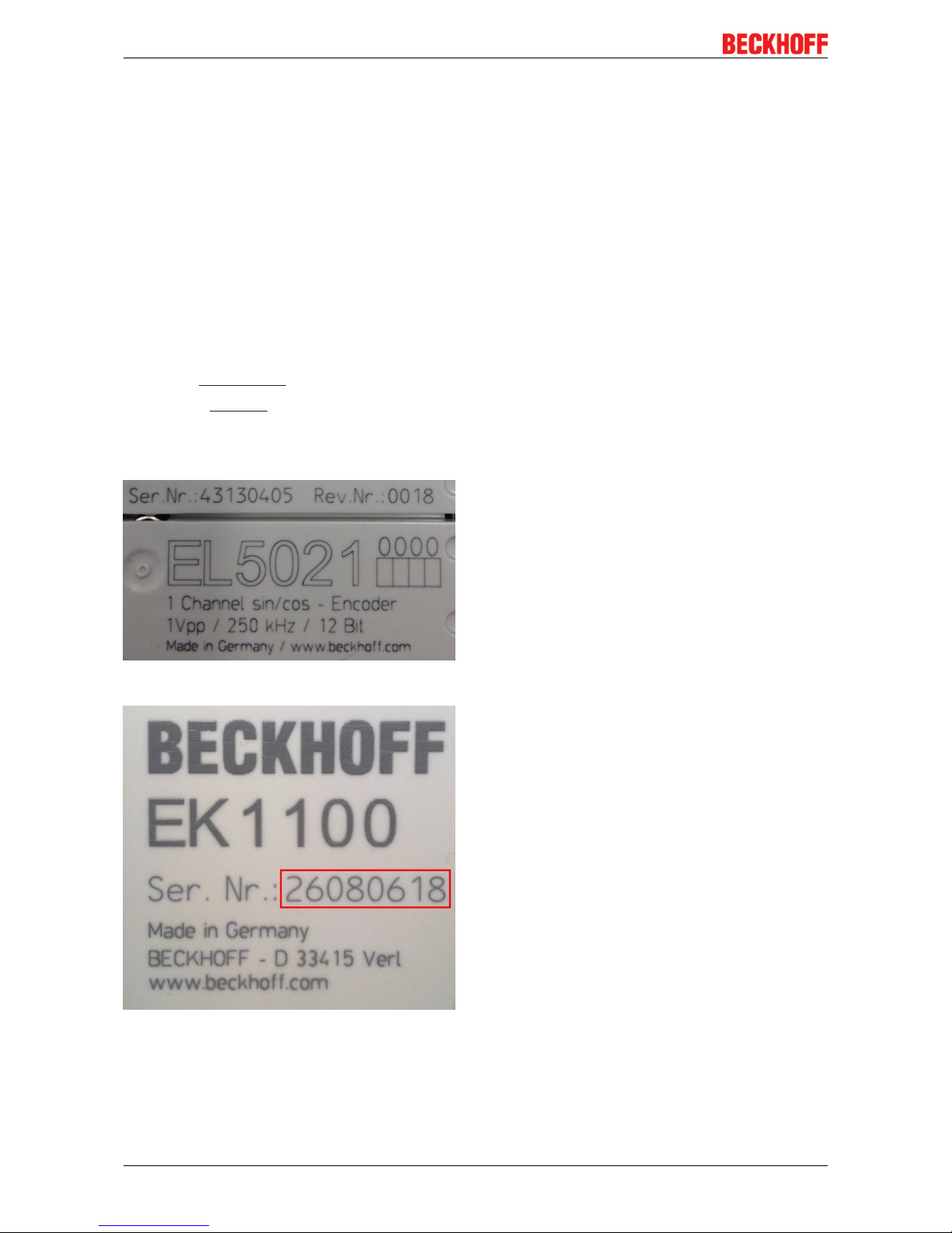
Examples of markings
Fig.1: EL5021 EL terminal, standard IP20 IO device with batch number and revision ID (since 2014/01)
Fig.2: EK1100 EtherCAT coupler, standard IP20 IO device with batch number
Foreword
EK110x, EK15xx 11Version: 3.6
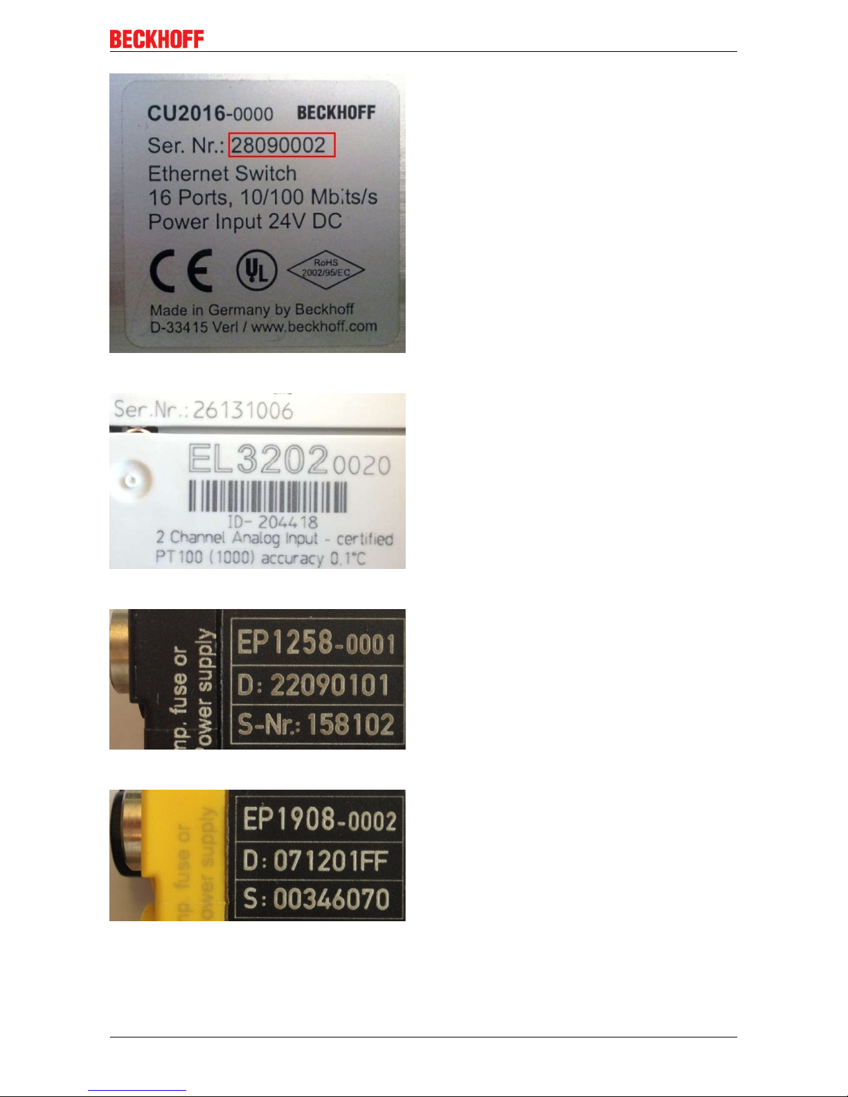
Fig.3: CU2016 switch with batch number
Fig.4: EL3202-0020 with batch numbers 26131006 and unique ID-number 204418
Fig.5: EP1258-00001 IP67 EtherCAT Box with batch number 22090101 and unique serial number 158102
Fig.6: EP1908-0002 IP67 EtherCAT Safety Box with batch number 071201FF and unique serial number
00346070
Foreword
EK110x, EK15xx12 Version: 3.6
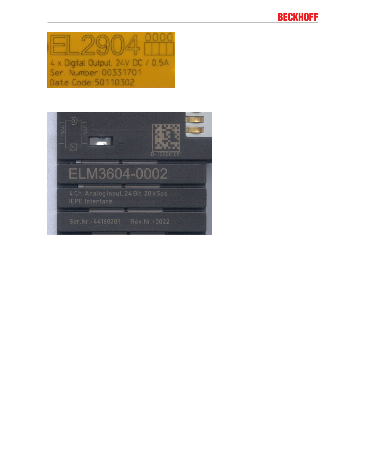
Fig.7: EL2904 IP20 safety terminal with batch number/date code 50110302 and unique serial number
00331701
Fig.8: ELM3604-0002 terminal with ID number (QR code) 100001051 and unique serial number 44160201
Product overview
EK110x, EK15xx 13Version: 3.6
2 Product overview
2.1 Overview of EtherCAT couplers
An EtherCAT coupler is required in order to connect EtherCAT Terminals with E-bus-communication (series
ELxxxx, ESxxxx, EMxxxx) to an EtherCAT network. This coupler relays the communication from the higherlevel EtherCAT network to the terminals, or functions as a master itself and generates telegrams. Beckhoff
offers different components for different application scenarios.
The selection of the correct coupler depends on the following criteria:
• is a local small controller needed?
• is the coupler to be connected via copper cable or optical fiber cable?
• is the coupler to be addressed via IP or is it located in the unswitched network?
• is the coupler to be controlled via EAP (EtherCAT Automation Protocol) or EtherCAT Device Protocol?
• required protection class: IP20 or higher?
• is the coupler to be plugged in at different places at the network using the HotConnect technique?
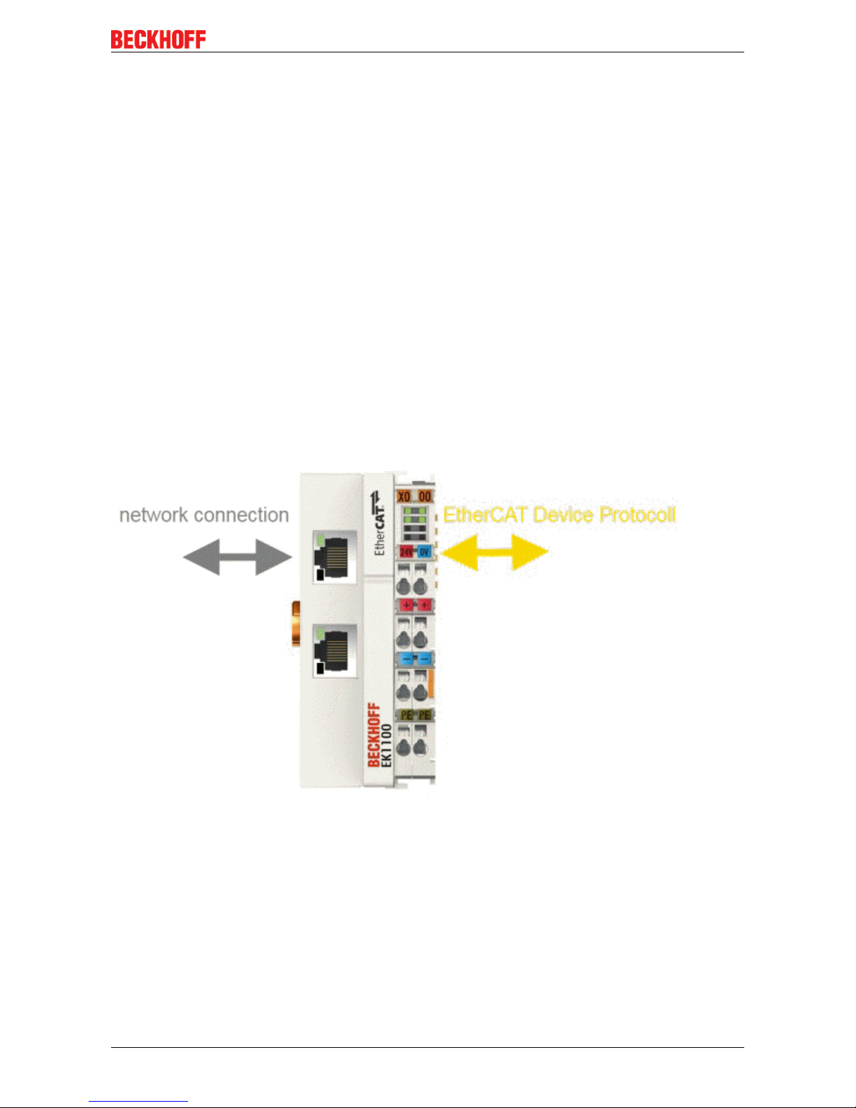
A coupler connects the added terminals to the right; it can be connected to the higher level network to the
left. Couplers that support the EtherCAT Device Protocol ‘to the left’ must be connected there to an
EtherCAT master.
Fig.9: EtherCAT coupler communication diagram
The following features overview can be used for selection (Beckhoff EtherCAT couplers):

Product overview
EK110x, EK15xx14 Version: 3.6
Characteristic EK1100 EK1101
EK1101-0080
EK1501 EK1501-0010 EK1541
Protection class IP20 IP20 IP20 IP20 IP20
Higher level
network technology
100 MBit FastEthernet
(100BASE-TX)
100 MBit FastEthernet
(100BASE-TX)
100 MBit FastEthernet
(100BASE-FX)
100 MBit FastEthernet
(100BASE-FX)
100 MBit FastEthernet
(100BASE-FX)
POF
Higher level
network - max. connection
length
100 m 100 m 2 km 20 km 50m
Higher level
network connection technology
RJ45 RJ45 SC duplex
Multi-mode optical
fiber cable
SC duplex
Single-mode optical fiber cable
Versatile Link
POF duplex connector
Polymeric Optical
Fiber
higher-level
network protocol
EtherCAT Device
Protocol
(formerly Direct
Mode)
EtherCAT Device
Protocol
(formerly Direct
Mode)
EtherCAT Device
Protocol
(formerly Direct
Mode)
EtherCAT Device
Protocol
(formerly Direct
Mode)
EtherCAT Device
Protocol
(formerly Direct
Mode)
integrated PLC - - - - -
supports HotConnect with address setting on the device
- yes
EK1101-0080:
Fast-Hot-Connect
yes yes yes
Note The EK1100 is the
"standard" coupler
for use directly on
the EtherCAT master.
Characteristic EK18xx EK9000 EKx000 EPxxxx CX8000
Protection class IP20 IP20 IP20 IP67 IP20
Higher level
network technology
100 MBit FastEthernet
(100BASE-TX)
100 MBit FastEthernet
(100BASE-TX)
diverse
see doc.
100 MBit FastEthernet
(100BASE-TX)
100 MBit FastEthernet
(100BASE-TX)
Higher level
network - max. connection
length
100 m 100 m see doc. 100 m 100 m
Higher level
network connection technology
RJ45 RJ45 see doc. M8 RJ45
higher-level
network protocol
EtherCAT Device
Protocol
(formerly Direct
Mode)
EAP see doc. EtherCAT Device
Protocol
(formerly Direct
Mode)
EtherCAT Device
Protocol
(formerly Direct
Mode)
integrated PLC - - - - yes
supports HotConnect with address setting on the device
- - - - -
Note The EK18xx de-
vices integrate a
coupler for application directly at the
EtherCAT master
and digital inputs
and outputs without
additional wiring.
The EK9000 can
be controlled in a
switched EtherCAT
network with directed IP addressing.
If the EK9000 is
provided with another fieldbus connection, this gives
rise to the appropriate EKx000 coupler.
Technologically,
each EP Box represents a self-contained EtherCAT
coupler with internally added I/O
functions.
The CX8000 appears to the higher
level EtherCAT
network as an
EtherCAT slave
while at the same
time managing its
attached I/Os as a
master.
Product overview
EK110x, EK15xx 15Version: 3.6
2.2 Coupler with RJ45 connection
2.2.1 EK1100
2.2.1.1 EK1100 - Introduction
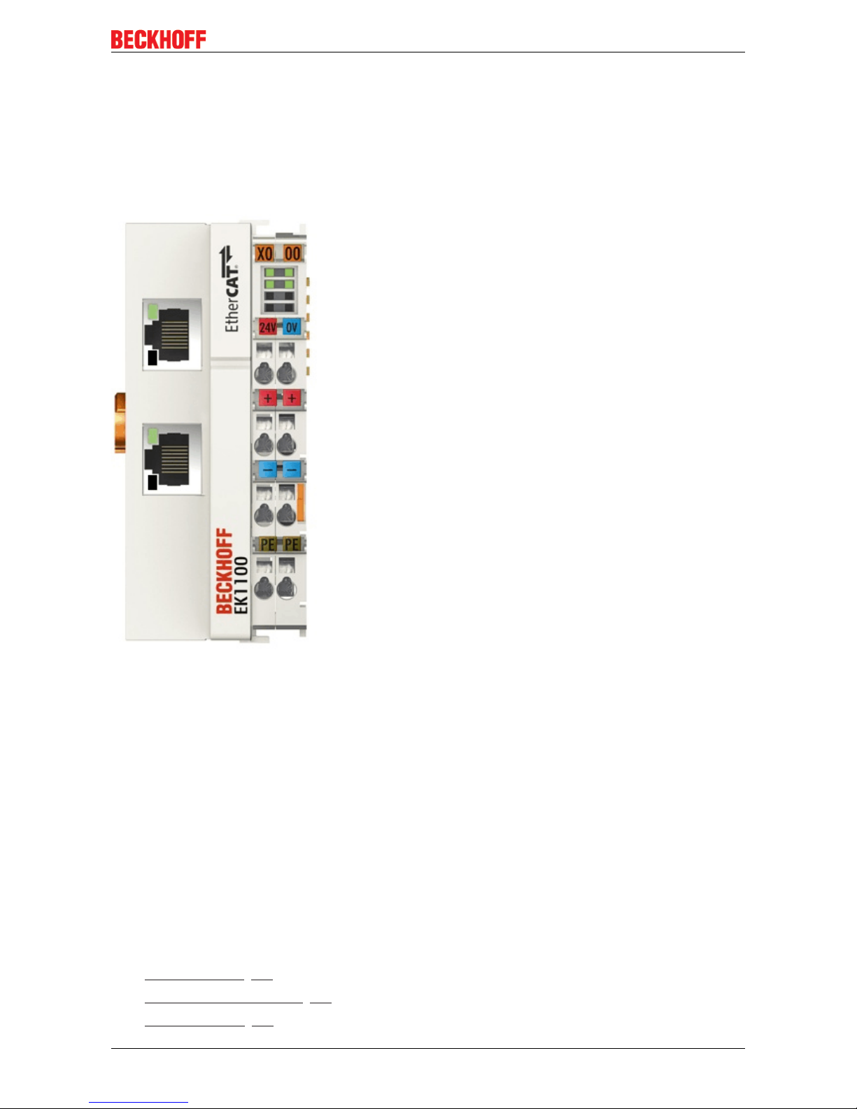
EK1100 EtherCAT Coupler
The EK1100 coupler connects the EtherCAT Device Protocol with the EtherCAT Terminals (ELxxxx/ESxxxx/
EMxxxx). One station consists of a coupler, any number of EtherCAT Terminals and a bus end terminal, e.g.
EL9011.
The coupler converts the telegrams from Ethernet 100BASE-TX to E-bus signal representation in passing
with minimum latency The coupler is connected to the network via the upper Ethernet interface. The lower
RJ-45 socket may be used to connect further EtherCAT devices in the same strand.
The coupler supplies the connected terminals with the necessary E-bus current for communication. The
coupler can supply a maximum of 5V/2A. Power feed terminals (e.g. EL9410) must be integrated if more
current is required.
In the EtherCAT network, the EK1100 coupler can be installed anywhere in the Ethernet signal transfer
section (100BASE-TX). The coupler thereby processes exclusively unaddressed MAC Broadcast telegrams
of the type EtherCAT Device Protocol from the EtherCAT master. Since directed addressing via MAC
Unicast or IP addressing is not used, neither a switch nor a router can be used.
Quick links
• EtherCAT basics [}31]
• Configuration instructions [}56]
• Diagnostic LEDs [}66]

Product overview
EK110x, EK15xx16 Version: 3.6
2.2.1.2 EK1100 - Technical data
Technical data EK1100
Task within the EtherCAT system Coupling of EtherCAT Terminals (ELxxxx) to
100BASE-TX EtherCAT networks
Number of EtherCAT Terminals Up to 65535 in the overall system
Number of peripheral signals max. 4.2GB addressable IO points
Transmission medium at least Ethernet CAT-5 cable
Cable length between two Bus Couplers max. 100m (100BASE-TX)
Protocol / Baud rate EtherCAT Device Protocol / 100MBaud
HotConnect no
Delay typical 1µs
Bus connection 2 x RJ45
Power supply 24VDC (-15%/+20%)
Current consumption 70mA + (E-bus current)/4
E-bus power supply (5 V)
(at higher current consumption the EL9410 power
feed terminal can be used in addition)
max. 2000mA (-25°C ... +55°C)
max. 1000mA (> +55°C)
Power contacts max. 24VDC, max. 10A
Electrical isolation 500V (power contact/supply voltage/EtherCAT)
Dimensions (W x H x D) approx. 44mm x 100mm x 68mm
Weight approx. 105g
Permissible ambient temperature range during
operation
-25°C ... +60°C
Permissible ambient temperature range during
storage
-40°C ... + 85°C
Permissible relative humidity 95%, no condensation
Mounting [}37]
on 35mm mounting rail conforms to EN 60715
Vibration/shock resistance conforms to EN 60068-2-6/EN 60068-2-27,
see also Installation instructions [}40] for terminals
with increased mechanical load capacity
EMC immunity/emission conforms to EN 61000-6-2 / EN 61000-6-4
Protection class IP20
Installation position variable
Approval CE
ATEX [}54]
cULus [}52]
Product overview
EK110x, EK15xx 17Version: 3.6
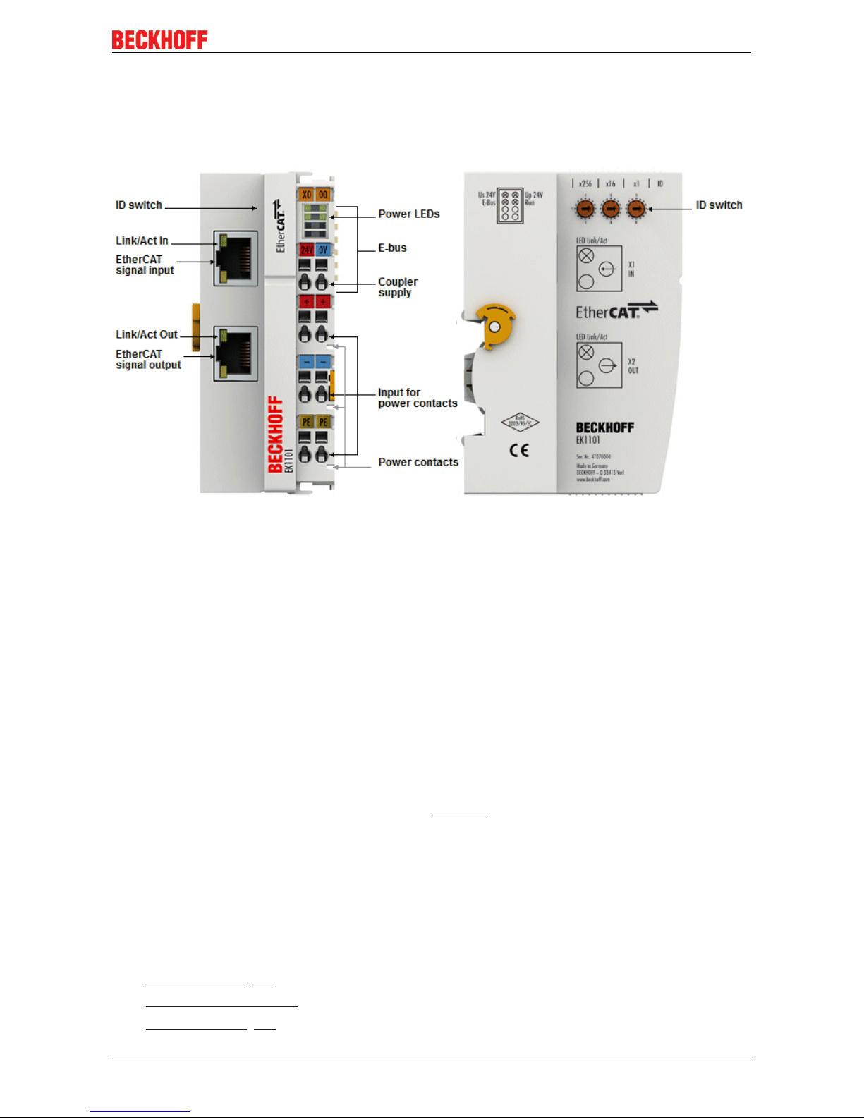
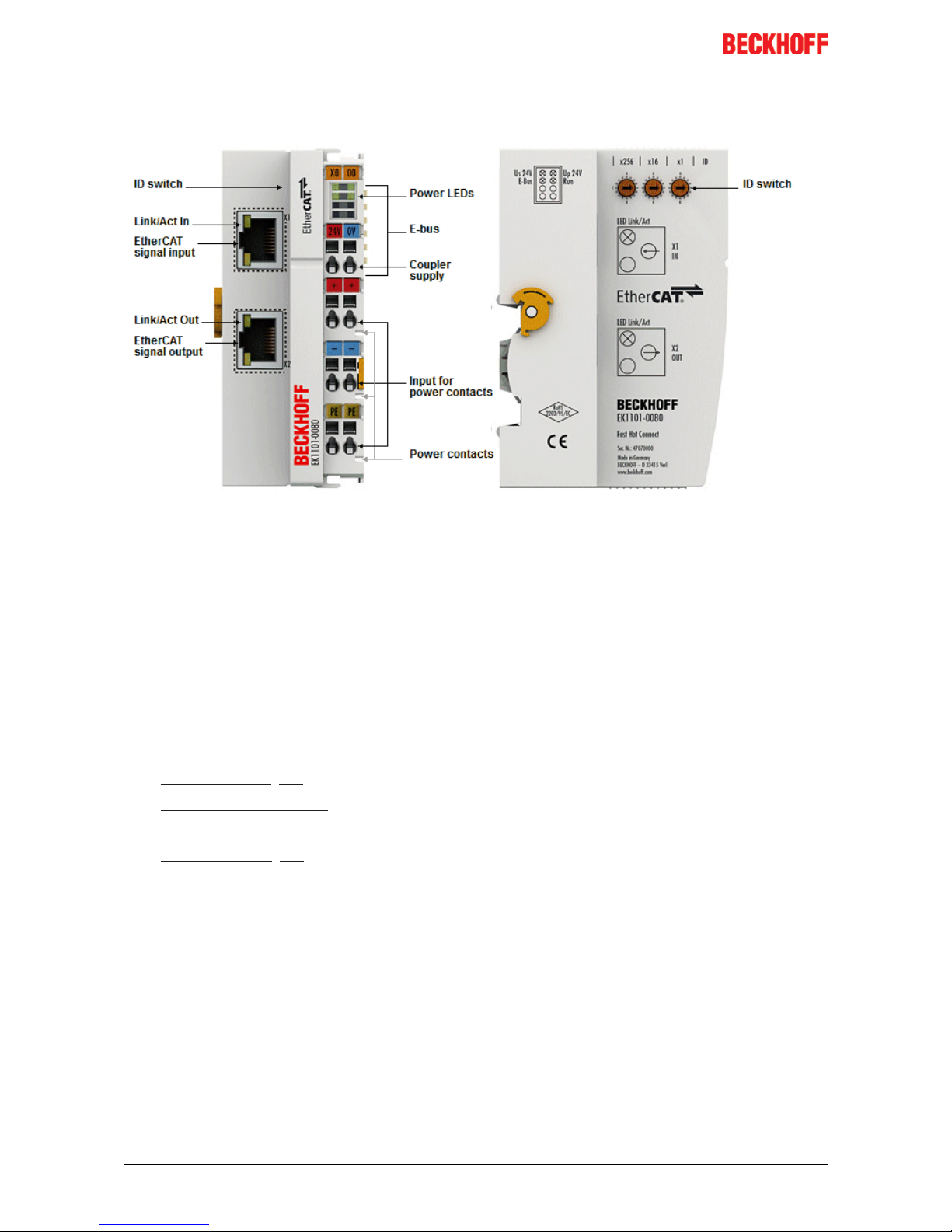
2.2.2 EK1101, EK1101-xxxx
2.2.2.1 EK1101 - Introduction
EK1101 EtherCAT coupler with ID switch
The EK1101 coupler connects the EtherCAT Device Protocol with the EtherCAT Terminals (ELxxxx/ESxxxx/
EMxxxx). One station consists of a coupler, any number of EtherCAT Terminals and a bus end terminal, e.g.
EL9011.
The coupler converts the telegrams from Ethernet 100BASE-TX to E-bus signal representation in passing
with minimum latency The coupler is connected to the network via the upper Ethernet interface. The lower
RJ-45 socket may be used to connect further EtherCAT devices in the same strand.
The coupler supplies the connected terminals with the necessary E-bus current for communication. The
coupler can supply a maximum of 5 V/2 A. Power feed terminals (e.g. EL9410) must be integrated if more
current is required.
In the EtherCAT network, the coupler can be installed anywhere in the Ethernet signal transfer section
(100BASE-TX). The coupler thereby processes exclusively unaddressed MAC Broadcast telegrams of the
type EtherCAT Device Protocol from the EtherCAT master. Since directed addressing via MAC Unicast or IP
addressing is not used, neither a switch nor a router can be used.
The EK1101 supports the HotConnect procedure, see EtherCAT documentation. The characteristics of the
EK1101 in relation to this are:
• ID can be set on the device via 3 rotary selector switches within the range 0 to 4095 (hexadecimal)
• the ID is readable online by the EtherCAT master via the process data
• if the EtherCAT master supports HotConnect, then an I/O group can be adopted dynamically into the
EtherCAT communication. This group can then be located at any position within the EtherCAT network.
Variable topologies are therefore easily implementable.
Quick links
• EtherCAT basics [}31]
• Configuration instructions
• Diagnostic LEDs [}66]
Product overview
EK110x, EK15xx18 Version: 3.6
2.2.2.2 EK1101-0080 - Introduction
EK1101-0080 EtherCAT coupler with ID switch
The EK1101-0080 EtherCAT coupler with Fast Hot Connect technology is an extension of the EK1101
coupler.
Hot Connect is an EtherCAT feature for changing topologies through direct coupling or uncoupling during
operation. Coupled EtherCAT components are already quickly linked to the data communication after
connection as standard. Fast hot-connect technology further reduces the connection time significantly,
enabling even faster tool changes. Fast hot-connect ports may only be connected to each other, which is
why they are specially identified.
The EK1101-0080 EtherCAT coupler with Fast Hot Connect is complemented by the EK1122-0080
EtherCAT junction with Fast Hot Connect.
Quick links
• EtherCAT basics [}31]
• Configuration instructions
• Notes on Fast Hot Connect [}19]
• Diagnostic LEDs [}66]

Product overview
EK110x, EK15xx 19Version: 3.6
2.2.2.3 EK1101, EK1101-0080 - Technical data
Technical data EK1101 EK1101-0080
Task within the EtherCAT system Coupling of EtherCAT Terminals
(ELxxxx) to 100BASE-TX
EtherCAT networks
Coupling of EtherCAT Terminals
(ELxxxx) to 100BASE-TX
EtherCAT networks,
Fast Hot Connect technology
Number of EtherCAT Terminals up to 65535 in the overall system
Number of peripheral signals max. 4.2GB addressable IO points
Transmission medium at least Ethernet CAT-5 cable
Cable length between two Bus
Couplers
max. 100m (100BASE-TX)
Protocol / Baud rate EtherCAT Device Protocol / 100MBaud
HotConnect max. number of configurable IDs: 4096
Delay typical 1µs
Bus connection 2 x RJ45
Power supply 24VDC (-15%/+20%)
Current consumption 70mA + (E-bus current)/4
E-bus power supply (5 V)
depending on ambient temperature
(at higher current consumption the
EL9410 power feed terminal can be
used in addition)
max. 2000mA (-25°C ... +55°C)
max. 1000mA (> +55°C)
Power contacts max. 24VDC, max. 10A
Electrical isolation 500V (power contact/supply voltage/EtherCAT)
Dimensions (W x H x D) approx. 44mm x 100mm x 68mm
Weight approx. 105g
Permissible ambient temperature
range during operation
-25°C ... +60°C
Permissible ambient temperature
range during storage
-40°C ... + 85°C
Permissible relative humidity 95%, no condensation
Mounting [}37]
on 35mm mounting rail conforms to EN 60715
Vibration/shock resistance conforms to EN 60068-2-6 / EN 60068-2-27
EMC immunity/emission conforms to EN 61000-6-2 / EN 61000-6-4
Protection class IP20
Installation position variable
Approval CE
ATEX [}54]
cULus [}52]
2.2.2.4 Notes re. EtherCAT Fast Hot Connect technology
EtherCAT components that support Fast Hot Connect enable a faster fieldbus boot up following the
establishment of a connection. The boot up depends in detail on the number of devices, the topology and
activated Distributed Clocks. Whereas the normal establishment of a connection and communication takes
several seconds, less than 1 second is possible with FHC components.
Properties and system behavior
• Fast Hot Connect is supported from TwinCAT 2.11R3 Build 2221.
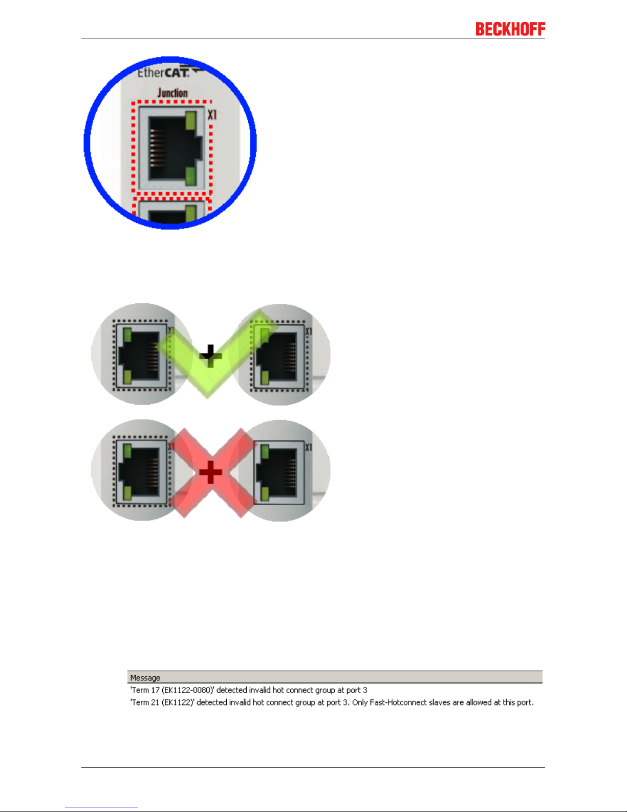
• Fast Hot Connect ports are specially marked.
Product overview
EK110x, EK15xx20 Version: 3.6
Fig.10: Identification of FHC port at EK1122-0080 and EK1101-0080
• Standard EtherCAT devices may not be connected to Fast Hot Connect ports. This is to be ensured by
measures on the application side, which is easy to implement by means of the topology change that is
usually carried out mechanically in such applications.
Fig.11: Recommended combination of Ethernet ports
• If corresponding ports are nevertheless connected, a power reset of the devices involved (branch
terminal and coupler/box) is required.
• With Fast Hot Connect devices the establishment of an Ethernet connection is accelerated compared
to the normal Fast Ethernet connection.
If in addition the use of Distributed Clocks functions is omitted in the entire topology, then the
resynchronization time of the components is also dispensed with. Group boot up of < 1 second is then
possible, from plugging in the Ethernet connection to the OP state.
• An incorrect port allocation is detected in the TwinCAT ADS Logger
Product overview
EK110x, EK15xx 21Version: 3.6
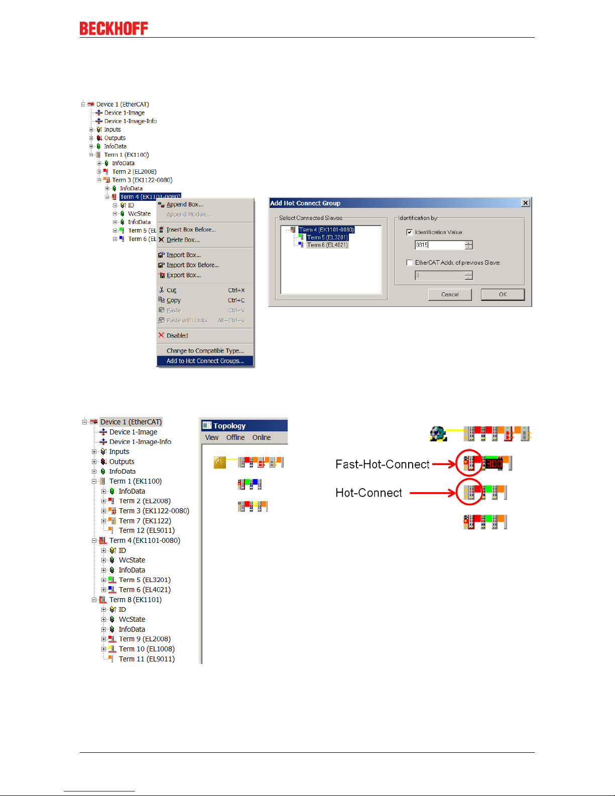
Configuration
The configuration of Fast Hot Connect groups in the TwinCAT System Manager takes place in exactly the
same way as Hot Connect groups, specifying the associated group ID.
Fig.12: Configuration of a Fast Hot Connect group
Corresponding Fast Hot Connect ports are marked red in the TwinCAT System Manager.
Fig.13: Marking in the TwinCAT System Manager
A configuration of FHC groups is possible only if at least 1 corresponding junction is present e.g.
EK1122-0080.
Product overview
EK110x, EK15xx22 Version: 3.6
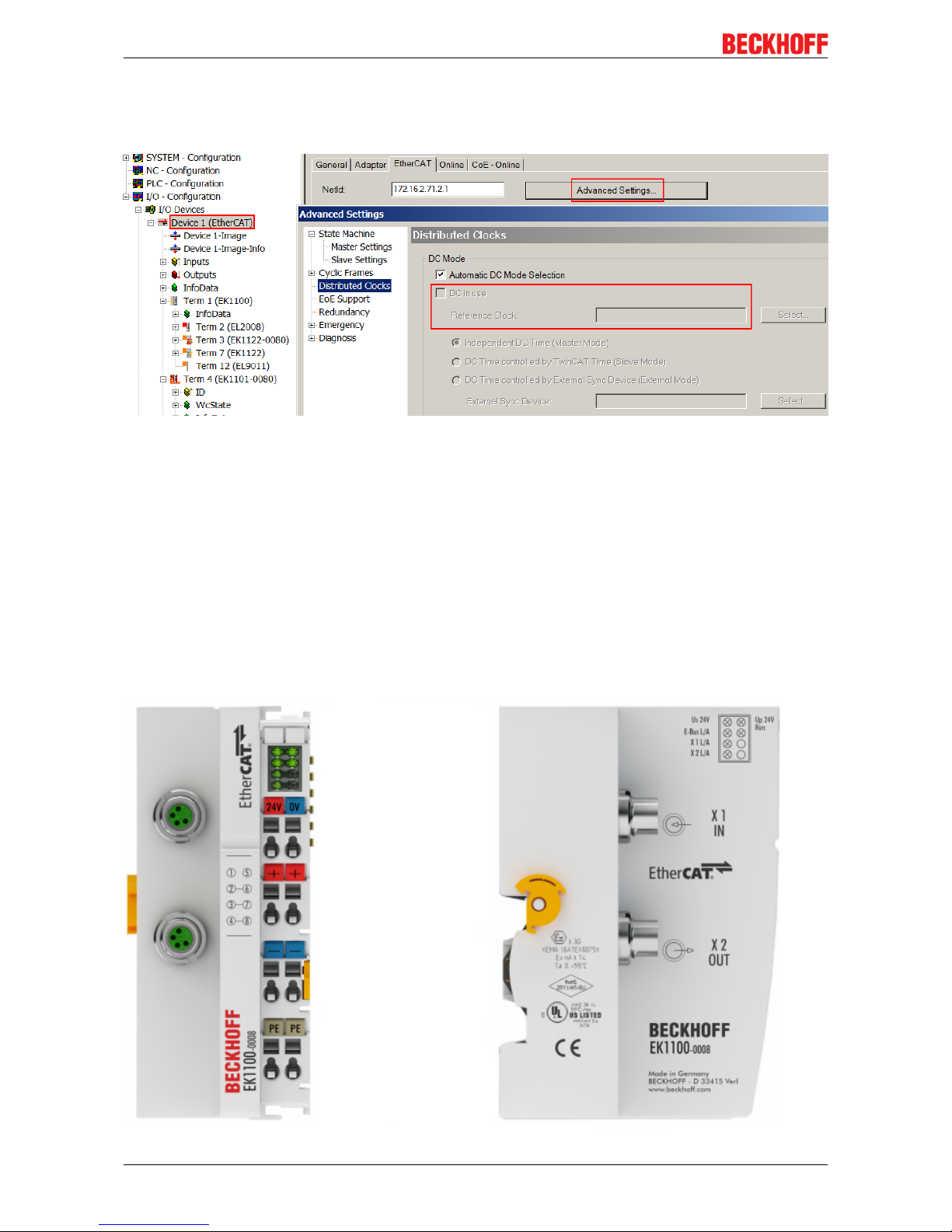
Distributed Clocks
If no Distributed Clocks functions are used, this is visible in the master settings by the absence of "DC in
use":
Fig.14: DC master setting
This setting is automatically selected by the System Manager if there are no EtherCAT slaves in the
configuration in which Distributed Clocks is activated. "DC in use" should not be randomly deactivated by the
user, because otherwise these devices will no longer function.
2.3 Coupler with M8 connection
2.3.1 EK1100-0008
2.3.1.1 EK1100-0008 - Introduction

Product overview
EK110x, EK15xx 23Version: 3.6
EtherCAT coupler EK1100-0008 (M8 connection)
The EK1100-0008 coupler connects EtherCAT with the EtherCAT Terminals (ELxxxx/ESxxxx). One station
consists of a coupler EK1100-0008, any number of EtherCAT Terminals and a bus end terminal.
The coupler converts the telegrams from Ethernet 100BASE-TX to E-bus signal representation. Compared to
EK1100 the EK1100-0008 has two M8 sockets instead of two RJ45 sockets, compatible to the ones of the
EtherCAT-Boxes.
The upper Ethernet interface is used to connect the coupler to the network; the lower M8 socket serves for
the optional connection of further EtherCAT devices in the same strand.
The coupler supplies the connected terminals with the necessary E-bus current for communication. The
coupler can supply a maximum of 5V/2A. Power feed terminals (e.g. EL9410) must be integrated if more
current is required.
In the EtherCAT network, the EK1100-0008 coupler can be installed anywhere in the Ethernet signal transfer
section (100BASE-TX) except onto the switch directly. By using respective powerful Ethernet cables e.g.
ZK1090-3131-1xxx distances of 100m are also possible via M8.
Quick links
• EtherCAT basics [}31]
• Configuration instructions [}56]
• Diagnostic LEDs [}66]

Product overview
EK110x, EK15xx24 Version: 3.6
2.3.1.2 EK1100-0008 - Technical data
Technical data EK1100-0008
Task within the EtherCAT system Coupling of EtherCAT Terminals (ELxxxx) to
100BASE-TX EtherCAT networks
Number of EtherCAT Terminals up to 65535 in the overall system
Transmission medium at least EtherCAT CAT-5 cable
Cable length between two Bus Couplers max. 100m (100BASE-TX)
Transfer rate 100MBaud
Configuration Not required
Delay typical 1µs
Bus interface 2 x M8
Power supply 24VDC (-15%/+20%)
Current consumption from US 70mA + (∑ E-Bus-Strom/4)
Current consumption from UP Load
Power supply E-bus max. 2000mA (-25°C ... +55°C)
Power contacts max. 24VDC, max. 10A
Electrical isolation 500V (power contact/supply voltage/EtherCAT)
Dimensions (W x H x D) approx. 44mm x 100mm x 68mm
Weight approx. 105g
Permissible ambient temperature range during
operation
-25°C ... +60°C
Permissible ambient temperature range during
storage
-40°C ... + 85°C
Permissible relative humidity 95%, no condensation
Mounting [}37]
on 35 mm mounting rail conforms to EN 60715
Vibration/shock resistance conforms to EN 60068-2-6/EN 60068-2-27,
see also Installation instructions [}40] for terminals
with increased mechanical load capacity
EMC immunity/emission conforms to EN 61000-6-2 / EN 61000-6-4
Protection class IP20
Installation position variable
Approval CE
ATEX [}54]
cULus [}52]
Product overview
EK110x, EK15xx 25Version: 3.6
2.4 Coupler with optical fiber connection
2.4.1 EK1501
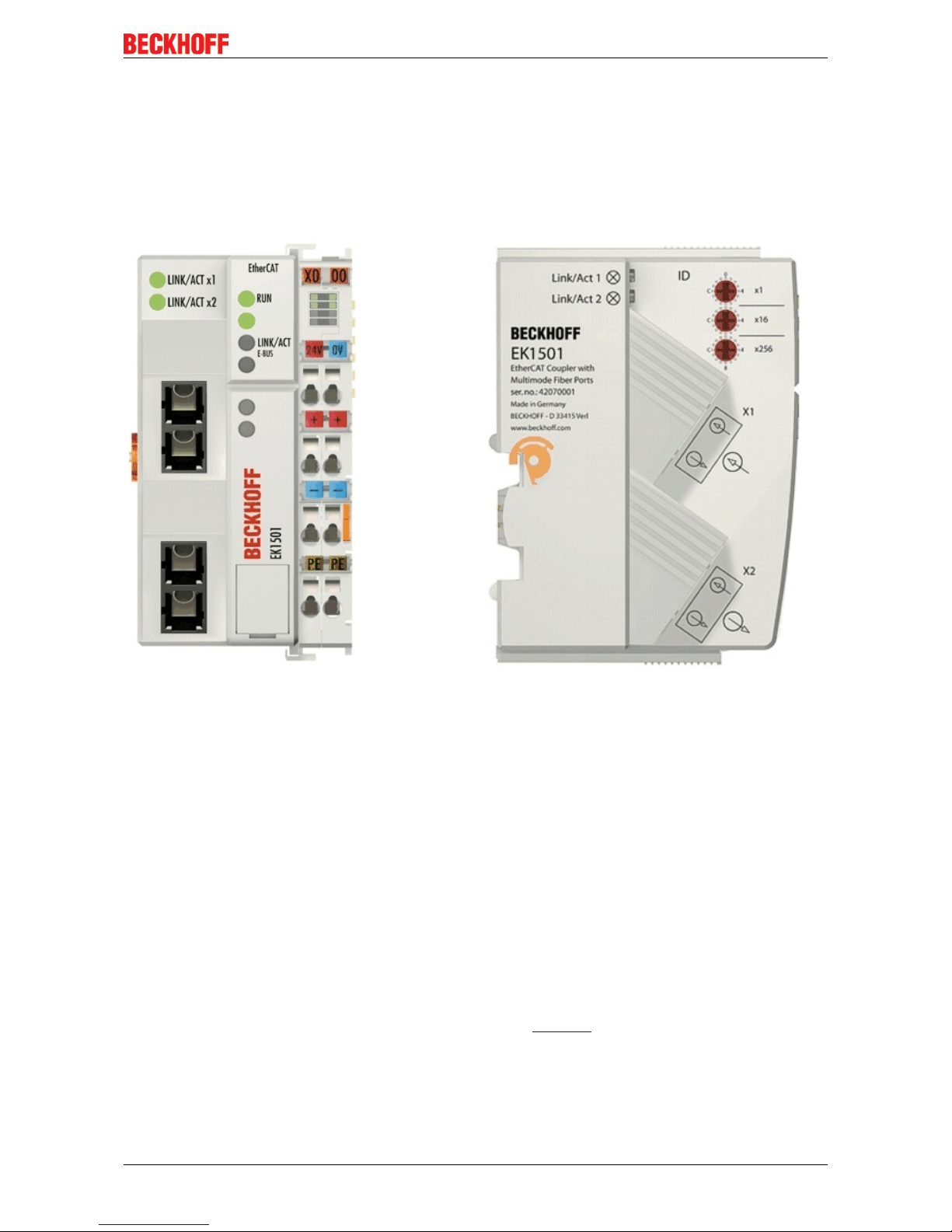
2.4.1.1 EK1501 - Introduction
EK1501 EtherCAT coupler with ID switch, multimode optical fiber connection
The EK1501 coupler connects the EtherCAT Device Protocol with the EtherCAT Terminals (ELxxxx/ESxxxx/
EMxxxx). One station consists of a coupler, any number of EtherCAT Terminals and a bus end terminal, e.g.
EL9011.
The coupler converts the telegrams from Ethernet 100BASE-FX to E-bus signal representation in passing
with minimum latency The upper Ethernet interface is used to connect the coupler to the network; the lower
SC socket serves for the optional connection of further EtherCAT devices in the same strand.
The coupler supplies the connected terminals with the necessary E-bus current for communication. The
coupler can supply a maximum of 5V/2A. Power feed terminals (e.g. EL9410) must be integrated if more
current is required.
In the EtherCAT network, the coupler is used at an arbitrary place in the Ethernet signal transmission range
(100BASE-FX). The coupler thereby processes exclusively unaddressed MAC Broadcast telegrams of the
type EtherCAT Device Protocol from the EtherCAT master. Since directed addressing via MAC Unicast or IP
addressing is not used, neither a switch nor a router can be used.
The multimode glass fiber connection enables distances of up to 2 km between two couplers.
The coupler supports the HotConnect technique; see the basic EtherCAT documentation regarding this. The
characteristics of the EK1501 in relation to this are:
• ID can be set on the device via 3 rotary selector switches within the range 0 to 4095 (hexadecimal)
• the ID is readable online by the EtherCAT master via the process data

Product overview
EK110x, EK15xx26 Version: 3.6
• if the EtherCAT master supports HotConnect, then an I/O group can be adopted dynamically into the
EtherCAT communication. This group can then be located at any position within the EtherCAT network.
Variable topologies are therefore easily implementable.
Quick links
• EtherCAT basics [}31]
• Application notes [}56]
• Diagnostic LEDs [}66]
2.4.1.2 EK1501 - Technical data
Technical data EK1501
Task within the EtherCAT system Coupling of EtherCAT Terminals (ELxxxx) to
100BASE-FX EtherCAT networks
Number of EtherCAT Terminals up to 65535 in the overall system
Number of peripheral signals max. 4.2GB addressable IO points
Transmission medium Multimode glass fiber (MM)
Cable length between two Bus Couplers max. 2km (100BASE-FX)
Transceiver wavelength typically 1300nm
Protocol / Baud rate EtherCAT Device Protocol / 100MBaud
HotConnect max. number of configurable IDs: 4096
Delay typical 1µs
Bus connection 2 x SC Duplex
Power supply 24VDC (-15%/+20%)
Current consumption 130mA + (E-bus current)/4
E-bus power supply (5 V)
depending on ambient temperature
(at higher current consumption the EL9410 power
feed terminal can be used in addition)
max. 2000mA (-25°C ... +55°C)
max. 1000mA (> +55°C)
Power contacts max. 24VDC, max. 10A
Electrical isolation 500 V (power contact/supply voltage/EtherCAT)
Dimensions (W x H x D) approx. 49mm x 100mm x 70mm
Weight approx. 190g
Permissible ambient temperature range during
operation
-25°C ... +60°C (extended temperature range)
Permissible ambient temperature range during
storage
-40°C ... + 85°C
Permissible relative humidity 95%, no condensation
Mounting [}37]
on 35 mm mounting rail conforms to EN 60715
Vibration/shock resistance conforms to EN 60068-2-6 / EN 60068-2-27
EMC immunity/emission conforms to EN 61000-6-2 / EN 61000-6-4
Protection class IP20
Installation position variable
Approval CE
ATEX [}54]
cULus [}52]
 Loading...