


AL2009
Beckhoff AL2009, AL2003, AL2006, AL2012, AL2018 Operation Manual
...
Operation Manual
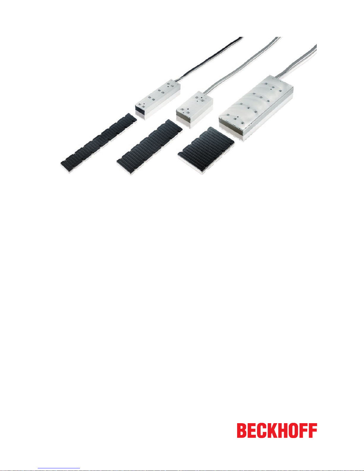
Linear servomotor AL2xxx
Air and water-cooled options
6.2
2018-09-21
Version:
Date:


Table of contents
Linear servomotor AL2xxx 3
Version: 6.2
Table of contents
1 Foreword ....................................................................................................................................................5
1.1 Notes on the documentation..............................................................................................................5
1.2 Documentation issue status ..............................................................................................................6
1.3 Intended use......................................................................................................................................7
2 Guidelines and Standards ........................................................................................................................8
2.1 EC declaration of conformity .............................................................................................................8
3 For your safety...........................................................................................................................................9
3.1 Staff qualification ...............................................................................................................................9
3.2 Description of symbols ....................................................................................................................10
3.3 Notes on the AL2xxx linear motors..................................................................................................11
4 Handling ...................................................................................................................................................14
4.1 Transport .........................................................................................................................................14
4.2 Storage ............................................................................................................................................14
4.3 Maintenance / Cleaning...................................................................................................................15
4.4 Disposal...........................................................................................................................................15
5 Product identification..............................................................................................................................16
5.1 AL2xxx scope of delivery.................................................................................................................16
5.2 AL2xxx name plate ..........................................................................................................................16
5.3 AL2xxx type key ..............................................................................................................................16
6 Technical description..............................................................................................................................17
6.1 Design of the motors .......................................................................................................................17
6.2 General technical data.....................................................................................................................17
6.2.1 Power derating................................................................................................................. 17
6.3 Standard features ............................................................................................................................18
6.3.1 Coil unit, primary part (N/S) ............................................................................................. 18
6.3.2 Magnetic plate, secondary part........................................................................................ 18
6.3.3 Magnetic Encoder System (MES) (optional).................................................................... 19
6.4 Additional equipment .......................................................................................................................19
6.4.1 Servo drive and feedback system.................................................................................... 20
7 Mechanical installation ...........................................................................................................................21
7.1 Important notes................................................................................................................................21
7.2 Order of assembly of the work unit..................................................................................................22
7.3 Assembling the magnetic plates......................................................................................................23
7.3.1 Inserting the locating pins ................................................................................................ 23
7.3.2 Attachment of the magnetic plates .................................................................................. 24
7.3.3 Coil unit and magnetic plate ............................................................................................ 24
7.4 Coupling of linear servomotors........................................................................................................25
7.4.1 Temperature sensor ........................................................................................................ 25
7.4.2 Layout of the motors ........................................................................................................ 25
7.4.3 Calculation of the offset ................................................................................................... 26
7.4.4 Layout of the wiring.......................................................................................................... 26
7.4.5 Positions of the phase lines ............................................................................................. 27
7.4.6 Minimum distance between the motors ........................................................................... 29

Table of contents
Linear servomotor AL2xxx4
Version: 6.2
7.5 Dismantling sequence .....................................................................................................................30
8 Electrical installation...............................................................................................................................31
8.1 Important notes................................................................................................................................31
8.2 Connection of motors ......................................................................................................................32
8.2.1 Single conductors ............................................................................................................ 32
8.2.2 M23 connector for power supply and D-Sub connector for temperatur contact .............. 33
8.3 Connection with pre-assembled cables and connector box AL225x ...............................................34
8.3.1 AX5000 connection diagram with MES and Sin/Cos encoder without zero pulse........... 35
8.3.2 AX5000 connection diagram for AL2xxx and absolute value encoder ............................ 36
8.3.3 AX5000 connection diagram for AL2xxx and Sin/Cos encoder with zero pulse ............. 37
8.3.4 AX5000 connection diagram for AL2xxx and TTL encoder with zero pulse ................... 38
8.4 Temperature sensor ........................................................................................................................39
8.4.1 PTC specification............................................................................................................. 39
8.4.2 KTY Specification ............................................................................................................ 39
8.5 Polarity test......................................................................................................................................40
9 Installation of the water cooling.............................................................................................................41
9.1 General............................................................................................................................................41
9.2 Requirements ..................................................................................................................................41
9.3 Installation of the water cooling connections ...................................................................................42
9.3.1 AL2xxx ............................................................................................................................. 42
9.3.2 AL28xx-1 water-cooled .................................................................................................... 42
9.4 Connecting the hoses......................................................................................................................43
10 Commissioning........................................................................................................................................44
10.1 Important notes................................................................................................................................44
10.2 General commissioning ...................................................................................................................44
10.2.1 Parameterisation.............................................................................................................. 44
10.2.2 Commissioning ................................................................................................................ 45
10.2.3 Optimising the control settings......................................................................................... 45
10.3 Troubleshooting...............................................................................................................................46
11 Technical data..........................................................................................................................................47
11.1 Term definitions ...............................................................................................................................47
11.2 AL20xx.............................................................................................................................................48
11.2.1 Dimensional drawing, AL20xx and AL21xx ..................................................................... 50
11.3 AL24xx.............................................................................................................................................51
11.3.1 Dimensional drawing, AL24xx and AL25xx ..................................................................... 52
11.4 AL28xx-0 air-cooled.........................................................................................................................53
11.4.1 Dimensional drawing, AL28xx-0 air-cooled and AL29xx ................................................. 54
11.5 AL28xx-1 water-cooled....................................................................................................................55
11.5.1 Dimensional drawing, AL28xx-1 water-cooled and AL29xx............................................. 56
11.6 Calculation of the brake resistor ......................................................................................................57
12 Support and Service................................................................................................................................58
Foreword
Linear servomotor AL2xxx 5
Version: 6.2
1 Foreword
1.1 Notes on the documentation
This description is only intended for the use of trained specialists in control and automation engineering who
are familiar with the applicable national standards.
It is essential that the documentation and the following notes and explanations are followed when installing
and commissioning the components.
It is the duty of the technical personnel to use the documentation published at the respective time of each
installation and commissioning.
The responsible staff must ensure that the application or use of the products described satisfy all the
requirements for safety, including all the relevant laws, regulations, guidelines and standards.
Disclaimer
The documentation has been prepared with care. The products described are, however, constantly under
development.
We reserve the right to revise and change the documentation at any time and without prior announcement.
No claims for the modification of products that have already been supplied may be made on the basis of the
data, diagrams and descriptions in this documentation.
Trademarks
Beckhoff®, TwinCAT®, EtherCAT®, Safety over EtherCAT®, TwinSAFE®, XFC® and XTS® are registered
trademarks of and licensed by Beckhoff Automation GmbH.
Other designations used in this publication may be trademarks whose use by third parties for their own
purposes could violate the rights of the owners.
Patent Pending
The EtherCAT Technology is covered, including but not limited to the following patent applications and
patents:
EP1590927, EP1789857, DE102004044764, DE102007017835
with corresponding applications or registrations in various other countries.
The TwinCAT Technology is covered, including but not limited to the following patent applications and
patents:
EP0851348, US6167425 with corresponding applications or registrations in various other countries.
EtherCAT® is registered trademark and patented technology, licensed by Beckhoff Automation GmbH,
Germany
Copyright
© Beckhoff Automation GmbH & Co. KG, Germany.
The reproduction, distribution and utilization of this document as well as the communication of its contents to
others without express authorization are prohibited.
Offenders will be held liable for the payment of damages. All rights reserved in the event of the grant of a
patent, utility model or design.

Foreword
Linear servomotor AL2xxx6
Version: 6.2
1.2 Documentation issue status
Origin of the document
This documentation was originally written in German. All other languages are derived from the German
original.
Product features
Only the product features specified in the current user documentation are valid. Further information given on
the product pages of the Beckhoff homepage, in emails or in other publications is not authoritative.
Issue Comment
6.2 Chapter revision:
Technical data AL20xx 11.2; Technical data AL24xx 11.3; Technical data AL28xx-0 aircooled 11.4; AL28xx-1 water-cooled 11.5
Removed Chapter:
M23 connector for power supply and temperature contact 8.2.3
6.1 Chapter revision:
EC declaration of conformity 2.1; AL2xxx name plate 5.2; AL2xxx type key 5.3;
Connection of motors with 8.2 Connection diagrams for AL2xxx 8.3.1 – 8.3.4; Technical
data AL2418 11.3
New chapter:
M23 connector for power supply and temperature contact 8.2.3
6.0 Complete revision
5.8 Chapter revision:
Technical data 10.2 – 10.5
5.7 Chapter revision:
Disposal 4.5
5.6 Chapter revision:
EC Declaration of Conformity 2.1; Technical data 11
5.5 Chapter revision:
1.0 Foreword; 3.0 Safety
5.4 Chapter revision:
Documented motors; 6.3.3; 7.4.2; 8.2.2; 8.4.2; 11.2; 11.3; 11.4; 11.5; 11.5.1
5.3 Chapter revision:
11.2; 11.3; 11.4; 11.5
5.2 Chapter revision
8.2 became 8.3; 3.2
New chapter
8.2; 8.2.1; 8.2.2
5.1 Chapter revision
Documented motors - chapter; 3.2; 11; 11.1: 11.2; 11.3; 11.4; 11.5
5.0 Chapter revision
Documented motors - chapter; 1.2; 2.1; 3.2; 4.2; 4.3; 4.5; 6.3.2; 6.3.3; 7; 7.3; 7.3.2; 7.4.6;
7.5; 8.2.1; 8.2.2; 8.2.3; 8.2.4; 8.3.2; 9.3.1;10; 10.2.3; 10.3; 11; 11.1; 11.2; 11.2.1; 11.4;
11.5.1; 11.6
Complete revision
Foreword
Linear servomotor AL2xxx 7
Version: 6.2
1.3 Intended use
Linear servo motors from the AL2xxx series are intended exclusively for driving handling devices, textile
machines, machine tools, packaging machines and similar machines that place high demands on the
dynamics.
The linear motors are installed exclusively as components in electrical systems or machines and may only be
put into operation as integrated components of the plant or machine.
The thermal protection contact incorporated in the motor windings must be analyzed and monitored.
WARNING
Caution - Risk of injury!
Basically, electronic devices are not fail-safe. The machine manufacturer is responsible for ensuring that
the connected motors and the machine are brought into a safe state in the event of a fault in the drive system.
The linear motors may be operated only under the environmental and operating conditions [
}17] defined
in this documentation.
Improper use
Beckhoff linear motors from the AL2xxx series are not suitable for use in the following areas:
• in ATEX zones without a suitable housing
• in areas with aggressive environments (e.g. aggressive gases or chemicals)
The relevant standards and directives for EMC interference emissions must be complied with in residential
areas.
Guidelines and Standards
Linear servomotor AL2xxx8
Version: 6.2
2 Guidelines and Standards
CAUTION
Personal injuries!
Linear servomotors from the AL2xxx series are not products within the meaning of the EU machinery directive. Operation of the linear servomotors in machines or systems is only permitted once the machine or system manufacturers has provided evidence of CE conformity of the complete machine or system.
2.1 EC declaration of conformity
Provision of EU Declaration of Conformity:
Beckhoff Automation GmbH & Co. KG will be glad to provide you with EU declarations of conformity
and manufacturer's declarations for all products upon request to info@beckhoff.com.

For your safety
Linear servomotor AL2xxx 9
Version: 6.2
3 For your safety
Read the section on safety and heed the notices to protect yourself against personal injury and material
damages.
Limitation of liability
The entire components of the Beckhoff AL2xxx linear motors are delivered in certain hardware and software
configurations according to the application requirements. Unauthorized modifications to the hardware and/or
software configurations other than those described in the documentation are not permitted, and nullify the
liability of Beckhoff Automation GmbH & Co. KG.
In addition, the following actions are excluded from the liability of Beckhoff Automation GmbH & Co.
KG:
• Failure to comply with this documentation
• Improper use [
}7]
• Untrained personnel
• Use of unauthorized spare parts
3.1 Staff qualification
All depicted work to be done on the Beckhoff software and hardware, and in particular on the AL2xxx linear
motors, may be carried out only by technical personnel with knowledge of control and automation
technology.
The technical personnel must have knowledge of drive technology and electrical systems and must also
know how to work safely on electrical equipment and machines.
This also includes:
• production planning and
• securing of the working environment (e.g. securing the control cabinet against being switched on
again).
The technical personnel must be familiar with the current and necessary standards and directives for the
automation and drive environment.
For your safety
Linear servomotor AL2xxx10
Version: 6.2
3.2 Description of symbols
In this documentation the following symbols are used with an accompanying safety instruction or note. The
safety instructions must be read carefully and followed without fail!
Symbols that warn of personal injury:
DANGER
Serious risk of injury!
This is an extremely dangerous situation. Disregarding the safety notice will lead to serious permanent injuries or even death.
WARNING
Risk of injury!
This is a dangerous situation. Disregarding the safety notice may lead to serious injuries.
CAUTION
Personal injuries!
This is a dangerous situation. Disregarding the safety notice may lead to minor injuries.
Symbols that warn of damage to property or equipment:
NOTE
Warning of damage to property or the environment!
This notice indicates disturbances in the operational procedure that could damage the product or the environment.
Symbols indicating further information or tips:
Tip or pointer!
This notice provides important information that will be of assistance in dealing with the product or
software. There is no immediate danger to product, people or environment.
UL note!
This symbol indicates important information regarding UL certification.
For your safety
Linear servomotor AL2xxx 11
Version: 6.2
3.3 Notes on the AL2xxx linear motors
The notes are intended to avert danger and to provide instructions on the handling of the AL2xxx linear
motors. They must be followed during installation, commissioning, production, troubleshooting, maintenance
and trial or test assemblies.
The linear motors from the AL2xxx series cannot run as stand-alone devices. They must always be installed
in a machine or system. After installation the additional documentation and safety instructions provided by
the machine manufacturer must be read and followed.
DANGER
Danger to life due to high voltage on the DC link capacitors of the servo drive AX8000!
The DC link capacitors RB+ and RB- and the test contacts DC+ and DC- on the
supply, axis and option modules can carry life-threatening voltages of
≥ 875 VDC.
Take the following measures to avert danger:
• After disconnecting the servo drive from the mains supply, wait until the voltage has fallen below 50
VDC. Only then is it safe to work.
• Measure the voltage on the test contacts properly.
• Secure the work area properly and wear the PPE.
DANGER
Deadly danger due to high voltage on the DC link capacitors of the AX5000 servo drive!
Due to the DC link capacitors, the DC link terminal points "ZK+ and ZK- (DC+ and DC-)" and "RB+ and
RB-" may be subject to dangerous voltages of up to 875VDC, even after the servo drive was disconnected
from the mains supply.
Take the following measures to avert danger:
• Wait:
- 5 minutes in the case of the AX5101 - AX5125 and AX520x
- 15 minutes in the case of the AX5140/AX5160/AX5172
- 30 minutes in the case of the AX5190/AX5191
- 45 minutes in the case of the AX5192/AX5193
after disconnecting the servo drive from the mains supply. It is only safe to work after the voltage has
dropped below 50 V.
• Measure the voltage on the test contacts properly.
• Secure the working area properly and wear the PPE.
CAUTION
Proper connection of the protective earth conductor!
Protective earth systems must be connected when installing electrical systems and components.
Please observe the following notes when installing the protective earth conductor:
• Make sure that the protective earth conductor has been firmly connected.
• Disconnect the servo drive and all electrical components from the mains supply. Secure the control
cabinet and the devices against being switched on again.
• Wear PPE.
For your safety
Linear servomotor AL2xxx12
Version: 6.2
WARNING
Risk of severe burns due to hot surfaces on the linear motor!
During the operation of the system the surface temperature of the linear motors can reach ≥ 50°C. There is
an acute risk of sustaining burns to parts of the body and limbs.
Take the following measures to avert danger:
• Do not touch any components (housing, etc.) shortly after or during operation.
• Wait until all components have cooled sufficiently. At least 15 minutes.
• Check the surface temperature with a thermometer.
• DO NOT wear work gloves with a rubber coating. These can fuse with the skin on account of the high
temperature and cause serious injuries.
Notes on the operation of the AL2xxx linear motors:
• Read this manual carefully and completely before using the linear motor. Notify the responsible
sales office immediately if any passages are not understandable. Do not work on the linear motor.
• Adhere without fail to the climatic conditions for the installation. Further information can be
found in the Technical data
[}47] and Mechanical installation [}21] sections.
NOTE
High temperatures can damage the magnets!
Do not expose the magnets to temperatures ≥ 70°C. This can lead to demagnetization.
Deadly danger due to the magnetic fields of the linear motor!
The AL2xxx linear motors are equipped with permanent magnets in the magnetic plate. Strong
magnetic fields are present here. In the power-off state, the magnetic field strength of the motors results exclusively from the magnetic fields of the secondary part.
There is a particular danger for:
people fitted with cardiac pacemakers
(The cardiac pacemaker can be switched to test mode and thus cause a cardiac arrest!)
People with implanted defibrillators
(The defibrillators can be rendered inoperative by the magnetic field!)
NOTE
Loss of data due to magnetic fields!
-- Magnetic data storage devices
-- Chip cards with magnetic strips and
-- Electronic devices can be demagnetized by magnetic fields.
There is a risk of the loss of data.
The objects listed above and loose-lying ferromagnetic objects may not be brought any closer than 1 m to
the magnetic plates.
The requirements in BGV B 11 applying to magnetic fields and the national regulations applicable in other
countries must be observed.
For your safety
Linear servomotor AL2xxx 13
Version: 6.2
CAUTION
Risk of crushing and injury due to magnets!
The AL2xxx linear motors are equipped with permanent magnets in the magnetic plate. (Crushing) injuries
may be sustained during commissioning due to magnetic attractive forces.
Take the following measures to avert danger:
• Move the magnetic components slowly towards one another.
• Wear PPE for all work on the magnets!
• Avoid shocks or jerky contact between magnets. This could lead to splintering and eye injuries. Wear
safety goggles.
• Make sure that there are no ferromagnetic tools or materials nearby in your working environment.
These could be attracted by the magnetic field and cause injuries to body parts.
Notes on the transport of magnetic material!
Please observe the IATA regulation 953 when transporting magnetic material. The AL2xxx magnetic plates fall below the limit values and may be dispatched.
Handling
Linear servomotor AL2xxx14
Version: 6.2
4 Handling
4.1 Transport
NOTE
Short-circuit due to moisture in the AL2xxx linear motors!
Condensation may form when transporting in cold weather or in the case of extreme temperature differences:
• Make sure that no moisture condenses inside the linear motor packaging (bedewing). Equalize the
room temperature slowly. Only switch the linear motor on when it is completely dry.
Despite the sturdy construction, the components are sensitive to strong vibrations and impacts.
During transport, protect the product against:
• high mechanical stress
• large temperature fluctuations (max. 20 K/hour)
• excessively high humidity (max. relative humidity 95%, non-condensing)
For the dispatch, use proper packaging that meets the requirements specified in this chapter for the transport
of the linear motors. This could also be the manufacturer's original packaging.
Since linear motors contain electrostatically sensitive components that can be damaged by improper
treatment:
• Avoid electrostatic charging before you touch the device or components directly.
• Avoid contact with highly insulating materials (synthetic fibers, plastic film etc.).
• Place the servo drive on a conductive surface.
• If the packaging is damaged, inspect the linear motor and any accessories for visible damage. Inform
the transport company and, if necessary, the manufacturer.
Packaging
Motor type Max. stacking height
AL2xxx 8
4.2 Storage
• The linear motor and accessories may not be stored outdoors. The storage space must be adequately
ventilated and dry.
• The devices may only be stored in the manufacturer's original packaging.
• Climate category: 2K3 according to EN 60721
• Storage temperature: -25°C to +55°C, max. fluctuation 20 K/hour
• Air humidity: relative humidity max. 95%, non-condensing
• Storage time: without limitation

Handling
Linear servomotor AL2xxx 15
Version: 6.2
4.3 Maintenance / Cleaning
• Maintenance and cleaning only by qualified personnel.
• Opening the motor invalidates the warranty.
• Clean the housing with isopropanol or similar.
NOTE
Destruction of the linear servomotor
Never immerse or spray the linear servomotor.
Proper functioning of the bearings and buffers, and guidance of the movable lines, must all be tested.
4.4 Disposal
In accordance with the WEEE 2012/19/EU Directives we take old devices and accessories back for
professional disposal, provided the transport costs are taken over by the sender.
Send the devices with the note “For disposal” to:
Beckhoff Automation GmbH & Co. KG
Huelshorstweg 20
D-33415 Verl
Product identification
Linear servomotor AL2xxx16
Version: 6.2
5 Product identification
5.1 AL2xxx scope of delivery
Please check that the delivery includes the following items:
• Motor from the AL2xxx series
• Type plate
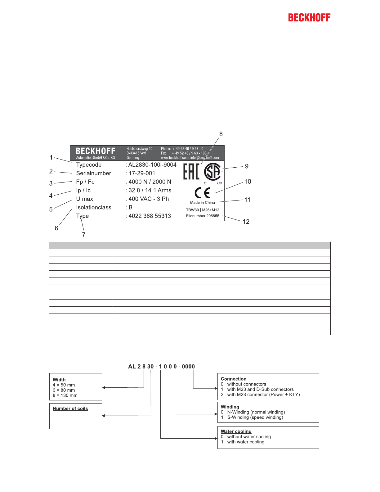
5.2 AL2xxx name plate
Pos. - No. Description
1 Type of the linear motor
2 Serial number
3 Peak force
4 Peak current
5 Max. Voltage
6 Insulation class
7 Type code
8 EAC mark of conformity
9 CSA mark of conformity
10 CE mark of conformity
11 Country of manufacture
12 File number
5.3 AL2xxx type key
Technical description
Linear servomotor AL2xxx 17
Version: 6.2
6 Technical description
6.1 Design of the motors
The linear servomotors from the AL2xxx series are brushless three-phase motors for high-quality servo
applications. In conjunction with our digital servo drives they are particularly suitable for positioning tasks in
industrial robots, machine tools, transfer lines, handling equipment, textile machines, packaging machines,
etc. with high requirements for dynamics and stability. The motors from the AL2xxx series are intended to be
operated exclusively by a digital servo drive with speed and torque control.
The linear servomotors are equipped with permanent magnets in the magnetic plate. This advanced
neodymium magnetic material makes a significant contribution to the motors' exceptional dynamic
properties. A three-phase coil unit supplied by the servo drive is housed in the coil unit. The motor has no
brushes; the commutation being implemented electronically in the servo drive.
Furthermore, a feedback system is necessary for operation. The suitable feedback system must be selected
on the basis of the application requirements. Dynamics, speed, contamination levels, resolution and the
servo drive must be considered (see also the section entitled Magnetic Encoder System (MES) (optional)
[}19]).
6.2 General technical data
Ambient and operating conditions
Climate category 3K3 according to EN 60721
Ambient temperature
(at rated values)
+5 - +40 °C for installation altitudes up to 1000 m amsl
→ see section entitled Power derating
[}17]
Permissible humidity
(at rated values)
95% relative humidity, non-condensing
Installation altitude
(currents and torques)
At installation altitudes of 1000 m or higher above sea level and an ambient
temperature of 40 °C
→ see section entitled Power derating
[}17]
Technical data
→ See section entitled Technical data [}47]
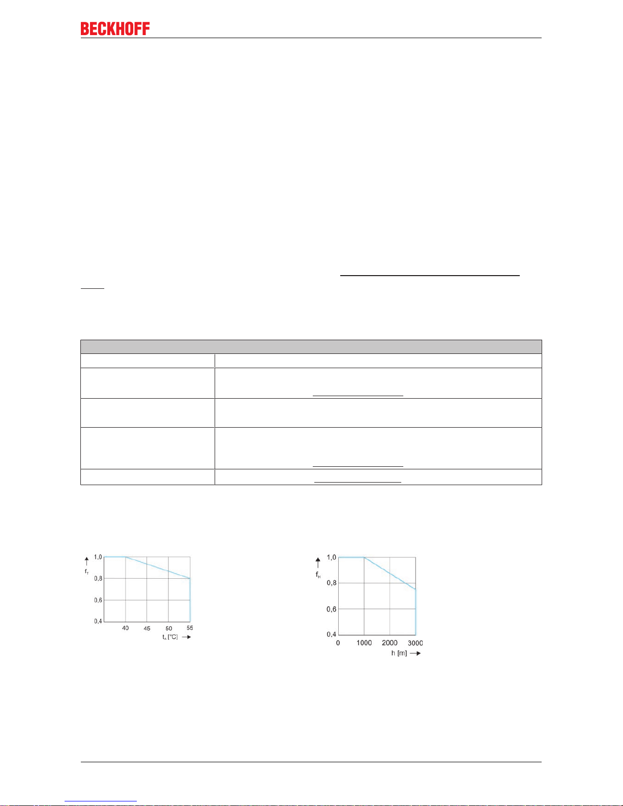
6.2.1 Power derating
Ambient temperature Installation altitude
fT = Temperature
utilization factor
tA = Ambient temperature
°C
fH = Altitude utilization
factor
h = Altitude in meters
Calculation of the power data when exceeding the
specified temperature limit > 40 °C:
F
CA_red
= FCA x f
T
Calculation of the power data when exceeding the
specified installation altitude ≥ 1000 m:
F
CA_red
= FCA x f
H
Calculation of the power data when exceeding the specified limits:
Ambient temperature > 40 °C and installation altitude ≥ 1000 m
F
CA_red
= FCA x fT x f
H
Technical description
Linear servomotor AL2xxx18
Version: 6.2
6.3 Standard features
Machine concept
The AL2xxx linear servomotor series from Beckhoff is not a self-contained
system. It includes various components such as a coil unit and magnetic plates
and must be integrated into a complete machine concept or a complete working
unit.
The size and shape of the carrier frame, the design of the carriage, the type of
rail and type of bearings, and the kind of buffer used depend on the application.
The carrier frame and the carriage must be designed such that an air gap is
created between the coil unit and the magnetic plate.
6.3.1 Coil unit, primary part (N/S)
Winding types
The N-type (normal winding) represents the preferred type. The Stype (speed winding) has a higher maximum speed and a higher
current consumption. The dimensions of the N-type and S-type do not
differ.
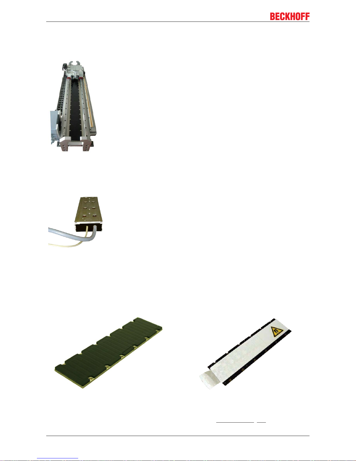
6.3.2 Magnetic plate, secondary part
Magnetic plates are available in various lengths and can be combined with one another as desired within a
series. Different series require magnetic plates with different widths.
Magnetic plate without transport plate Magnetic plate with transport plate
In the delivery condition the magnetic plates are covered by a transport plate. It reduces the magnetic field
and thus enables simple mounting and dismounting.
Specifications and dimensional drawings can be found in the chapter: Technical data [
}47]
 Loading...