


 Loading...
Installation and Operating instructions for
Control Cabinet PCs C63xx -0030 -0040
Version: 1.3
Date: 2011-02-21

Table of contents
Table of contents
1. General instructions |
3 |
Notes on the Documentation |
3 |
Liability Conditions |
3 |
Description of safety symbols |
3 |
Basic safety measures |
4 |
Operator's obligation to exercise diligence |
5 |
Operator requirements |
5 |
2. Product Description |
6 |
Appropriate Use |
6 |
Structure C6320, C6330 |
6 |
Structure C6325, C6335 |
8 |
Structure C6340, C6350 |
10 |
Interfaces |
12 |
USB interfaces |
12 |
Network connection |
12 |
DVI interface |
12 |
USB interface |
12 |
Serial interface |
12 |
Additional plug-in cards (optional) |
12 |
3. Installation Instructions |
13 |
Transport and Unpacking |
13 |
Transport |
13 |
Unpacking |
13 |
Installation of the PC in the control cabinet |
14 |
Power Supply Connection |
15 |
Pin assignment of the connector |
15 |
Fitting the cable |
16 |
Material for assembling the connectors |
16 |
Assembling the connectors |
16 |
Connecting Power Supply |
17 |
Cable Cross Sections |
17 |
PC_ON, Power-Status, UPS output |
17 |
Wiring diagram |
18 |
Connecting devices |
19 |
Connecting cables |
19 |
Check voltage rating and connect |
19 |
4. Operating Instructions |
20 |
Switching the Industrial PC on and off |
20 |
First switching on and driver installation |
20 |
Maintenance |
21 |
Cleaning the Industrial PC |
21 |
Replacing the battery on the motherboard |
21 |
Servicing |
21 |
Shutting down |
21 |
Disposal |
21 |
5. UPS Software Components (optional) |
22 |
Installation on the PC |
22 |
Help files |
22 |
1 |
C63xx |

Table of contents
6. |
Troubleshooting |
23 |
|
Fault correction |
23 |
|
Beckhoff Support & Service |
24 |
|
Beckhoff branches and partner companies |
24 |
|
Beckhoff Headquarters |
24 |
|
Beckhoff Support |
24 |
7. |
Beckhoff Service |
24 |
Assembly dimensions |
25 |
|
8. |
Appendix |
31 |
|
Technical data |
31 |
|
Approvals |
32 |
|
FCC: Federal Communications Commission Radio Frequency Interference |
|
|
Statement |
32 |
|
FCC: Canadian Notice |
32 |
2 |
C63xx |

General instructions
General instructions


 Danger
 Warning
i 
 Note
Note
Notes on the Documentation
This description is only intended for the use of trained specialists in control and automation engineering who are familiar with the applicable national standards. It is essential that the following notes and explanations are followed when installing and commissioning these components.
Liability Conditions
The responsible staff must ensure that the application or use of the products described satisfy all the requirements for safety, including all the relevant laws, regulations, guidelines and standards.
The documentation has been prepared with care. The products described are, however, constantly under development. For that reason the documentation is not in every case checked for consistency with performance data, standards or other characteristics. None of the statements of this manual represents a guarantee (Garantie) in the meaning of § 443 BGB of the German Civil Code or a statement about the contractually expected fitness for a particular purpose in the meaning of § 434 par. 1 sentence 1 BGB. In the event that it contains technical or editorial errors, we retain the right to make alterations at any time and without warning. No claims for the modification of products that have already been supplied may be made on the basis of the data, diagrams and descriptions in this documentation.
© This documentation is copyrighted. Any reproduction or third party use of this publication, whether in whole or in part, without the written permission of Beckhoff Automation GmbH, is forbidden.
Description of safety symbols
The following safety symbols are used in this operating manual. They are intended to alert the reader to the associated safety instructions.
This symbol is intended to highlight risks for the life or health of personnel.
This symbol is intended to highlight risks for equipment, materials or the environment.
This symbol indicates information that contributes to better understanding.
C63xx |
3 |
General instructions
Only switch the PC off after closing the software
Basic safety measures
Before the Industrial PC is switched off, software that is running must be properly closed.
Otherwise it is possible that data on the hard disk is lost. Please read the section on Switching the Industrial PC on and off.
Switch off all parts of the equipment, then uncouple the fieldbus!
 Warning Before opening the housing of the PC, and whenever the PC is being used for purposes other than plant control, such as during functional tests
following repair, all parts of the equipment must first be switched off, after which the Industrial PC can be uncoupled from the plant.
Pulling out the fieldbus connection plug uncouples the PC (optional).
Items of equipment that have been switched off must be secured against being switched on again.
The Industrial PC’s power supply unit must be supplied with 24 VDC.
Do not exchange any parts when under power!
 Danger When components are being fitted or removed, the supply voltage must be switched off.
Fitting work on the Industrial PC can result in damage:
•If metal objects such as screws or tools fall onto operating circuit boards.
•If connecting cables internal to the PC are removed or inserted during operation.
•If plug-in cards are removed or inserted when the PC is switched on.
4 |
C63xx |
General instructions
National regulations depending on the machine type


 Warning
Procedure in the event of a fault
Operator's obligation to exercise diligence
The operator must ensure that
•the Industrial PC is only used for its intended use (see also
Product Description chapter).
•the Industrial PC is in a sound condition and in working order during operation.
•the operation manual is in good condition and complete, and always available for reference at the location of the Industrial PC.
•the Industrial PC is operated, maintained and repaired only by sufficiently qualified and authorized personnel.
•the personnel is instructed regularly about relevant occupational safety and environmental protection aspects, and is familiar with the operating manual and in particular the safety notes contained herein.
•none of the safety and warning notes attached to the Industrial PC are removed, and that all notes remain legible.
Depending on the type of machine and plant in which the Industrial PC is being used, there will be national regulations for the control of such machines and plant that the operator must observe. These regulations cover, amongst other things, the intervals between inspections of the controller.
The operator must initiate such inspections in good time.
Only trained persons may open the Industrial PC housing!
The operator is responsible for ensuring that only trained electrical staff opens the housing of the Industrial PC.
In the event of a fault in the Industrial PC, appropriate measures can be determined with the aid of the list in the Fault correction section.
|
Operator requirements |
Read the operating |
Every user of the Industrial PC must have read these operating |
instructions |
instructions. |
Software knowledge |
Every user must be familiar with any of the functions of the software |
|
installed on the PC that he can reach. |
C63xx |
5 |
Product Description
Product Description
Example: Front view of Industrial PC C6330 in basic configuration
Appropriate Use
The C63xx series Industrial PCs in connection with a DVI / USB-Control- Panel CP68xx or CP78xx are designed for mounting in control cabinets for machine and plant engineering applications.
The PCs of the series C63xx-0030 and C63xx-0040 differ in the configuration of the processor.
Structure C6320, C6330
Configuration with 3 PCI-Slots
1
3 
1 2
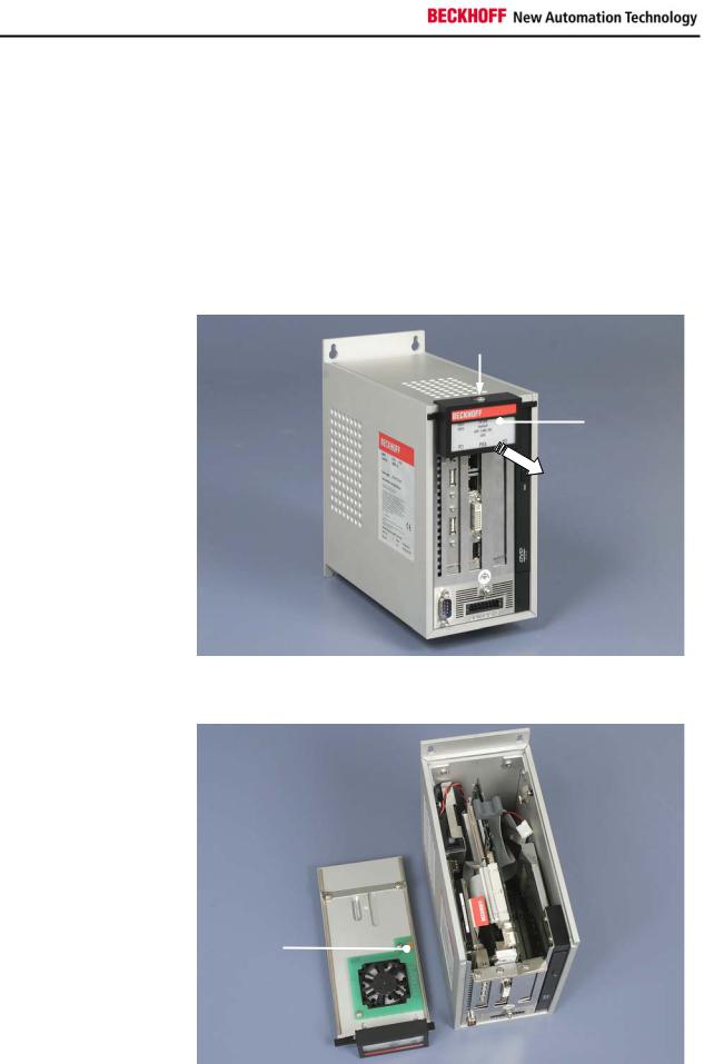
Opening the housing
Top view of the open housing
To open the PC housing, release the screw (1) by one turn using a screwdriver. The plastic cap (2) can be then be pulled forward, thereby releasing the lid (3).
1
The aluminium lid can now be lifted off. Avoid damaging the electrical contacts for the power supply line of the fan (1)!
6 |
C63xx |
Product Description
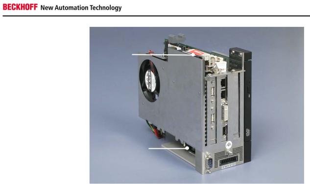
View of the open PC
C6330
2
 3
3
 4
4
1
The computer chassis can now be removed from the housing.
The power supply is located in the lower part of the chassis (1), the 2,5” hard disk is located in the upper part (2).
The slot motherboard (3) is located in the second slot of the housing.
The Slim Line CD-ROM drive (4) is visible right on the picture (only C6330).
C63xx |
7 |

Product Description
Example:
Front view of the C6335 in basic configuration
Structure C6325, C6335
Configuration without fan
1
3 
2
Opening the housing
Top view of the open housing
8
To open the PC housing, release the screw (1) by one turn using a screwdriver. The plastic cap (2) can be then be pulled forward, thereby releasing the lid (3).
1
The aluminium lid can now be lifted off.
The heatsink (1) enables the fanless operation up to an ambient air temperature of 45 oC.
C63xx
Product Description
View of the open PC
C6335
2
 3
3
 4
4
1
The computer chassis can now be removed from the housing.
The power supply is located in the lower part of the chassis (1), the 2,5” hard disk is located in the upper part (2).
The slot motherboard (3) is located in the second slot of the housing.
The Slim Line CD-ROM drive (4) is visible right on the picture (only C6335)
C63xx |
9 |
Loading...