


CB4050
Manual
Revision 3.4
Beckhoff Automation GmbH |
phone: |
+49 (0) 52 46/963-0 |
Eiserstr. 5 |
fax: |
+49 (0) 52 46/963-198 |
33415 Verl |
email: |
info@beckhoff.de |
Germany |
web: |
www.beckhoff.de |
|
|
|
|
Contents |
|
|
|||
Contents |
|
|||
0 |
Document History ................................................................................................................................. |
5 |
||
1 |
Introduction........................................................................................................................................... |
6 |
||
|
1.1 |
Notes on the Documentation......................................................................................................... |
6 |
|
|
1.1.1 |
Liability Conditions ................................................................................................................ |
6 |
|
|
1.1.2 |
Copyright ............................................................................................................................... |
6 |
|
|
1.2 |
Safety Instructions......................................................................................................................... |
7 |
|
|
1.2.1 |
Disclaimer.............................................................................................................................. |
7 |
|
|
1.2.2 |
Description of Safety Symbols .............................................................................................. |
7 |
|
|
1.3 |
Essential Safety Measures............................................................................................................ |
8 |
|
|
1.3.1 |
Operator's Obligation to Exercise Diligence.......................................................................... |
8 |
|
|
1.3.2 |
National Regulations Depending on the Machine Type........................................................ |
8 |
|
|
1.3.3 |
Operator Requirements......................................................................................................... |
8 |
|
|
1.4 |
Functional Range .......................................................................................................................... |
9 |
|
2 |
Overview |
............................................................................................................................................. |
10 |
|
|
2.1 |
Features ...................................................................................................................................... |
10 |
|
|
2.2 |
Specifications and Documents.................................................................................................... |
12 |
|
3 |
Detailed Description ........................................................................................................................... |
13 |
||
|
3.1 |
Power Supply .............................................................................................................................. |
13 |
|
|
3.2 |
CPU |
............................................................................................................................................. |
13 |
|
3.3 |
Memory ....................................................................................................................................... |
13 |
|
4 |
Connectors ......................................................................................................................................... |
14 |
||
|
4.1 |
Connector Map............................................................................................................................ |
15 |
|
|
4.2 |
Power Supply .............................................................................................................................. |
16 |
|
|
4.3 |
System ........................................................................................................................................ |
17 |
|
|
4.4 |
Memory ....................................................................................................................................... |
18 |
|
|
4.5 |
PC/104-Bus ................................................................................................................................. |
21 |
|
|
4.6 |
PC/104-Plus Bus ......................................................................................................................... |
23 |
|
|
4.7 |
VGA |
............................................................................................................................................. |
25 |
|
4.8 |
LCD |
............................................................................................................................................. |
26 |
|
4.9 |
USB 1 to 4, LAN, Sound ............................................................................................................. |
28 |
|
|
4.10 |
IDE Interface ............................................................................................................................... |
30 |
|
|
4.11 |
Parallel Interface LPT.................................................................................................................. |
31 |
|
|
4.12 |
Serial Interface COM1................................................................................................................. |
32 |
|
|
4.13 |
Serial Interface COM2................................................................................................................. |
33 |
|
|
4.14 |
SMBus......................................................................................................................................... |
34 |
|
|
4.15 |
Monitoring Functions ................................................................................................................... |
35 |
|
|
4.16 |
Fan .............................................................................................................................................. |
|
36 |
5 |
BIOS Settings ..................................................................................................................................... |
37 |
||
|
5.1 |
Remarks for Setup Use............................................................................................................... |
37 |
|
|
5.2 |
Top Level Menu........................................................................................................................... |
37 |
|
|
5.3 |
Standard CMOS Features........................................................................................................... |
38 |
|
|
5.3.1 |
IDE Primary Master/Slave................................................................................................... |
39 |
|
|
5.4 |
Advanced BIOS Features ........................................................................................................... |
40 |
|
|
5.4.1 |
CPU Feature ....................................................................................................................... |
42 |
|
|
5.5 |
Advanced Chipset Features........................................................................................................ |
43 |
|
|
5.6 |
Integrated Peripherals ................................................................................................................. |
45 |
|
|
|
|||
Beckhoff New Automation Technology CB4050 |
page 3 |
|||

Contents
|
5.6.1 |
OnChip IDE Devices ........................................................................................................... |
46 |
|
|
5.6.2 |
Onboard Devices................................................................................................................. |
47 |
|
|
5.6.3 |
SuperIO Devices ................................................................................................................. |
48 |
|
|
5.7 |
Power Management Setup.......................................................................................................... |
49 |
|
|
5.8 |
PnP/PCI Configuration ................................................................................................................ |
51 |
|
|
5.8.1 |
IRQ Resources.................................................................................................................... |
52 |
|
|
5.8.2 |
Memory Resources ............................................................................................................. |
53 |
|
|
5.9 |
PC Health Status......................................................................................................................... |
54 |
|
|
5.10 |
Frequency/Voltage Control ......................................................................................................... |
56 |
|
|
5.11 |
Load Fail-Safe Defaults............................................................................................................... |
57 |
|
|
5.12 |
Load Optimized Defaults............................................................................................................. |
57 |
|
|
5.13 |
Set Password .............................................................................................................................. |
57 |
|
|
5.14 |
Save & Exit Setup ....................................................................................................................... |
57 |
|
|
5.15 |
Exit Without Saving ..................................................................................................................... |
57 |
|
6 |
BIOS update ....................................................................................................................................... |
58 |
||
7 |
Mechanical Drawing ........................................................................................................................... |
59 |
||
|
7.1 |
PCB: Dimensions ........................................................................................................................ |
59 |
|
|
7.2 |
PCB: Pin1 Dimensions ................................................................................................................ |
60 |
|
|
7.3 |
PCB: Heatsink Dimensions ......................................................................................................... |
61 |
|
8 |
Technical Data.................................................................................................................................... |
62 |
||
|
8.1 |
Electrical Data ............................................................................................................................. |
62 |
|
|
8.2 |
Environmental Conditions ........................................................................................................... |
62 |
|
|
8.3 |
Thermal Specifications ................................................................................................................ |
63 |
|
9 |
Support and Service ........................................................................................................................... |
64 |
||
|
9.1 |
Beckhoff's Branch Offices and Representatives ......................................................................... |
64 |
|
|
9.2 |
Beckhoff Headquarters................................................................................................................ |
64 |
|
|
9.2.1 |
Beckhoff Support................................................................................................................. |
64 |
|
|
9.2.2 |
Beckhoff Service ................................................................................................................. |
64 |
|
I |
Annex: Post-Codes............................................................................................................................. |
65 |
||
II |
Annex: Resources .............................................................................................................................. |
68 |
||
|
A |
IO Range ......................................................................................................................................... |
68 |
|
|
B |
Memory Range................................................................................................................................ |
68 |
|
|
C |
Interrupt ........................................................................................................................................... |
68 |
|
|
D |
PCI Devices..................................................................................................................................... |
69 |
|
|
E |
SMB Devices................................................................................................................................... |
69 |
|
page 4 |
Beckhoff New Automation Technology CB4050 |

Notes on the Documentation Chapter: Document History
0 |
Document History |
|
|
|
|
|
Revision |
Changes |
0.9 |
|
first AuthorIT-managed version, many changes, e.g.: |
|
|
- new photographs (D5) |
|
|
- "merging" effort between several English versions |
|
|
- new connector symbols |
|
|
- several minor bugs corrected |
|
|
todo: update dimensional drawing |
1.0 |
|
updated PCI table, minor changes |
1.1 |
|
updated dimensional drawings |
3.0 |
|
- new version number (older, pre-AIT versions had already reached 2.x) |
|
|
- added connector map |
|
|
- updated block diagram |
|
|
- updated temperature ranges |
|
|
- several small changes |
3.1 |
|
updated contact details, minor changes |
3.2 |
|
minor changes |
3.3 |
|
added caution note regarding PS_ON, minor changes |
3.4 |
|
improved output quality of dimensional drawings, minor changes |
 NOTE
NOTE
All company names, brand names, and product names referred to in this manual are registered or unregistered trademarks of their respective holders and are, as such, protected by national and international law.
Beckhoff New Automation Technology CB4050 |
page 5 |

Chapter: Introduction |
Notes on the Documentation |
|
|
1 Introduction
1.1 Notes on the Documentation
This description is only intended for the use of trained specialists in control and automation engineering who are familiar with the applicable national standards. It is essential that the following notes and explanations are followed when installing and commissioning these components.
1.1.1 Liability Conditions
The responsible staff must ensure that the application or use of the products described satisfy all the requirements for safety, including all the relevant laws, regulations, guidelines and standards.
The documentation has been prepared with care. The products described are, however, constantly under development. For that reason the documentation is not in every case checked for consistency with performance data, standards or other characteristics. None of the statements of this manual represents a guarantee (Garantie) in the meaning of § 443 BGB of the German Civil Code or a statement about the contractually expected fitness for a particular purpose in the meaning of § 434 par. 1 sentence 1 BGB. In the event that it contains technical or editorial errors, we retain the right to make alterations at any time and without warning. No claims for the modification of products that have already been supplied may be made on the basis of the data, diagrams and descriptions in this documentation.
1.1.2 Copyright
© This documentation is copyrighted. Any reproduction or third party use of this publication, whether in whole or in part, without the written permission of Beckhoff Automation GmbH, is forbidden.
page 6 |
Beckhoff New Automation Technology CB4050 |

Safety Instructions |
Chapter: Introduction |
|
|
1.2 Safety Instructions
Please consider the following safety instructions and descriptions. Product specific safety instructions are to be found on the following pages or in the areas mounting, wiring, commissioning etc.
1.2.1 Disclaimer
All the components are supplied in particular hardware and software configurations appropriate for the application. Modifications to hardware or software configurations other than those described in the documentation are not permitted, and nullify the liability of Beckhoff Automation GmbH.
1.2.2 Description of Safety Symbols
The following safety symbols are used in this documentation. They are intended to alert the reader to the associated safety instructions.
 ACUTE RISK OF INJURY!
If you do not adhere to the safety advise next to this symbol, there is immediate danger to life and health of individuals!
 RISK OF INJURY!
If you do not adhere to the safety advise next to this symbol, there is danger to life and health of individuals!
 HAZARD TO INDIVIDUALS, ENVIRONMENT, DEVICES, OR DATA!
If you do not adhere to the safety advise next to this symbol, there is obvious hazard to individuals, to environment, to materials, or to data.
 NOTE OR POINTER
This symbol indicates information that contributes to better understanding.
Beckhoff New Automation Technology CB4050 |
page 7 |

Chapter: Introduction |
Essential Safety Measures |
|
|
1.3 Essential Safety Measures
1.3.1 Operator's Obligation to Exercise Diligence
The operator must ensure that
o the product is only used for its intended purpose
o the product is only operated in sound condition and in working order
o the instruction manual is in good condition and complete, and always available for reference at the location where the products are used
o the product is only used by suitably qualified and authorised personnel
othe personnel is instructed regularly about relevant occupational safety and environmental protection aspects
othe operating personnel is familiar with the operating manual and in particular the safety notes contained herein
1.3.2 National Regulations Depending on the Machine Type
Depending on the type of machine and plant in which the product is used, national regulations governing the controllers of such machines will apply, and must be observed by the operator. These regulations cover, amongst other things, the intervals between inspections of the controller. The operator must initiate such inspections in good time.
1.3.3 Operator Requirements
o Read the operating instructions
All users of the product must have read the operating instructions for the system they work with. o System know-how
All users must be familiar with all accessible functions of the product.
page 8 |
Beckhoff New Automation Technology CB4050 |

Functional Range |
Chapter: Introduction |
|
|
1.4 Functional Range
 NOTE
NOTE
The descriptions contained in the present documentation represent a detailed and extensive product description. As far as the described motherboard was acquired as an integral component of an Industrial PC from Beckhoff Automation GmbH, this product description shall be applied only in limited scope. Only the contractually agreed specifications of the corresponding Industrial PC from Beckhoff Automation GmbH shall be relevant. Due to several models of Industrial PCs, variations in the component placement of the motherboards are possible. Support and service benefits for the built-in motherboard will be rendered by Beckhoff Automation GmbH exclusively as specified in the product description (inclusive operation system) of the particular Industrial PC.
Beckhoff New Automation Technology CB4050 |
page 9 |
Chapter: Overview |
Features |
|
|
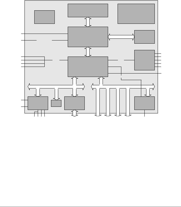
2 Overview
2.1 Features
The CB4050 is a highly complex PC/104-Plus board with the functionalities of a motherboard. Standard features include an Intel® Pentium® M or Intel® Celeron® M CPU, up to 1 GByte RAM (DDR-333) via SO-DIMM200, PCI (PC/104-Plus™) and ISA (PC/104™) bus connectors. The CB4050 also has many additional onboard peripherals: two serial interfaces, one printer interface, floppy connection (via LPT port), LAN connection, Audio in and out, four USB interfaces, CRT and IDE connection.
|
|
|
|
Intel® Pentium® M, |
|
|
|
|
|
|
Power |
|
||
|
|
|
|
Celeron® M |
|
|
|
|
|
|
|
|
||
|
|
Clock |
|
|
|
|
|
VCCCore; VTT; DDRVTT |
|
|||||
|
|
|
|
|
|
|
|
|
|
|||||
|
|
|
|
|
|
|
|
|
|
1,5V; 1,8V; 2,5V; 3,3V |
|
|||
|
|
ICS950813 |
|
|
|
|
|
|
|
|
|
|||
|
|
|
|
HOST |
|
|
|
|
|
|
|
|
|
|
|
|
|
|
|
|
|
|
|
|
|
|
|
|
|
CRT |
|
|
|
|
GMCH |
|
|
|
|
MEMORY |
|
SoDIMM200 |
|
|
|
|
|
|
Intel® 82855GME |
|
|
|
|
DDR333 |
|
||||
LCD |
|
LVDS 18/24/36/48 |
|
|
|
|
|
|
|
|
||||
USB1 |
|
|
|
|
Hub Int |
|
|
|
|
|
|
|
|
SPDIF i |
|
|
|
|
|
|
|
|
|
|
|
|
RealTek® |
SPDIF o |
|
USB2 |
|
|
USB 2.0 |
|
|
|
|
|
|
ACLink |
|
LINE |
||
|
|
|
|
|
|
|
|
|
ALC650/655 |
|||||
USB3 |
|
|
|
|
ICH 4 |
|
|
|
|
|
|
|
MIC |
|
|
|
|
|
|
|
|
|
|
|
|
|
|||
USB4 |
|
|
|
Intel® 82801DB |
|
|
|
|
|
|
|
OUT |
||
|
|
|
|
|
|
|
|
|
|
|
|
|||
|
|
|
|
|
|
|
|
|
|
|
|
|
|
IDE1 |
|
|
|
|
|
|
|
|
|
Intern LAN |
|
|
|
||
|
|
|
LPC |
|
|
|
|
|
|
|
PCI |
|
|
|
KB |
Winbond® |
|
LPC to ISA: |
|
|
|
|
|
|
|
|
Intel® |
|
|
|
BIOS |
W83626 / |
|
|
|
|
|
|
|
|
82551ER/ |
|
||
MS |
W83627HF |
|
|
|
|
|
|
|
|
|
||||
|
F85226F |
|
|
|
|
|
|
|
|
82562EZ |
|
|||
|
|
|
|
|
|
|
|
|
|
|
|
|||
|
COM1 |
COM2 LPT/FDC Watchdog |
|
PC/104 |
PC/104 Plus |
Slot1 |
PC/104 Plus |
Slot2 |
PC/104 Plus |
Slot3 |
PC/104 Plus |
Slot4 |
LAN |
|
o Processor Intel® Celeron® M, Pentium® M o Chipset Intel® 855GME and Intel® ICH4
o SO-DIMM200 socket for up to 1 GByte RAM (DDR-333), capable of ECC o Two serial interfaces COM1 and COM2
o One parallel interface LPT (also for floppy) o Ethernet 10/100 (Base-T)
o IDE interface
o PS2 keyboard / mouse interface o Four USB 2.0 interfaces
o AWARD® BIOS 6.10 o CRT connection
o TFT connection, LVDS 18/24Bit (single and dual pixel displays) o AC97 compatible sound controller with SPDIF in and out
page 10 |
Beckhoff New Automation Technology CB4050 |
Features |
Chapter: Overview |
o RTC with external CMOS battery o 5V single supply voltage
o ISA bus via PC/104 connector
o PCI bus via PC/104-Plus connector o Size 96 mm x 90 (115,5) mm
Beckhoff New Automation Technology CB4050 |
page 11 |

Chapter: Overview |
Specifications and Documents |
|
|
2.2 Specifications and Documents
In making this manual and for further reading of technical documentation, the following documents, specifications and web-pages were used and are recommended.
§ISA specification IEEE996P www.ieee.org
§PC/104™ specification revision 2.5 www.pc104.org
§PC/104-Plus™ specification revision 2.0 www.pc104.org
§PCI specification revision 2.3 resp. 3.0 www.pcisig.com
§ACPI specification revision 3.0 www.acpi.info
§ATA/ATAPI specification version 7 rev. 1 www.t13.org
§USB specifications www.usb.org
§SM-Bus specification revision 2.0 www.smbus.org
§Intel® chipset description 855GM/GME Datasheet, Design Guide www.intel.com
§Intel® chipset description ICH4 Datasheet www.intel.com
§Intel® chip description Celeron® M, Pentium® M www.intel.com
§Winbond® chip description W83627HF, W83626 Datasheet
www.winbond-usa.com oder www.winbond.com.tw
§Fintek® chip description F85226F Datasheet www.fintek.com.tw
§Intel® chip description 82562EZ Datasheet www.intel.com
§Intel® chip description 82551ER Datasheet www.intel.com
§ICS® chip description ICS950813 Datasheet www.icst.com
page 12 |
Beckhoff New Automation Technology CB4050 |

Power Supply |
Chapter: Detailed Description |
|
|
3 Detailed Description
3.1 Power Supply
The power supply of the hardware module is effected via the power connector. The board only requires an operating voltage of 5 volt ± 5%.
3.2 CPU
The board can be ordered with one of the following processors employed: Intel® Celeron® M, Intel® Celeron® M ULV, Intel® Pentium® M. The package type allows a maximum DIE temperature of 100 degrees Celsius and accords highest possible security even in rough environment.
The processors include a second level cache of up to 2 MByte, depending on which model is used. Furthermore the processors offer many features known from the desktop range such as MMX2, serial number, loadable microcode etc.
3.3 Memory
There is one conventional SO-DIMM200 socket available to equip the board with memory. For technical and mechanical reasons it is possible that particular memory modules cannot be employed. Please ask your sales representative for recommended memory modules.
With currently available SO-DIMM200 modules a memory extension up to 1 GByte is possible (DDR-333).
Beckhoff New Automation Technology CB4050 |
page 13 |

Chapter: Connectors |
Memory |
|
|
4 Connectors
This section describes all the connectors found on the CB4050.
 CAUTION
For most interfaces, the cables must meet certain requirements. For instance, USB 2.0 requires twisted and shielded cables to reliably maintain full speed data rates. Restrictions on maximum cable length are also in place for many high speed interfaces and for power supply. Please refer to the respective specifications and use suitable cables at all times.
page 14 |
Beckhoff New Automation Technology CB4050 |

Connector Map |
Chapter: Connectors |
|
|
4.1 Connector Map
Please use the connector map below for quick reference. Only connectors on the component side are shown. For more information on each connector refer to the table below.
Ref-No. |
Function |
Page |
P401 |
"Fan" |
p. 36 |
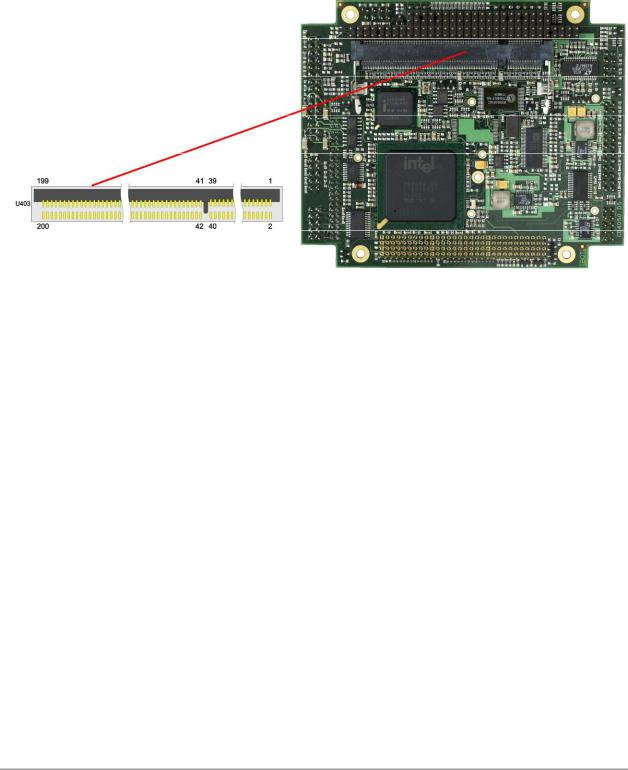
U403* |
"Memory" |
p. 18 |
P700 |
"Serial Interface COM1" |
p. 32 |
P702 |
"Parallel Interface LPT" |
p. 31 |
P703 |
"Serial Interface COM2" |
p. 33 |
P704 |
"IDE Interface" |
p. 30 |
P705 |
"USB 1 to 4, LAN, Sound" |
p. 28 |
P706/7 |
"LCD" |
p. 26 |
P1001 |
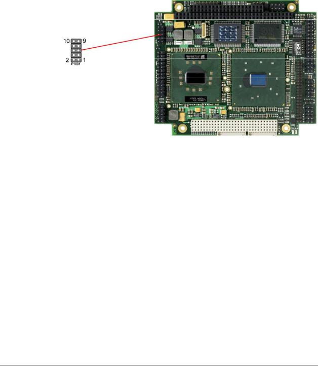
"System" |
p. 17 |
P1002/6 |
"PC/104-Bus" |
p. 21 |
P1003 |
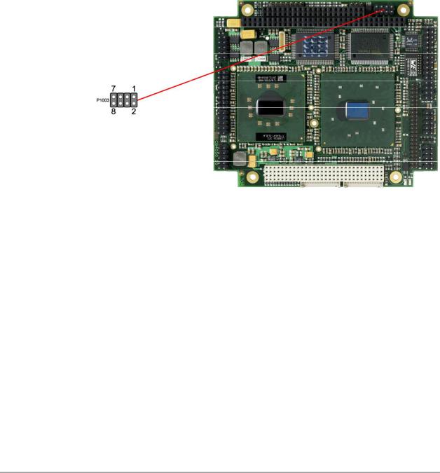
"Power Supply" |
p. 16 |
P1004 |
"PC/104-Plus Bus" |
p. 23 |
P1005 |
"VGA" |
p. 25 |
P1007 |
"SMBus" |
p. 34 |
P1008 |
"Monitoring Functions" |
p. 35 |
* not in the picture above (cf. bottom side of board)
Beckhoff New Automation Technology CB4050 |
page 15 |
Chapter: Connectors |
Power Supply |
|
|
4.2 Power Supply
The connector for the power supply is a standard IDC socket connector with a spacing of 2.54 mm. The board only requires an operating voltage of 5 volt ± 5%. 3.3V output to the PC/104-Plus bus is the only off-board supply available.
Should additional voltages be needed for PC/104 expansion cards, these must be provided externally by connecting the respective pins (see below).
For maximum current availability, it is recommended to use both this power connector and the PC/104 connector for power supply.
 NOTE
NOTE
For "Real Time Clock" an external battery (3.3V) must be connected. You can use pins 1 & 3 here or the "System" connector (see next page).
Description |
Name |
|
Pin |
Name |
Description |
|
ground |
GND |
1 |
|
2 |
VCC |
5 volt supply |
CMOS battery >= 3 volt |
VBAT |
3 |
|
4 |
12V |
12 volt supply |
-5 volt supply |
-5V |
5 |
|
6 |
-12V |
-12 volt supply |
ground |
GND |
7 |
|
8 |
VCC |
5 volt supply |
page 16 |
Beckhoff New Automation Technology CB4050 |
System |
Chapter: Connectors |
|
|
4.3 System
The system connector, which has the main functions that are necessary to start the board, is provided via a standard IDC socket connector with a spacing of 2.54 mm.
This connector supports the following interfaces: PS/2 keyboard, PS/2 mouse, speaker, external RTC-battery and reset of the board.
 NOTE
NOTE
For "Real Time Clock" an external battery (3.3V) must be connected. Connect "+" to VBAT and "-" to GND.
Description |
Name |
|
Pin |
Name |
Description |
|
speaker to 5 volt |
SPEAKER |
1 |
|
2 |
GND |
ground |
reset to ground |
RESET# |
3 |
|
4 |
KLOCK# |
keyboard lock |
keyboard Data |
KDAT |
5 |
|
6 |
KCLK |
keyboard clock |
mouse data |
MDAT |
7 |
|
8 |
MCLK |
mouse clock |
CMOS battery ≥ 3 volt |
VBAT |
9 |
|
10 |
VCC |
5 volt supply |
Beckhoff New Automation Technology CB4050 |
page 17 |
Chapter: Connectors |
Memory |
|
|
4.4 Memory
There is one conventional SO-DIMM200 socket available to equip the board with memory (DDR-333). It is located on the bottom side of the board. For technical and mechanical reasons it is possible that particular memory modules cannot be employed. Please ask your sales representative for recommended memory modules.
With currently available SO-DIMM modules a memory extension up to 1 GByte is possible. The timing parameters for different memory modules are automatically set by BIOS.
Description |
Name |
|
Pin |
Name |
Description |
|
memory reference current |
REF |
1 |
|
2 |
REF |
memory reference current |
ground |
GND |
3 |
|
4 |
GND |
ground |
data 0 |
DQ0 |
5 |
|
6 |
DQ4 |
data 4 |
data 1 |
DQ1 |
7 |
|
8 |
DQ5 |
data 5 |
2.5 volt supply |
2.5V |
9 |
|
10 |
2.5V |
2.5 volt supply |
data strobe 0 |
DQS0 |
11 |
|
12 |
DQM0 |
data mask 0 |
data 2 |
DQ2 |
13 |
|
14 |
DQ6 |
data 6 |
ground |
GND |
15 |
|
16 |
GND |
ground |
data 3 |
DQ3 |
17 |
|
18 |
DQ7 |
data 7 |
data 8 |
DQ8 |
19 |
|
20 |
DQ12 |
data 12 |
2.5 volt supply |
2.5V |
21 |
|
22 |
2.5V |
2.5 volt supply |
data 9 |
DQ9 |
23 |
|
24 |
DQ13 |
data 13 |
data strobe 1 |
DQS1 |
25 |
|
26 |
DQM1 |
data mask 1 |
ground |
GND |
27 |
|
28 |
GND |
ground |
data 10 |
DQ10 |
29 |
|
30 |
DQ14 |
data 14 |
data 11 |
DQ11 |
31 |
|
32 |
DQ15 |
data 15 |
2.5 volt supply |
2.5V |
33 |
|
34 |
2.5V |
2.5 volt supply |
clock |
CK0 |
35 |
|
36 |
2.5V |
2.5 volt supply |
clock |
CK0# |
37 |
|
38 |
2.5V |
2.5 volt supply |
ground |
GND |
39 |
|
40 |
GND |
ground |
data 16 |
DQ16 |
41 |
|
42 |
DQ20 |
data 20 |
data 17 |
DQ17 |
43 |
|
44 |
DQ21 |
data 21 |
2.5 volt supply |
2.5V |
45 |
|
46 |
2.5V |
2.5 volt supply |
data strobe 2 |
DQS2 |
47 |
|
48 |
DQM2 |
data mask 2 |
data 18 |
DQ18 |
49 |
|
50 |
DQ22 |
data 22 |
page 18 |
Beckhoff New Automation Technology CB4050 |

Memory |
|
|
|
|
|
Chapter: Connectors |
|
|
|
|
|
|
|
|
|
|
|
|
|
|
Description |
Name |
|
Pin |
Name |
Description |
|
ground |
GND |
51 |
|
52 |
GND |
ground |
data 19 |
DQ19 |
53 |
|
54 |
DQ23 |
data 23 |
data 24 |
DQ24 |
55 |
|
56 |
DQ28 |
data 28 |
2.5 volt supply |
2.5V |
57 |
|
58 |
2.5V |
2.5 volt supply |
data 25 |
DQ25 |
59 |
|
60 |
DQ29 |
data 29 |
data strobe 3 |
DQS3 |
61 |
|
62 |
DQM3 |
data mask 3 |
ground |
GND |
63 |
|
64 |
GND |
ground |
data 26 |
DQ26 |
65 |
|
66 |
DQ30 |
data 30 |
data 27 |
DQ27 |
67 |
|
68 |
DQ31 |
data 31 |
2.5 volt supply |
2.5V |
69 |
|
70 |
2.5V |
2.5 volt supply |
data check bit 0 |
CB0 |
71 |
|
72 |
CB4 |
data check bit 4 |
data check bit 1 |
CB1 |
73 |
|
74 |
CB5 |
data check bit 5 |
ground |
GND |
75 |
|
76 |
GND |
ground |
data strobe 8 |
DQS8 |
77 |
|
78 |
DQM8 |
data mask 8 |
data check bit 2 |
CB2 |
79 |
|
80 |
CB6 |
data check bit 6 |
2.5 volt supply |
2.5V |
81 |
|
82 |
2.5V |
2.5 volt supply |
data check bit 3 |
CB3 |
83 |
|
84 |
CB7 |
data check bit 7 |
reserved |
N/C |
85 |
|
86 |
N/C |
reserved |
ground |
GND |
87 |
|
88 |
GND |
ground |
clock |
CK2 |
89 |
|
90 |
GND |
ground |
clock |
CK2# |
91 |
|
92 |
2.5V |
2.5 volt supply |
2.5 volt supply |
2.5V |
93 |
|
94 |
2.5V |
2.5 volt supply |
clock enables 1 |
CKE1 |
95 |
|
96 |
CKE0 |
clock enables 0 |
reserved |
N/C |
97 |
|
98 |
N/C |
reserved |
address 12 |
A12 |
99 |
|
100 |
A11 |
address 11 |
address 9 |
A9 |
101 |
|
102 |
A8 |
address 8 |
ground |
GND |
103 |
|
104 |
GND |
ground |
address 7 |
A7 |
105 |
|
106 |
A6 |
address 6 |
address 5 |
A5 |
107 |
|
108 |
A4 |
address 4 |
address 3 |
A3 |
109 |
|
110 |
A2 |
address 2 |
address 1 |
A1 |
111 |
|
112 |
A0 |
address 0 |
2.5 volt supply |
2.5V |
113 |
|
114 |
2.5V |
2.5 volt supply |
address 10 |
A10 |
115 |
|
116 |
BA1 |
SDRAM bank 1 |
SDRAM bank 0 |
BA0 |
117 |
|
118 |
RAS# |
row address strobe |
write enable |
WE# |
119 |
|
120 |
CAS# |
column address strobe |
chip select |
S0# |
121 |
|
122 |
S1# |
chip select |
reserved |
N/C |
123 |
|
124 |
N/C |
reserved |
ground |
GND |
125 |
|
126 |
GND |
ground |
data 32 |
DQ32 |
127 |
|
128 |
DQ36 |
data 36 |
data 33 |
DQ33 |
129 |
|
130 |
DQ37 |
data 37 |
2.5 volt supply |
2.5V |
131 |
|
132 |
2.5V |
2.5 volt supply |
data strobe 4 |
DQS4 |
133 |
|
134 |
DQM4 |
data mask 4 |
data 34 |
DQ34 |
135 |
|
136 |
DQ38 |
data 38 |
ground |
GND |
137 |
|
138 |
GND |
ground |
data 35 |
DQ35 |
139 |
|
140 |
DQ39 |
data 39 |
data 40 |
DQ40 |
141 |
|
142 |
DQ44 |
data 44 |
2.5 volt supply |
2.5V |
143 |
|
144 |
2.5V |
2.5 volt supply |
data 41 |
DQ41 |
145 |
|
146 |
DQ45 |
data 45 |
data strobe 5 |
DQS5 |
147 |
|
148 |
DQM5 |
data mask 5 |
ground |
GND |
149 |
|
150 |
GND |
ground |
data 42 |
DQ42 |
151 |
|
152 |
DQ46 |
data 46 |
data 43 |
DQ43 |
153 |
|
154 |
DQ47 |
data 47 |
2.5 volt supply |
2.5V |
155 |
|
156 |
2.5V |
2.5 volt supply |
2.5 volt supply |
2.5V |
157 |
|
158 |
CK1# |
clock |
ground |
GND |
159 |
|
160 |
CK1 |
clock |
Beckhoff New Automation Technology CB4050 |
page 19 |

Chapter: Connectors |
|
|
|
|
|
Memory |
|
|
|
|
|
|
|
|
|
|
|
|
|
|
Description |
Name |
|
Pin |
Name |
Description |
|
ground |
GND |
161 |
|
162 |
GND |
ground |
data 48 |
DQ48 |
163 |
|
164 |
DQ52 |
data 52 |
data 49 |
DQ49 |
165 |
|
166 |
DQ53 |
data 53 |
2.5 volt supply |
2.5V |
167 |
|
168 |
2.5V |
2.5 volt supply |
data strobe 6 |
DQS6 |
169 |
|
170 |
DQM6 |
data mask 6 |
data 50 |
DQ50 |
171 |
|
172 |
DQ54 |
data 54 |
ground |
GND |
173 |
|
174 |
GND |
ground |
data 51 |
DQ51 |
175 |
|
176 |
DQ55 |
data 55 |
data 56 |
DQ56 |
177 |
|
178 |
DQ60 |
data 60 |
2.5 volt supply |
2.5V |
179 |
|
180 |
2.5V |
2.5 volt supply |
data 57 |
DQ57 |
181 |
|
182 |
DQ61 |
data 61 |
data strobe 7 |
DQS7 |
183 |
|
184 |
DQM7 |
data mask 7 |
ground |
GND |
185 |
|
186 |
GND |
ground |
data 58 |
DQ58 |
187 |
|
188 |
DQ62 |
data 62 |
data 59 |
DQ59 |
189 |
|
190 |
DQ63 |
data 63 |
2.5 volt supply |
2.5V |
191 |
|
192 |
2.5V |
2.5 volt supply |
SPD data |
SDA |
193 |
|
194 |
SA0 |
SPD address |
SPD clock |
SCL |
195 |
|
196 |
SA1 |
SPD address |
3.3 volt supply |
3.3V |
197 |
|
198 |
SA2 |
SPD address |
reserved |
N/C |
199 |
|
200 |
N/C |
reserved |
page 20 |
Beckhoff New Automation Technology CB4050 |
PC/104-Bus Chapter: Connectors
4.5 PC/104-Bus
An onboard LPC-to-ISA bridge (Fintek® F85226F) makes it possible to expand the functionality of the board with additional PC/104 cards. This interface offers full 16bit ISA compliance. For further information on this interface please refer to the PC/104 specifications (see "Specifications and Documents", p. 12).
Pinning of the standard 8 bit PC/104 connector.
Description |
Name |
|
Pin |
Name |
Description |
|
ISA - IO channel check |
IOCHK# |
A1 |
|
B1 |
GND |
ground |
ISA – data 7 |
SD7 |
A2 |
|
B2 |
RSTDRV |
reset drive |
ISA – data 6 |
SD6 |
A3 |
|
B3 |
VCC |
5 volt supply |
ISA – data 5 |
SD5 |
A4 |
|
B4 |
IRQ9 |
ISA – interrupt 9 (2) |
ISA – data 4 |
SD4 |
A5 |
|
B5 |
-5V |
-5 volt supply |
ISA – data 3 |
SD3 |
A6 |
|
B6 |
DRQ2 |
ISA – DMA request 2 |
ISA – data 2 |
SD2 |
A7 |
|
B7 |
-12V |
-12 volt supply |
ISA – data 1 |
SD1 |
A8 |
|
B8 |
IOCHRDY |
ISA – IO channel ready |
ISA – data 0 |
SD0 |
A9 |
|
B9 |
12V |
12 volt supply |
ISA – IO channel ready |
IOCHRDY |
A10 |
|
B10 |
N/C |
reserved |
ISA – address enable |
AEN |
A11 |
|
B11 |
SMEMW# |
ISA – system memory write |
ISA – address 19 |
SA19 |
A12 |
|
B12 |
SMEMR# |
ISA – system memory read |
ISA – address 18 |
SA18 |
A13 |
|
B13 |
IOW# |
ISA – IO write |
ISA – address 17 |
SA17 |
A14 |
|
B14 |
IOR# |
ISA – IO read |
ISA – address 16 |
SA16 |
A15 |
|
B15 |
DACK3# |
ISA – DMA acknowledge 3 |
ISA – address 15 |
SA15 |
A16 |
|
B16 |
DRQ3 |
ISA – DMA request 3 |
ISA – address 14 |
SA14 |
A17 |
|
B17 |
DACK1# |
ISA – DMA acknowledge 1 |
ISA – address 13 |
SA13 |
A18 |
|
B18 |
DRQ1 |
ISA – DMA request 1 |
ISA – address 12 |
SA12 |
A19 |
|
B19 |
REFRESH# |
ISA – refresh |
ISA – address 11 |
SA11 |
A20 |
|
B20 |
SYSCLK |
ISA – system clock |
ISA – address 10 |
SA10 |
A21 |
|
B21 |
IRQ7 |
ISA – interrupt 7 |
ISA – address 9 |
SA9 |
A22 |
|
B22 |
IRQ6 |
ISA – interrupt 6 |
ISA – address 8 |
SA8 |
A23 |
|
B23 |
IRQ5 |
ISA – interrupt 5 |
ISA – address 7 |
SA7 |
A24 |
|
B24 |
IRQ4 |
ISA – interrupt 4 |
ISA – address 6 |
SA6 |
A25 |
|
B25 |
IRQ3 |
ISA – interrupt 3 |
ISA – address 5 |
SA5 |
A26 |
|
B26 |
DACK2# |
ISA – DMA acknowledge 2 |
ISA – address 4 |
SA4 |
A27 |
|
B27 |
T/C |
ISA – terminal count |
ISA – address 3 |
SA3 |
A28 |
|
B28 |
BALE |
ISA – address latch en. |
|
|
|
|
|
|
|
Beckhoff New Automation Technology CB4050 |
page 21 |
 Loading...