


CB2051
Manual
rev 1.1
Beckhoff Automation GmbH |
phone: |
+49 (0) 52 46/963-0 |
Eiserstr. 5 |
fax: |
+49 (0) 52 46/963-198 |
33415 Verl |
email: |
info@beckhoff.de |
Germany |
web: |
www.beckhoff.de |
|
|
|
Contents |
|
|
||
Contents |
|
||
0 |
Document History ........................................................................................................................... |
5 |
|
1 |
Introduction..................................................................................................................................... |
6 |
|
|
1.1 |
Notes on the Documentation .................................................................................................. |
6 |
|
1.1.1 |
Liability Conditions ............................................................................................................. |
6 |
|
1.1.2 |
Copyright ........................................................................................................................... |
6 |
|
1.2 |
Safety Instructions.................................................................................................................. |
7 |
|
1.2.1 |
Disclaimer .......................................................................................................................... |
7 |
|
1.2.2 Description of Safety Symbols............................................................................................ |
7 |
|
|
1.3 |
Essential Safety Measures ..................................................................................................... |
8 |
|
1.3.1 Operator's Obligation to Exercise Diligence ........................................................................ |
8 |
|
|
1.3.2 National Regulations Depending on the Machine Type ....................................................... |
8 |
|
|
1.3.3 |
Operator Requirements...................................................................................................... |
8 |
|
1.4 |
Functional Range ................................................................................................................... |
9 |
2 |
Overview ...................................................................................................................................... |
10 |
|
|
2.1 |
Features............................................................................................................................... |
10 |
|
2.2 |
Specifications and Documents.............................................................................................. |
12 |
3 |
Connectors ................................................................................................................................... |
13 |
|
|
3.1 |
Power Supply ....................................................................................................................... |
13 |
|
3.2 |
CMOS battery ...................................................................................................................... |
14 |
|
3.3 |
System................................................................................................................................. |
15 |
|
3.4 |
PISA Slot.............................................................................................................................. |
16 |
|
3.5 |
Mini-PCI ............................................................................................................................... |
19 |
|
3.6 |
Memory................................................................................................................................ |
21 |
|
3.7 |
SATA Interfaces ................................................................................................................... |
24 |
|
3.8 |
IDE interface ........................................................................................................................ |
25 |
|
3.9 |
Floppy interface.................................................................................................................... |
26 |
|
3.10 |
USB, Keyboard/Mouse ......................................................................................................... |
27 |
|
3.11 |
Serial Interfaces COM1 & COM2 .......................................................................................... |
29 |
|
3.12 |
Serial Interfaces COM3 & COM4 .......................................................................................... |
30 |
|
3.13 |
VGA/DVI .............................................................................................................................. |
31 |
|
3.14 |
LVDS ................................................................................................................................... |
32 |
|
3.15 |
LAN1.................................................................................................................................... |
34 |
|
3.16 |
LAN2.................................................................................................................................... |
35 |
|
3.17 |
Touch Screen....................................................................................................................... |
36 |
|
3.18 |
Audio.................................................................................................................................... |
37 |
|
3.19 |
GPIO.................................................................................................................................... |
38 |
|
3.20 |
SMB/I2C............................................................................................................................... |
39 |
|
3.21 |
Fan Connectors.................................................................................................................... |
40 |
4 |
BIOS Settings............................................................................................................................... |
41 |
|
|
4.1 |
Remarks for Setup Use ........................................................................................................ |
41 |
|
4.2 |
Top Level Menu.................................................................................................................... |
41 |
|
4.3 |
Standard CMOS Features .................................................................................................... |
42 |
|
4.3.1 |
IDE Channel 0 Master/Slave ............................................................................................ |
44 |
|
4.3.2 |
SATA channels ................................................................................................................ |
45 |
|
4.4 |
Advanced BIOS Features ..................................................................................................... |
46 |
|
4.4.1 |
CPU Feature.................................................................................................................... |
48 |
|
|
||
Beckhoff New Automation Technology CB2051 |
page 3 |
||

Contents
|
4.4.2 Hard Disk Boot Priority ..................................................................................................... |
49 |
|
4.5 |
Advanced Chipset Features.................................................................................................. |
50 |
|
|
4.5.1 PCI Express Root Port Function ....................................................................................... |
52 |
|
4.6 |
Integrated Peripherals .......................................................................................................... |
53 |
|
|
4.6.1 |
OnChip IDE Devices ........................................................................................................ |
54 |
|
4.6.2 |
Onboard Devices ............................................................................................................. |
55 |
|
4.6.3 |
SuperIO Devices.............................................................................................................. |
56 |
4.7 |
Power Management Setup ................................................................................................... |
58 |
|
4.8 |
PnP/PCI Configuration.......................................................................................................... |
60 |
|
|
4.8.1 |
IRQ Resources................................................................................................................. |
61 |
4.9 |
PC Health Status.................................................................................................................. |
62 |
|
4.10 |
Frequency/Voltage Control ................................................................................................... |
64 |
|
4.11 |
Load Fail-Safe Defaults ........................................................................................................ |
65 |
|
4.12 |
Load Optimized Defaults ...................................................................................................... |
65 |
|
4.13 |
Set Password ....................................................................................................................... |
65 |
|
4.14 |
Save & Exit Setup ................................................................................................................ |
65 |
|
4.15 |
Exit Without Saving .............................................................................................................. |
65 |
|
5 |
BIOS update................................................................................................................................. |
66 |
|
6 |
Mechanical Drawing...................................................................................................................... |
67 |
|
6.1 |
PCB: Mounting Holes ........................................................................................................... |
67 |
|
6.2 |
PCB: Pin1 Dimensions ......................................................................................................... |
68 |
|
6.3 |
PCB: Die Center................................................................................................................... |
69 |
|
7 |
Technical Data.............................................................................................................................. |
70 |
|
7.1 |
Electrical Data ...................................................................................................................... |
70 |
|
7.2 |
Environmental Conditions..................................................................................................... |
70 |
|
7.3 |
Thermal Specifications ......................................................................................................... |
71 |
|
8 |
Support and Service ..................................................................................................................... |
72 |
|
8.1 |
Beckhoff's Branch Offices and Representatives.................................................................... |
72 |
|
8.2 |
Beckhoff Headquarters......................................................................................................... |
72 |
|
|
8.2.1 |
Beckhoff Support.............................................................................................................. |
72 |
|
8.2.2 |
Beckhoff Service .............................................................................................................. |
72 |
I |
Annex: Post-Codes....................................................................................................................... |
73 |
|
II |
Annex: Resources ........................................................................................................................ |
76 |
|
A |
IO Range.................................................................................................................................. |
76 |
|
B |
Memory Range......................................................................................................................... |
76 |
|
C |
Interrupt.................................................................................................................................... |
76 |
|
D |
PCI Devices.............................................................................................................................. |
77 |
|
E |
SMB Devices............................................................................................................................ |
77 |
|
page 4 |
Beckhoff New Automation Technology CB2051 |

Notes on the Documentation Chapter: Document History
0 |
Document History |
|
|
|
|
|
Version |
Changes |
0.1 |
|
first pre-release |
0.2 |
|
dimensional drawings added |
1.0 |
|
updated contact details, minor changes |
1.1 |
|
minor changes |
 NOTE
NOTE
All company names, brand names, and product names referred to in this manual are registered or unregistered trademarks of their respective holders and are, as such, protected by national and international law.
Beckhoff New Automation Technology CB2051 |
page 5 |

Chapter: Introduction |
Notes on the Documentation |
|
|
1 Introduction
1.1 Notes on the Documentation
This description is only intended for the use of trained specialists in control and automation engineering who are familiar with the applicable national standards. It is essential that the following notes and explanations are followed when installing and commissioning these components.
1.1.1 Liability Conditions
The responsible staff must ensure that the application or use of the products described satisfy all the requirements for safety, including all the relevant laws, regulations, guidelines and standards.
The documentation has been prepared with care. The products described are, however, constantly under development. For that reason the documentation is not in every case checked for consistency with performance data, standards or other characteristics. None of the statements of this manual represents a guarantee (Garantie) in the meaning of § 443 BGB of the German Civil Code or a statement about the contractually expected fitness for a particular purpose in the meaning of § 434 par. 1 sentence 1 BGB. In the event that it contains technical or editorial errors, we retain the right to make alterations at any time and without warning. No claims for the modification of products that have already been supplied may be made on the basis of the data, diagrams and descriptions in this documentation.
1.1.2 Copyright
© This documentation is copyrighted. Any reproduction or third party use of this publication, whether in whole or in part, without the written permission of Beckhoff Automation GmbH, is forbidden.
page 6 |
Beckhoff New Automation Technology CB2051 |

Safety Instructions |
Chapter: Introduction |
|
|
1.2 Safety Instructions
Please consider the following safety instructions and descriptions. Product specific safety instructions are to be found on the following pages or in the areas mounting, wiring, commissioning etc.
1.2.1 Disclaimer
All the components are supplied in particular hardware and software configurations appropriate for the application. Modifications to hardware or software configurations other than those described in the documentation are not permitted, and nullify the liability of Beckhoff Automation GmbH.
1.2.2 Description of Safety Symbols
The following safety symbols are used in this documentation. They are intended to alert the reader to the associated safety instructions.
 ACUTE RISK OF INJURY!
If you do not adhere to the safety advise next to this symbol, there is immediate danger to life and health of individuals!
 RISK OF INJURY!
If you do not adhere to the safety advise next to this symbol, there is danger to life and health of individuals!
 HAZARD TO INDIVIDUALS, ENVIRONMENT, DEVICES, OR DATA!
If you do not adhere to the safety advise next to this symbol, there is obvious hazard to individuals, to environment, to materials, or to data.
 NOTE OR POINTER
This symbol indicates information that contributes to better understanding.
Beckhoff New Automation Technology CB2051 |
page 7 |

Chapter: Introduction |
Essential Safety Measures |
|
|
1.3 Essential Safety Measures
1.3.1 Operator's Obligation to Exercise Diligence
The operator must ensure that
o the product is only used for its intended purpose
o the product is only operated in sound condition and in working order
o the instruction manual is in good condition and complete, and always available for reference at the location where the products are used
o the product is only used by suitably qualified and authorised personnel
othe personnel is instructed regularly about relevant occupational safety and environmental protection aspects
othe operating personnel is familiar with the operating manual and in particular the safety notes contained herein
1.3.2 National Regulations Depending on the Machine Type
Depending on the type of machine and plant in which the product is used, national regulations governing the controllers of such machines will apply, and must be observed by the operator. These regulations cover, amongst other things, the intervals between inspections of the controller. The operator must initiate such inspections in good time.
1.3.3 Operator Requirements
o Read the operating instructions
All users of the product must have read the operating instructions for the system they work with. o System know-how
All users must be familiar with all accessible functions of the product.
page 8 |
Beckhoff New Automation Technology CB2051 |

Functional Range |
Chapter: Introduction |
|
|
1.4 Functional Range
 NOTE
NOTE
The descriptions contained in the present documentation represent a detailed and extensive product description. As far as the described motherboard was acquired as an integral component of an Industrial PC from Beckhoff Automation GmbH, this product description shall be applied only in limited scope. Only the contractually agreed specifications of the corresponding Industrial PC from Beckhoff Automation GmbH shall be relevant. Due to several models of Industrial PCs, variations in the component placement of the motherboards are possible. Support and service benefits for the built-in motherboard will be rendered by Beckhoff Automation GmbH exclusively as specified in the product description (inclusive operation system) of the particular Industrial PC.
Beckhoff New Automation Technology CB2051 |
page 9 |
Chapter: Overview |
Features |
|
|
2 Overview
2.1 Features
The CB2051 is a computer motherboard for industrial applications. It complies with the PISA-Slot form factor and ships with either Intel® Celeron® M, Intel® Core™ Duo or Intel® Core™2 Duo CPUs. Two SODIMM200 slots allow a maximum of 2 GByte DDR2-667 RAM. The CB2051 offers a high degree of flexibility in terms of connecting external devices to the board. In addition to the ISA and PCI busses being available through the PISA connector there is also a MiniPCI connector. Furthermore we have two SATA channels and one IDE channel, four serial ports, two LAN connectors, several analog and digital sound inand outputs, eight USB ports, CRT and LCD connectors.
|
|
|
|
|
Intel® Core™2 Duo, |
|
|
Power |
|
|
|
|
|
|
Core™ Duo, Celeron® M |
|
|
|
|
|
|
Clock |
|
|
|
VCCCore; VTT; DDRVTT |
|
||
|
|
|
|
|
|
|
|||
|
|
|
|
|
|
1,5V; 1,8V; 2,5V; 3,3V |
|
||
|
|
IDTCV111PAG |
|
|
|
|
|
||
|
|
|
|
HOST |
|
|
|
|
|
|
|
|
|
|
|
|
|
|
|
CRT |
|
|
|
|
|
|
|
2x |
|
LCD |
|
LVDS 18 |
|
|
GMCH |
|
|
|
|
|
|
|
|
|
|
|
|||
|
|
|
|
|
Intel® 945GM(E) |
|
MEMORY (Dual Ch.) |
SoDIMM200 |
|
USB1 |
|
|
|
|
|
|
DDR2-667 |
|
|
|
|
|
|
|
|
|
|
|
|
USB2 |
|
|
|
|
|
|
|
|
SMBus |
USB3 |
|
|
|
|
|
|
|
|
|
|
|
|
|
DMI |
|
|
|
SPDIF i |
|
USB4 |
|
|
|
|
|
|
|
||
USB5 |
|
|
|
|
|
|
|
|
SPDIF o |
USB6 |
|
USB 2.0 |
|
|
|
|
|
RealTek® |
LINE IN |
USB7 |
|
|
|
|
|
ACLink |
ALC655 |
LINE OUT |
|
|
|
|
|
ICH7R |
|
||||
USB8 |
|
|
|
|
|
|
|
MIC |
|
|
|
Intel® |
|
Intel® 82801GB(M) |
|
|
|
AUX |
|
|
|
PCIe |
|
|
|
CD IN |
|||
|
|
82573E |
|
|
|
|
|
||
|
|
|
|
|
|
|
|
IDE |
|
|
|
|
|
|
|
|
|
|
|
LAN2 |
|
|
|
|
|
|
|
|
SATA1 |
|
|
|
|
|
|
|
|
|
SATA2 |
BIOS |
|
|
LPC |
|
|
|
|
|
|
|
|
|
|
|
|
|
PCI |
|
|
KB |
|
Winbond® |
Winbond® |
Fintek® |
|
|
Intel® |
|
|
MS |
|
|
|
LAN1 |
|||||
W83627HG |
W83627HG |
F85226E |
|
|
82562GZ |
||||
I2C |
|
|
|
||||||
|
|
|
|
|
|
|
|
|
|
FAN 1 |
FAN 2 |
LPT/FDC COM1 COM2 Watchdog |
COM3 COM4 |
16x GPIO |
ISA (PISA) |
PCI (mPCI) |
PCI (PISA) |
|
|
o Processor Intel® Celeron® M, Intel® Core™ Duo or Intel® Core™2 Duo o Chipset Intel® 945GM and Intel® ICH7
o Two SO-DIMM200 slots for up to 2 GByte DDR2-667 o Four serial ports COM1 to COM4
o LAN Ethernet 10/100 (Base-T)
o LAN Ethernet 10/100/1000 (Base-T) o Two SATA channels
o IDE interface
o PS2 keyboard/mouse interface o LPT interface
page 10 |
Beckhoff New Automation Technology CB2051 |
Features |
Chapter: Overview |
o Eight USB 2.0 interfaces o AWARD BIOS 6.10
o CRT interface
o TFT interface via LVDS 18 Bit
o AC97 compatible sound including SPDIF in and output o RTC with external CMOS battery
o MiniPCI slot
o PCI bus via PISA slot connector o ISA bus via PISA slot connector o 16x GPIO
o Format: mm x mm
Beckhoff New Automation Technology CB2051 |
page 11 |

Chapter: Overview |
Specifications and Documents |
|
|
2.2 Specifications and Documents
In making this manual and for further reading of technical documentation the following documents, specifications and web-pages were used and are recommended.
§PISA Specification Version 1.8 us.kontron.com
§PCI Specification Version 2.3 resp. 3.0 www.pcisig.com
§Mini-PCI Specification Version 1.0 www.pcisig.com
§ACPI Specification Version 3.0 www.acpi.info
§ATA/ATAPI Specification Version 7 Rev. 1 www.t13.org
§USB Specifications www.usb.org
§SM-Bus Specification Version 2.0 www.smbus.org
§Intel Chipset Description
Mobile Intel 945 Express Chipset Family Datasheet www.intel.com
§Intel Chip Description ICH7 Datasheet www.intel.com
§Intel Chip Descriptions
Celeron M, Core Duo/Solo, Core2 Duo www.intel.com
§Winbond Chip Description W83627HG Datasheet
www.winbond-usa.com oder www.winbond.com.tw
§Intel Chip Description 82562EZ/GZ Datasheet www.intel.com
§Intel Chip Description 82573L(E) Datasheet www.intel.com
§IDT Chip Description IDTCV111i Datasheet www.idt.com
page 12 |
Beckhoff New Automation Technology CB2051 |
Power Supply |
Chapter: Connectors |
|
|
3 Connectors
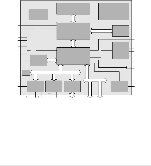
3.1 Power Supply
The power supply of the hardware module is effected via a 2x8-pin connector (Molex PS 43045-16xx, mating connector: Molex PS 43025-16xx). The pins for 12 volt have the sole purpose of supplying one or both fans with the necessary current. Thus, when no fan is installed, these pins have no function. COM3 RXD and TXD can also be used for connecting a second power supply unit, e. g. for UPS. As an ordering option SMBus signals SCL/SDA can be provided (replacing COM3 TXD/RXD).
Description |
Name |
|
Pin |
Name |
Description |
|
COM3 transmit data |
TXD |
1 |
|
9 |
RXD |
COM3 receive data |
PSU on |
PS-ON |
2 |
|
10 |
RESET# |
PSU reset |
powerbutton PSU |
PWRBTN# |
3 |
|
11 |
SVCC |
standby-supply 5V |
12 volt supply |
12V |
4 |
|
12 |
12V |
12 volt supply |
ground |
GND |
5 |
|
13 |
GND |
ground |
ground |
GND |
6 |
|
14 |
GND |
ground |
5 volt supply |
VCC |
7 |
|
15 |
VCC |
5 volt supply |
5 volt supply |
VCC |
8 |
|
16 |
VCC |
5 volt supply |
Beckhoff New Automation Technology CB2051 |
page 13 |
Chapter: Connectors |
CMOS battery |
|
|
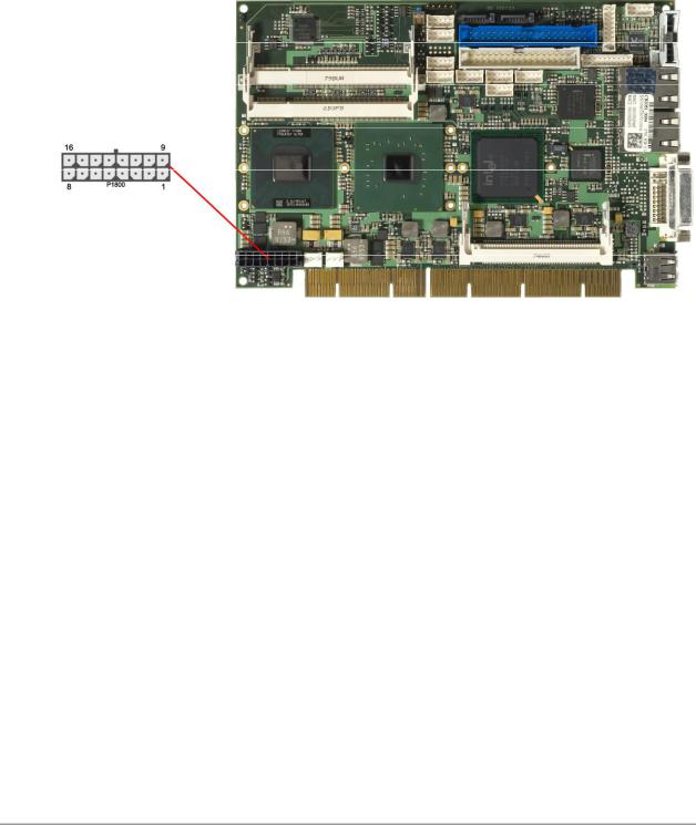
3.2 CMOS battery
The board ships with a CR2032 battery holder (Renata VBH2032-1) and 3V battery. Alternatively, an external battery can be connected via a 2pin connector (JST B2B-EH-A, mating connector: EHR-2).
Pin |
Name |
Description |
1 |
BATT |
battery 3.3 volt |
2 |
GND |
ground |
page 14 |
Beckhoff New Automation Technology CB2051 |
System |
Chapter: Connectors |
|
|
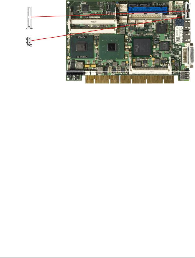
3.3 System
Some typical signals for system control are provided through a 2x9 pin connector (JST B18B-PHDSS, mating connector: PHDR-18VS). This connector combines signals for power button, reset, keyboard, speaker, and several LEDs such as harddisk LED, touch screen LED, suspend LED, and three additional LEDs which are driven by GPIOs. Of these three GPIO-LEDs, LED1 and LED2 are already provided with a series resistor. As can be seen from the pinout table below, corresponding signals are often placed vis- à-vis or at least near to each other.
Description |
Name |
|
Pin |
Name |
Description |
|
ground |
GND |
1 |
|
10 |
PWRBTN# |
on/suspend button |
ground |
GND |
2 |
|
11 |
RESET# |
reset to ground |
LED touch screen |
TOUCHLED |
3 |
|
12 |
3.3V |
3.3 volt supply |
LED suspend / ACPI |
S-LED |
4 |
|
13 |
S3.3V |
standby supply 3.3 volt |
LED harddisk |
HDLED |
5 |
|
14 |
3.3V |
3.3 volt supply |
LED GPIO device |
LED1 |
6 |
|
15 |
3.3V |
3.3 volt supply |
LED GPIO device |
LED2 |
7 |
|
16 |
LED3 |
LED GPIO device |
speaker to 5 volt |
SPEAKER |
8 |
|
17 |
KDAT |
keyboard data |
standby supply 5 volt |
(S)VCC |
9 |
|
18 |
KCLK |
keyboard clock |
Beckhoff New Automation Technology CB2051 |
page 15 |
Chapter: Connectors |
PISA Slot |
|
|
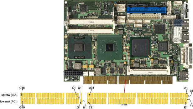
3.4 PISA Slot
The CB2051 module requires a backplane board in which it is inserted using the PISA slot. This slot combines PCI and ISA signals in one single connector which is useful in situations where limited space is an issue. The CB2051 currently supports only PCI.
 NOTE
NOTE
Please note the unusual pin numbering scheme of the PISA slot. There is an "up row" (for ISA signals) and a "low row" (for PCI signals). The former is divided into segments A through D while the latter is divided into segments E through H (cf. the illustration above).
Pinout "up row":
Description |
Name |
|
Pin |
Name |
Description |
|
IO channel check |
IOCHK# |
A1 |
|
B1 |
GND |
ground |
system data 7 |
SD7 |
A2 |
|
B2 |
RSTDRV |
reset drive |
system data 6 |
SD6 |
A3 |
|
B3 |
VCC |
5 volt supply |
system data 5 |
SD5 |
A4 |
|
B4 |
IRQ9 |
interrupt request 9 |
system data 4 |
SD4 |
A5 |
|
B5 |
-5V |
-5 volt |
system data 3 |
SD3 |
A6 |
|
B6 |
DRQ2 |
DMA request 2 |
system data 2 |
SD2 |
A7 |
|
B7 |
-12V |
-12 volt supply |
system data 1 |
SD1 |
A8 |
|
B8 |
WS0# |
wait state 0 |
system data 0 |
SD0 |
A9 |
|
B9 |
12V |
12 volt supply |
IO channel ready |
IOCHRDY |
A10 |
|
B10 |
GND |
ground |
address enable |
AEN |
A11 |
|
B11 |
SMEMW# |
memory write below 1MB |
system address 19 |
SA19 |
A12 |
|
B12 |
SMEMR# |
memory read below 1MB |
system address 18 |
SA18 |
A13 |
|
B13 |
IOW# |
IO write |
system address 17 |
SA17 |
A14 |
|
B14 |
IOR# |
IO read |
system address 16 |
SA16 |
A15 |
|
B15 |
DACK3# |
DMA acknowledge 3 |
system address 15 |
SA15 |
A16 |
|
B16 |
DRQ3 |
DMA request 3 |
system address 14 |
SA14 |
A17 |
|
B17 |
DACK1# |
DMA acknowledge 1 |
|
|
|
|
|
|
|
page 16 |
Beckhoff New Automation Technology CB2051 |
PISA Slot |
|
|
|
|
|
Chapter: Connectors |
|
|
|
|
|
|
|
|
|
|
|
|
|
|
Description |
Name |
|
Pin |
Name |
Description |
|
system address 13 |
SA13 |
A18 |
|
B18 |
DRQ1 |
DMA request 1 |
system address 12 |
SA12 |
A19 |
|
B19 |
REFRESH# |
refresh |
system address 11 |
SA11 |
A20 |
|
B20 |
SYSCLK |
system clock |
system address 10 |
SA10 |
A21 |
|
B21 |
IRQ7 |
interrupt request 7 |
system address 9 |
SA9 |
A22 |
|
B22 |
IRQ6 |
interrupt request 6 |
system address 8 |
SA8 |
A23 |
|
B23 |
IRQ5 |
interrupt request 5 |
system address 7 |
SA7 |
A24 |
|
B24 |
IRQ4 |
interrupt request 4 |
system address 6 |
SA6 |
A25 |
|
B25 |
IRQ3 |
interrupt request 3 |
system address 5 |
SA5 |
A26 |
|
B26 |
DACK2# |
DMA acknowledge 2 |
system address 4 |
SA4 |
A27 |
|
B27 |
T/C |
terminal count |
system address 3 |
SA3 |
A28 |
|
B28 |
BALE |
address latch enable |
system address 2 |
SA2 |
A29 |
|
B29 |
VCC |
5 volt supply |
system address 1 |
SA1 |
A30 |
|
B30 |
OSC14 |
14.31818 MHz |
system address 0 |
SA0 |
A31 |
|
B31 |
GND |
ground |
byte high enable |
SBHE# |
C1 |
|
D1 |
MEMCS16# |
memory chip select |
latched address 23 |
LA23 |
C2 |
|
D2 |
IOCS16# |
IO chip select |
latched address 22 |
LA22 |
C3 |
|
D3 |
IRQ10 |
interrupt request 10 |
latched address 21 |
LA21 |
C4 |
|
D4 |
IRQ11 |
interrupt request 11 |
latched address 20 |
LA20 |
C5 |
|
D5 |
IRQ12 |
interrupt request 12 |
latched address 19 |
LA19 |
C6 |
|
D6 |
IRQ13 |
interrupt request 13 |
latched address 18 |
LA18 |
C7 |
|
D7 |
IRQ14 |
interrupt request 14 |
latched address 17 |
LA17 |
C8 |
|
D8 |
DACK0# |
DMA acknowledge 0 |
memory read |
MEMR# |
C9 |
|
D9 |
DRQ0 |
DMA request 0 |
memory write |
MEMW# |
C10 |
|
D10 |
DACK5# |
DMA acknowledge 5 |
system data 8 |
SD8 |
C11 |
|
D11 |
DRQ5 |
DMA request 5 |
system data 9 |
SD9 |
C12 |
|
D12 |
DACK6# |
DMA acknowledge 6 |
system data 10 |
SD10 |
C13 |
|
D13 |
DRQ6 |
DMA request 6 |
system data 11 |
SD11 |
C14 |
|
D14 |
DACK7# |
DMA acknowledge 7 |
system data 12 |
SD12 |
C15 |
|
D15 |
DRQ7 |
DMA request 7 |
system data 13 |
SD13 |
C16 |
|
D16 |
VCC |
5 volt supply |
system data 14 |
SD14 |
C17 |
|
D17 |
MASTER# |
bus master |
system data 15 |
SD15 |
C18 |
|
D18 |
GND |
ground |
Pinout "low row": |
|
|
|
|
|
|
|
|
|
|
|
|
|
Description |
Name |
|
Pin |
Name |
Description |
|
I2C clock |
I2CLK |
E1 |
|
F1 |
I2DAT |
I2C data |
ground |
GND |
E2 |
|
F2 |
GND |
ground |
interrupt B |
INTB# |
E3 |
|
F3 |
INTA# |
interrupt A |
interrupt D |
INTD# |
E4 |
|
F4 |
INTC# |
interrupt C |
5 volt supply |
VCC |
E5 |
|
F5 |
VCC |
5 volt supply |
coded |
N/C |
E6 |
|
F6 |
N/C |
coded |
5 volt supply |
VCC |
E7 |
|
F7 |
VIO |
IO supply |
PCI reset 2 |
PRST2# |
E8 |
|
F8 |
PCLK2 |
PCI clock |
grant 0 |
GNT0# |
E9 |
|
F9 |
GND |
ground |
request 0 |
REQ0# |
E10 |
|
F10 |
GNT1# |
grant 1 |
ground |
GND |
E11 |
|
F11 |
GND |
ground |
PCI clock 1 |
PCLK1 |
E12 |
|
F12 |
REQ1# |
request 1 |
ground |
GND |
E13 |
|
F13 |
AD31 |
address/data 31 |
address/data 30 |
AD30 |
E14 |
|
F14 |
AD29 |
address/data 29 |
request 2 |
REQ2# |
E15 |
|
F15 |
PCLK3 |
PCI clock 3 |
coded |
N/C |
E16 |
|
F16 |
N/C |
coded |
grant 2 |
GNT2# |
E17 |
|
F17 |
PCLK4 |
PCI clock 4 |
address/data 28 |
AD28 |
E18 |
|
F18 |
AD27 |
address/data 27 |
address/data 26 |
AD26 |
E19 |
|
F19 |
AD25 |
address/data 25 |
|
|
|
|
|
|
|
Beckhoff New Automation Technology CB2051 |
page 17 |

Chapter: Connectors |
|
|
|
|
|
PISA Slot |
|
|
|
|
|
|
|
|
|
|
|
|
|
|
Description |
Name |
|
Pin |
Name |
Description |
|
address/data 24 |
AD24 |
E20 |
|
F20 |
CBE3# |
bus cmd/byte enable 3 |
address/data 22 |
AD22 |
E21 |
|
F21 |
AD23 |
address/data 23 |
address/data 20 |
AD20 |
E22 |
|
F22 |
AD21 |
address/data 21 |
address/data 18 |
AD18 |
E23 |
|
F23 |
AD19 |
address/data 19 |
reset |
RESET# |
E24 |
|
F24 |
REQ3# |
request 3 |
coded |
N/C |
E25 |
|
F25 |
N/C |
coded |
ground |
GND |
E26 |
|
F26 |
GNT3# |
grant 3 |
address/data 16 |
AD16 |
E27 |
|
F27 |
AD17 |
address/data 17 |
cycle frame |
FRAME# |
E28 |
|
F28 |
IRDY# |
initiator ready |
bus cmd/byte enable 2 |
CBE2# |
E29 |
|
F29 |
DEVSEL# |
device select |
target ready |
TRDY# |
E30 |
|
F30 |
PLOCK# |
lock bus |
stop req by target |
STOP# |
E31 |
|
F31 |
PERR# |
parity error |
ground |
GND |
G1 |
|
H1 |
SERR# |
system error |
reserved |
N/C |
G2 |
|
H2 |
AD15 |
address/data 15 |
bus cmd/byte enable 1 |
CBE1# |
G3 |
|
H3 |
AD14 |
address/data 14 |
parity |
PAR |
G4 |
|
H4 |
AD12 |
address/data 12 |
ground |
GND |
G5 |
|
H5 |
GND |
ground |
coded |
N/C |
G6 |
|
H6 |
N/C |
coded |
ground |
GND |
G7 |
|
H7 |
GND |
ground |
address/data 13 |
AD13 |
G8 |
|
H8 |
AD10 |
address/data 10 |
address/data 11 |
AD11 |
G9 |
|
H9 |
AD8 |
address/data 8 |
address/data 9 |
AD9 |
G10 |
|
H10 |
AD7 |
address/data 7 |
bus cmd/byte enable 0 |
CBE0# |
G11 |
|
H11 |
AD5 |
address/data 5 |
address/data 6 |
AD6 |
G12 |
|
H12 |
AD3 |
address/data 3 |
address/data 4 |
AD4 |
G13 |
|
H13 |
AD1 |
address/data 1 |
address/data 2 |
AD2 |
G14 |
|
H14 |
AD0 |
address/data 0 |
coded |
N/C |
G15 |
|
H15 |
N/C |
coded |
5 volt supply |
VCC |
G16 |
|
H16 |
VIO |
IO supply |
5 volt supply |
VCC |
G17 |
|
H17 |
VCC |
5 volt supply |
ground |
GND |
G18 |
|
H18 |
GND |
ground |
ground |
GND |
G19 |
|
H19 |
GND |
ground |
page 18 |
Beckhoff New Automation Technology CB2051 |
Mini-PCI |
Chapter: Connectors |
|
|
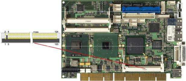
3.5 Mini-PCI
The CB2051 allows you to add expansion cards complying to the Mini-PCI standard (type III). One such card can be inserted into the Mini-PCI slot available on the board.
Description |
Name |
|
Pin |
Name |
Description |
|
reserved |
N/C |
1 |
|
2 |
N/C |
reserved |
reserved |
N/C |
3 |
|
4 |
N/C |
reserved |
reserved |
N/C |
5 |
|
6 |
N/C |
reserved |
reserved |
N/C |
7 |
|
8 |
N/C |
reserved |
reserved |
N/C |
9 |
|
10 |
N/C |
reserved |
reserved |
N/C |
11 |
|
12 |
N/C |
reserved |
reserved |
N/C |
13 |
|
14 |
N/C |
reserved |
reserved |
N/C |
15 |
|
16 |
N/C |
reserved |
interrupt B |
INTB# |
17 |
|
18 |
VCC |
5 volt supply |
3.3 volt supply |
3.3V |
19 |
|
20 |
INTA# |
interrupt A |
reserved |
N/C |
21 |
|
22 |
N/C |
reserved |
ground |
GND |
23 |
|
24 |
S3.3V |
3.3 volt supply |
PCI clock |
PCLK |
25 |
|
26 |
PRST# |
reset |
ground |
GND |
27 |
|
28 |
3.3V |
3.3 volt supply |
PCI request |
REQ# |
29 |
|
30 |
GNT# |
PCI grant |
3.3 volt supply |
3.3V |
31 |
|
32 |
GND |
ground |
address/data 31 |
AD31 |
33 |
|
34 |
PME# |
power management event |
address/data 29 |
AD29 |
35 |
|
36 |
N/C |
reserved |
ground |
GND |
37 |
|
38 |
AD30 |
address/data 30 |
address/data 27 |
AD27 |
39 |
|
40 |
3.3V |
3.3 volt supply |
address/data 25 |
AD25 |
41 |
|
42 |
AD28 |
address/data 28 |
reserved |
N/C |
43 |
|
44 |
AD26 |
address/data 26 |
bus cmd/byte enables 3 |
CBE3# |
45 |
|
46 |
AD24 |
address/data 24 |
address/data 23 |
AD23 |
47 |
|
48 |
IDSEL |
init device select |
ground |
GND |
49 |
|
50 |
GND |
ground |
address/data 21 |
AD21 |
51 |
|
52 |
AD22 |
address/data 22 |
address/data 19 |
AD19 |
53 |
|
54 |
AD20 |
address/data 20 |
ground |
GND |
55 |
|
56 |
PAR |
parity |
address/data 17 |
AD17 |
57 |
|
58 |
AD18 |
address/data 18 |
|
|
|
|
|
|
|
Beckhoff New Automation Technology CB2051 |
page 19 |

Chapter: Connectors |
|
|
|
|
|
Mini-PCI |
|
|
|
|
|
|
|
|
|
|
|
|
|
|
Description |
Name |
|
Pin |
Name |
Description |
|
bus cmd/byte enables 2 |
CBE2# |
59 |
|
60 |
AD16 |
address/data 16 |
initiator ready |
IRDY# |
61 |
|
62 |
GND |
ground |
3.3 volt supply |
3.3V |
63 |
|
64 |
FRAME# |
cycle frame |
clock running |
CLKRUN# |
65 |
|
66 |
TRDY# |
target ready |
system error |
SERR# |
67 |
|
68 |
STOP# |
stop request by target |
ground |
GND |
69 |
|
70 |
3.3V |
3.3 volt supply |
parity error |
PERR# |
71 |
|
72 |
DEVSEL# |
device select |
bus cmd/byte enables 1 |
CBE1# |
73 |
|
74 |
GND |
ground |
address/data 14 |
AD14 |
75 |
|
76 |
AD15 |
address/data 15 |
ground |
GND |
77 |
|
78 |
AD13 |
address/data 13 |
address/data 12 |
AD12 |
79 |
|
80 |
AD11 |
address/data 11 |
address/data 10 |
AD10 |
81 |
|
82 |
GND |
ground |
ground |
GND |
83 |
|
84 |
AD9 |
address/data 9 |
address/data 8 |
AD8 |
85 |
|
86 |
CBE0# |
bus cmd/byte enables 0 |
address/data 7 |
AD7 |
87 |
|
88 |
3.3V |
3.3 volt supply |
3.3 volt supply |
3.3V |
89 |
|
90 |
AD6 |
address/data 6 |
address/data 5 |
AD5 |
91 |
|
92 |
AD4 |
address/data 4 |
reserved |
N/C |
93 |
|
94 |
AD2 |
address/data 2 |
address/data 3 |
AD3 |
95 |
|
96 |
AD0 |
address/data 0 |
5 volt supply |
VCC |
97 |
|
98 |
N/C |
reserved |
address/data 1 |
AD1 |
99 |
|
100 |
N/C |
reserved |
ground |
GND |
101 |
|
102 |
GND |
ground |
reserved |
N/C |
103 |
|
104 |
GND |
ground |
reserved |
N/C |
105 |
|
106 |
N/C |
reserved |
reserved |
N/C |
107 |
|
108 |
N/C |
reserved |
reserved |
N/C |
109 |
|
110 |
N/C |
reserved |
reserved |
N/C |
111 |
|
112 |
N/C |
reserved |
reserved |
N/C |
113 |
|
114 |
GND |
ground |
reserved |
N/C |
115 |
|
116 |
N/C |
reserved |
reserved |
N/C |
117 |
|
118 |
N/C |
reserved |
reserved |
N/C |
119 |
|
120 |
N/C |
reserved |
reserved |
N/C |
121 |
|
122 |
N/C |
reserved |
5 volt supply |
VCC |
123 |
|
124 |
S3.3V |
3.3 volt supply |
page 20 |
Beckhoff New Automation Technology CB2051 |
Memory |
Chapter: Connectors |
|
|
3.6 Memory
Conventional SO-DIMM200 memory modules, as familiar from notebook computers, are used to equip the board with memory. For mechanical reasons it is possible that particular memory modules cannot be employed. Please ask your distributor for recommended memory modules.
With currently available SO-DIMM200 modules a memory extension up to 2 GByte is possible (DDR2667).
All timing parameters for different memory modules are automatically set by BIOS.
Description |
Name |
|
Pin |
Name |
Description |
|
memory reference current |
REF |
1 |
|
2 |
GND |
ground |
ground |
GND |
3 |
|
4 |
DQ4 |
data 4 |
data 0 |
DQ0 |
5 |
|
6 |
DQ5 |
data 5 |
data 1 |
DQ1 |
7 |
|
8 |
GND |
ground |
ground |
GND |
9 |
|
10 |
DQM0 |
data mask 0 |
data strobe 0 - |
DQS0# |
11 |
|
12 |
GND |
ground |
data strobe 0 + |
DQS0 |
13 |
|
14 |
DQ6 |
data 6 |
ground |
GND |
15 |
|
16 |
DQ7 |
data 7 |
data 2 |
DQ2 |
17 |
|
18 |
GND |
ground |
data 3 |
DQ3 |
19 |
|
20 |
DQ12 |
data 12 |
ground |
GND |
21 |
|
22 |
DQ13 |
data 13 |
data 8 |
DQ8 |
23 |
|
24 |
GND |
ground |
data 9 |
DQ9 |
25 |
|
26 |
DQM1 |
data mask 1 |
ground |
GND |
27 |
|
28 |
GND |
ground |
data strobe 1 - |
DQS1# |
29 |
|
30 |
CK0 |
clock 0 + |
data strobe 1 + |
DQS1 |
31 |
|
32 |
CK0# |
clock 0 - |
ground |
GND |
33 |
|
34 |
GND |
ground |
data 10 |
DQ10 |
35 |
|
36 |
DQ14 |
data 14 |
data 11 |
DQ11 |
37 |
|
38 |
DQ15 |
data 15 |
ground |
GND |
39 |
|
40 |
GND |
ground |
Beckhoff New Automation Technology CB2051 |
page 21 |

Chapter: Connectors |
|
|
|
|
|
Memory |
|
|
|
|
|
|
|
|
|
|
|
|
|
|
Description |
Name |
|
Pin |
Name |
Description |
|
ground |
GND |
41 |
|
42 |
GND |
ground |
data 16 |
DQ16 |
43 |
|
44 |
DQ20 |
data 20 |
data 17 |
DQ17 |
45 |
|
46 |
DQ21 |
data 21 |
ground |
GND |
47 |
|
48 |
GND |
ground |
data strobe 2 - |
DQS2# |
49 |
|
50 |
N/C |
reserved |
data strobe 2 + |
DQS2 |
51 |
|
52 |
DQM2 |
data mask 2 |
ground |
GND |
53 |
|
54 |
GND |
ground |
data 18 |
DQ18 |
55 |
|
56 |
DQ22 |
data 22 |
data 19 |
DQ19 |
57 |
|
58 |
DQ23 |
data 23 |
ground |
GND |
59 |
|
60 |
GND |
ground |
data 24 |
DQ24 |
61 |
|
62 |
DQ28 |
data 28 |
data 25 |
DQ25 |
63 |
|
64 |
DQ29 |
data 29 |
ground |
GND |
65 |
|
66 |
GND |
ground |
data mask 3 |
DQM3 |
67 |
|
68 |
DQS3# |
data strobe 3 - |
reserved |
N/C |
69 |
|
70 |
DQS3 |
data strobe 3 + |
ground |
GND |
71 |
|
72 |
GND |
ground |
data 26 |
DQ26 |
73 |
|
74 |
DQ30 |
data 30 |
data 27 |
DQ27 |
75 |
|
76 |
DQ31 |
data 31 |
ground |
GND |
77 |
|
78 |
GND |
ground |
clock enables 0 |
CKE0 |
79 |
|
80 |
CKE1 |
clock enables 1 |
1.8 volt supply |
1.8V |
81 |
|
82 |
1.8V |
1.8 volt supply |
reserved |
N/C |
83 |
|
84 |
N/C |
reserved |
SDRAM bank 2 |
BA2 |
85 |
|
86 |
N/C |
reserved |
1.8 volt supply |
1.8V |
87 |
|
88 |
1.8V |
1.8 volt supply |
address 12 |
A12 |
89 |
|
90 |
A11 |
address 11 |
address 9 |
A9 |
91 |
|
92 |
A7 |
address 7 |
address 8 |
A8 |
93 |
|
94 |
A6 |
address 6 |
1.8 volt supply |
1.8V |
95 |
|
96 |
1.8V |
1.8 volt supply |
address 5 |
A5 |
97 |
|
98 |
A4 |
address 4 |
address 3 |
A3 |
99 |
|
100 |
A12 |
address 2 |
address 1 |
A1 |
101 |
|
102 |
A0 |
address 0 |
1.8 volt supply |
1.8V |
103 |
|
104 |
1.8V |
1.8 volt supply |
address 10 |
A10 |
105 |
|
106 |
BA1 |
SDRAM bank 1 |
SDRAM bank 0 |
BA0 |
107 |
|
108 |
RAS# |
row address strobe |
write enable |
WE# |
109 |
|
110 |
S0# |
chip select 0 |
1.8 volt supply |
1.8V |
111 |
|
112 |
1.8V |
1.8 volt supply |
column address strobe |
CAS# |
113 |
|
114 |
ODT0 |
on die termination 0 |
chip select 1 |
S1# |
115 |
|
116 |
A13 |
address 13 |
1.8 volt supply |
1.8V |
117 |
|
118 |
1.8V |
1.8 volt supply |
on die termination 1 |
ODT1 |
119 |
|
120 |
N/C |
reserved |
ground |
GND |
121 |
|
122 |
GND |
ground |
data 32 |
DQ32 |
123 |
|
124 |
DQ36 |
data 36 |
data 33 |
DQ33 |
125 |
|
126 |
DQ37 |
data 37 |
ground |
GND |
127 |
|
128 |
GND |
ground |
data strobe 4 - |
DQS4# |
129 |
|
130 |
DQM4 |
data mask 4 |
data strobe 4 + |
DQS4 |
131 |
|
132 |
GND |
ground |
ground |
GND |
133 |
|
134 |
DQ38 |
data 38 |
data 34 |
DQ34 |
135 |
|
136 |
DQ39 |
data 39 |
data 35 |
DQ35 |
137 |
|
138 |
GND |
ground |
ground |
GND |
139 |
|
140 |
DQ44 |
data 44 |
data 40 |
DQ40 |
141 |
|
142 |
DQ45 |
data 45 |
data 41 |
DQ41 |
143 |
|
144 |
GND |
ground |
ground |
GND |
145 |
|
146 |
DQS5# |
data strobe 5 - |
data mask 5 |
DQM5 |
147 |
|
148 |
DQS5 |
data strobe 5 + |
ground |
GND |
149 |
|
150 |
GND |
ground |
page 22 |
Beckhoff New Automation Technology CB2051 |

Memory |
|
|
|
|
|
Chapter: Connectors |
|
|
|
|
|
|
|
|
|
|
|
|
|
|
Description |
Name |
|
Pin |
Name |
Description |
|
data 42 |
DQ42 |
151 |
|
152 |
DQ46 |
data 46 |
data 43 |
DQ43 |
153 |
|
154 |
DQ47 |
data 47 |
ground |
GND |
155 |
|
156 |
GND |
ground |
data 48 |
DQ48 |
157 |
|
158 |
DQ52 |
data 52 |
data 49 |
DQ49 |
159 |
|
160 |
DQ53 |
data 53 |
ground |
GND |
161 |
|
162 |
GND |
ground |
test |
TEST |
163 |
|
164 |
CK1 |
clock 1 + |
ground |
GND |
165 |
|
166 |
CK1# |
clock 1 - |
data strobe 6 - |
DQS6# |
167 |
|
168 |
GND |
ground |
data strobe 6 |
DQS6 |
169 |
|
170 |
DQM6 |
data mask 6 |
ground |
GND |
171 |
|
172 |
GND |
ground |
data 50 |
DQ50 |
173 |
|
174 |
DQ54 |
data 54 |
data 51 |
DQ51 |
175 |
|
176 |
DQ55 |
data 55 |
ground |
GND |
177 |
|
178 |
GND |
ground |
data 56 |
DQ56 |
179 |
|
180 |
DQ60 |
data 60 |
data 57 |
DQ57 |
181 |
|
182 |
DQ61 |
data 61 |
ground |
GND |
183 |
|
184 |
GND |
ground |
data mask 7 |
DQM7 |
185 |
|
186 |
DQS7# |
data strobe 7 - |
ground |
GND |
187 |
|
188 |
DQS7 |
data strobe 7 + |
data 58 |
DQ58 |
189 |
|
190 |
GND |
ground |
data 59 |
DQ59 |
191 |
|
192 |
DQ62 |
data 62 |
ground |
GND |
193 |
|
194 |
DQ63 |
data 63 |
SMBus data |
SDA |
195 |
|
196 |
GND |
ground |
SMBus clock |
SCL |
197 |
|
198 |
SA0 |
SPD address |
3.3 volt supply |
3.3V |
199 |
|
200 |
SA1 |
SPD address |
Beckhoff New Automation Technology CB2051 |
page 23 |
Chapter: Connectors |
SATA Interfaces |
|
|
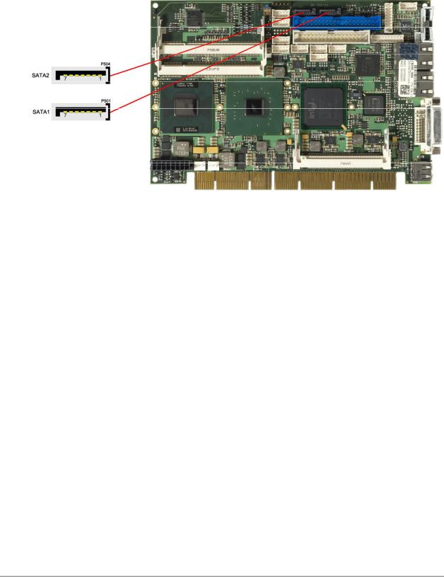
3.7 SATA Interfaces
The CB2051 provides two SATA interfaces allowing transfer rates of up to 3 GBit per second. These interfaces are made available via two 7 pin connectors.
The required settings are made in the BIOS setup.
Pinbelegung SATA:
Pin |
Name |
Beschreibung |
1 |
GND |
Masse |
2 |
SATATX |
SATA Senden + |
3 |
SATATX# |
SATA Senden - |
4 |
GND |
Masse |
5 |
SATARX |
SATA Empfangen + |
6 |
SATARX# |
SATA Empfangen - |
7 |
GND |
Masse |
page 24 |
Beckhoff New Automation Technology CB2051 |
 Loading...