


 Loading...
Documentation | EN
EL6090
Display Terminal
2021-03-11 | Version: 2.6

|
|
|
|
Table of contents |
Table of contents |
|
|||
1 |
Foreword .................................................................................................................................................... |
|
5 |
|
|
1.1 |
Notes on the documentation.............................................................................................................. |
5 |
|
|
1.2 |
Safety instructions ............................................................................................................................. |
6 |
|
|
1.3 |
Documentation issue status .............................................................................................................. |
7 |
|
|
1.4 |
Version identification of EtherCAT devices ....................................................................................... |
8 |
|
|
|
1.4.1 |
Beckhoff Identification Code (BIC)................................................................................... |
12 |
2 |
Product overview..................................................................................................................................... |
14 |
||
|
2.1 |
Introduction...................................................................................................................................... |
14 |
|
|
2.2 |
Technical data ................................................................................................................................. |
15 |
|
3 |
Basics communication ........................................................................................................................... |
16 |
||
|
3.1 |
EtherCAT basics.............................................................................................................................. |
16 |
|
|
3.2 |
EtherCAT cabling – wire-bound....................................................................................................... |
16 |
|
|
3.3 |
General notes for setting the watchdog........................................................................................... |
17 |
|
|
3.4 |
EtherCAT State Machine................................................................................................................. |
19 |
|
|
3.5 |
CoE Interface................................................................................................................................... |
20 |
|
|
3.6 |
Distributed Clock ............................................................................................................................. |
25 |
|
4 |
Mounting and wiring................................................................................................................................ |
26 |
||
|
4.1 |
Instructions for ESD protection........................................................................................................ |
26 |
|
|
4.2 |
Recommended mounting rails......................................................................................................... |
26 |
|
|
4.3 |
Mounting and demounting - terminals with front unlocking ............................................................. |
26 |
|
|
4.4 |
Installation positions ........................................................................................................................ |
28 |
|
|
4.5 |
Positioning of passive Terminals ..................................................................................................... |
30 |
|
5 |
Commissioning........................................................................................................................................ |
32 |
||
|
5.1 |
TwinCAT Quick Start ....................................................................................................................... |
32 |
|
|
|
5.1.1 |
TwinCAT 2 ....................................................................................................................... |
35 |
|
|
5.1.2 |
TwinCAT 3 ....................................................................................................................... |
45 |
|
5.2 |
TwinCAT Development Environment .............................................................................................. |
58 |
|
|
|
5.2.1 |
Installation of the TwinCAT real-time driver..................................................................... |
59 |
|
|
5.2.2 |
Notes regarding ESI device description........................................................................... |
64 |
|
|
5.2.3 |
OFFLINE configuration creation ...................................................................................... |
68 |
|
|
5.2.4 |
ONLINE configuration creation ........................................................................................ |
73 |
|
|
5.2.5 |
EtherCAT subscriber configuration.................................................................................. |
81 |
|
5.3 |
General Notes - EtherCAT Slave Application.................................................................................. |
90 |
|
|
5.4 |
Object description and parameterization ......................................................................................... |
98 |
|
|
|
5.4.1 |
Restore object.................................................................................................................. |
98 |
|
|
5.4.2 |
Objects for the display ..................................................................................................... |
98 |
|
|
5.4.3 |
Objects for the NAVI switch ............................................................................................. |
99 |
|
|
5.4.4 |
Objects for the counters and time measurement............................................................. |
99 |
|
|
5.4.5 |
Objects for the display of process data in the display via placeholders........................... |
99 |
|
|
5.4.6 |
Objects for activating and resetting the counters and time values ................................ |
100 |
|
|
5.4.7 |
Objects for the operating hours counter ........................................................................ |
100 |
|
|
5.4.8 |
Command object............................................................................................................ |
100 |
|
|
5.4.9 |
Standard objects............................................................................................................ |
100 |
|
|
|
|
|
EL6090 |
|
Version: 2.6 |
3 |
|

Table of contents
|
5.4.10 |
Profile - specific objects ................................................................................................... |
104 |
5.5 |
Basic function principles ................................................................................................................ |
106 |
|
5.6 |
Display |
........................................................................................................................................... |
108 |
5.7 |
Counters ..................................................................................................and time measurement |
111 |
|
5.8 |
Application .....................................................................................................................examples |
113 |
|
|
5.8.1 ........................................................................ |
EL6090 - Example for using the display |
113 |
|
5.8.2 .......................................................... |
EL6090 - Example for using counters and timers |
114 |
6 Appendix ................................................................................................................................................ |
|
117 |
|
6.1 |
EtherCAT ...........................................................................................................AL Status Codes |
117 |
|
6.2 |
UL notice ....................................................................................................................................... |
117 |
|
6.3 |
Firmware ...................................................................................................................compatibility |
118 |
|
6.4 |
Firmware ....................................................................................Update EL/ES/EM/ELM/EPxxxx |
118 |
|
|
6.4.1 ..................................................................................... |
Device description ESI file/XML |
119 |
|
6.4.2 .................................................................................................... |
Firmware explanation |
122 |
|
6.4.3 ................................................................................. |
Updating controller firmware * .efw |
123 |
|
6.4.4 ....................................................................................................... |
FPGA firmware * .rbf |
125 |
|
6.4.5 .................................................... |
Simultaneous updating of several EtherCAT devices |
129 |
6.5 |
Restoring ...........................................................................................................the delivery state |
130 |
|
6.6 |
Support ......................................................................................................................and Service |
131 |
|
4 |
Version: 2.6 |
EL6090 |

Foreword
1 Foreword
1.1Notes on the documentation
Intended audience
This description is only intended for the use of trained specialists in control and automation engineering who are familiar with the applicable national standards.
It is essential that the documentation and the following notes and explanations are followed when installing and commissioning these components.
It is the duty of the technical personnel to use the documentation published at the respective time of each installation and commissioning.
The responsible staff must ensure that the application or use of the products described satisfy all the requirements for safety, including all the relevant laws, regulations, guidelines and standards.
Disclaimer
The documentation has been prepared with care. The products described are, however, constantly under development.
We reserve the right to revise and change the documentation at any time and without prior announcement.
No claims for the modification of products that have already been supplied may be made on the basis of the data, diagrams and descriptions in this documentation.
Trademarks
Beckhoff®, TwinCAT®, EtherCAT®, EtherCAT G®, EtherCAT G10®, EtherCAT P®, Safety over EtherCAT®, TwinSAFE®, XFC®, XTS® and XPlanar® are registered trademarks of and licensed by Beckhoff Automation GmbH. Other designations used in this publication may be trademarks whose use by third parties for their own purposes could violate the rights of the owners.
Patent Pending
The EtherCAT Technology is covered, including but not limited to the following patent applications and patents: EP1590927, EP1789857, EP1456722, EP2137893, DE102015105702 with corresponding applications or registrations in various other countries.
EtherCAT® is registered trademark and patented technology, licensed by Beckhoff Automation GmbH, Germany.
Copyright
© Beckhoff Automation GmbH & Co. KG, Germany.
The reproduction, distribution and utilization of this document as well as the communication of its contents to others without express authorization are prohibited.
Offenders will be held liable for the payment of damages. All rights reserved in the event of the grant of a patent, utility model or design.
EL6090 |
Version: 2.6 |
5 |
Foreword
1.2Safety instructions
Safety regulations
Please note the following safety instructions and explanations!
Product-specific safety instructions can be found on following pages or in the areas mounting, wiring, commissioning etc.
Exclusion of liability
All the components are supplied in particular hardware and software configurations appropriate for the application. Modifications to hardware or software configurations other than those described in the documentation are not permitted, and nullify the liability of Beckhoff Automation GmbH & Co. KG.
Personnel qualification
This description is only intended for trained specialists in control, automation and drive engineering who are familiar with the applicable national standards.
Description of instructions
In this documentation the following instructions are used.
These instructions must be read carefully and followed without fail!
 DANGER
Serious risk of injury!
Failure to follow this safety instruction directly endangers the life and health of persons.
 WARNING
Risk of injury!
Failure to follow this safety instruction endangers the life and health of persons.
 CAUTION
Personal injuries!
Failure to follow this safety instruction can lead to injuries to persons.
NOTE
Damage to environment/equipment or data loss
Failure to follow this instruction can lead to environmental damage, equipment damage or data loss.
Tip or pointer
This symbol indicates information that contributes to better understanding.
6 |
Version: 2.6 |
EL6090 |

Foreword
1.3Documentation issue status
Version |
Comment |
|
2.6 |
• |
Update chapter “Technical data” |
|
• |
Update structure |
2.5 |
• |
Update chapter “Application samples” |
|
• Update chapter “Firmware compatibility” |
|
|
• |
Update structure |
2.4 |
• |
Update chapter “UL notice” |
|
• Update chapter “Firmware compatibility” |
|
|
• |
Update structure |
2.3 |
• |
Update chapter “Counters and time measurement” |
|
• |
Update structure |
2.2 |
• |
Update chapter “Notes on the documentation” |
|
• Correction chapter “Technical data” |
|
|
• Addenda chapter “TwinCAT Quick Start“ |
|
|
• Correction link to example files |
|
2.1 |
• |
Update chapter “Object description” |
|
• |
Update chapter “Display” |
|
• |
Update revision status |
2.0 |
• |
Migration |
|
• |
Update revision status |
1.2 |
• |
Corrections |
|
• |
1. Publication |
1.1 |
• |
Corrections |
1.0 |
• |
Provisional documentation for EL6090 |
EL6090 |
Version: 2.6 |
7 |

Foreword
1.4Version identification of EtherCAT devices
Designation
A Beckhoff EtherCAT device has a 14-digit designation, made up of
• |
family key |
|
|
|
|
|
|
• |
type |
|
|
|
|
|
|
• |
version |
|
|
|
|
|
|
• |
revision |
|
|
|
|
|
|
|
|
|
|
|
|
||
Example |
Family |
Type |
|
Version |
Revision |
||
EL3314-0000-0016 |
EL terminal |
3314 |
(4-channel thermocouple |
0000 |
(basic type) |
0016 |
|
|
|
(12 mm, non- |
terminal) |
|
|
|
|
|
|
pluggable connection |
|
|
|
|
|
|
|
level) |
|
|
|
|
|
ES3602-0010-0017 |
ES terminal |
3602 |
(2-channel voltage |
0010 |
(high- |
0017 |
|
|
|
(12 mm, pluggable |
measurement) |
precision version) |
|
||
|
|
connection level) |
|
|
|
|
|
CU2008-0000-0000 |
CU device |
2008 |
(8-port fast ethernet switch) |
0000 |
(basic type) |
0000 |
|
Notes
•The elements mentioned above result in the technical designation. EL3314-0000-0016 is used in the example below.
•EL3314-0000 is the order identifier, in the case of “-0000” usually abbreviated to EL3314. “-0016” is the EtherCAT revision.
•The order identifier is made up of
-family key (EL, EP, CU, ES, KL, CX, etc.)
-type (3314)
-version (-0000)
•The revision -0016 shows the technical progress, such as the extension of features with regard to the EtherCAT communication, and is managed by Beckhoff.
In principle, a device with a higher revision can replace a device with a lower revision, unless specified otherwise, e.g. in the documentation.
Associated and synonymous with each revision there is usually a description (ESI, EtherCAT Slave Information) in the form of an XML file, which is available for download from the Beckhoff web site. From 2014/01 the revision is shown on the outside of the IP20 terminals, see Fig. “EL5021 EL terminal, standard IP20 IO device with batch number and revision ID (since 2014/01)”.
•The type, version and revision are read as decimal numbers, even if they are technically saved in hexadecimal.
Identification number
Beckhoff EtherCAT devices from the different lines have different kinds of identification numbers:
Production lot/batch number/serial number/date code/D number
The serial number for Beckhoff IO devices is usually the 8-digit number printed on the device or on a sticker. The serial number indicates the configuration in delivery state and therefore refers to a whole production batch, without distinguishing the individual modules of a batch.
Structure of the serial number: KK YY FF HH
KK - week of production (CW, calendar week)
YY - year of production
FF - firmware version
HH - hardware version
8 |
Version: 2.6 |
EL6090 |

Foreword
Example with
Ser. no.: 12063A02: 12 - production week 12 06 - production year 2006 3A - firmware version 3A 02 - hardware version 02
Exceptions can occur in the IP67 area, where the following syntax can be used (see respective device documentation):
Syntax: D ww yy x y z u
D - prefix designation ww - calendar week yy - year
x - firmware version of the bus PCB y - hardware version of the bus PCB z - firmware version of the I/O PCB u - hardware version of the I/O PCB
Example: D.22081501 calendar week 22 of the year 2008 firmware version of bus PCB: 1 hardware version of bus PCB: 5 firmware version of I/O PCB: 0 (no firmware necessary for this PCB) hardware version of I/O PCB: 1
Unique serial number/ID, ID number
In addition, in some series each individual module has its own unique serial number.
See also the further documentation in the area
•IP67: EtherCAT Box
•Safety: TwinSafe
•Terminals with factory calibration certificate and other measuring terminals
Examples of markings
Fig. 1: EL5021 EL terminal, standard IP20 IO device with serial/ batch number and revision ID (since 2014/01)
EL6090 |
Version: 2.6 |
9 |
Foreword
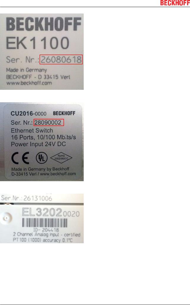
Fig. 2: EK1100 EtherCAT coupler, standard IP20 IO device with serial/ batch number
Fig. 3: CU2016 switch with serial/ batch number
Fig. 4: EL3202-0020 with serial/ batch number 26131006 and unique ID-number 204418
10 |
Version: 2.6 |
EL6090 |
Foreword
Fig. 5: EP1258-00001 IP67 EtherCAT Box with batch number/ date code 22090101 and unique serial number 158102
Fig. 6: EP1908-0002 IP67 EtherCAT Safety Box with batch number/ date code 071201FF and unique serial number 00346070
Fig. 7: EL2904 IP20 safety terminal with batch number/ date code 50110302 and unique serial number 00331701
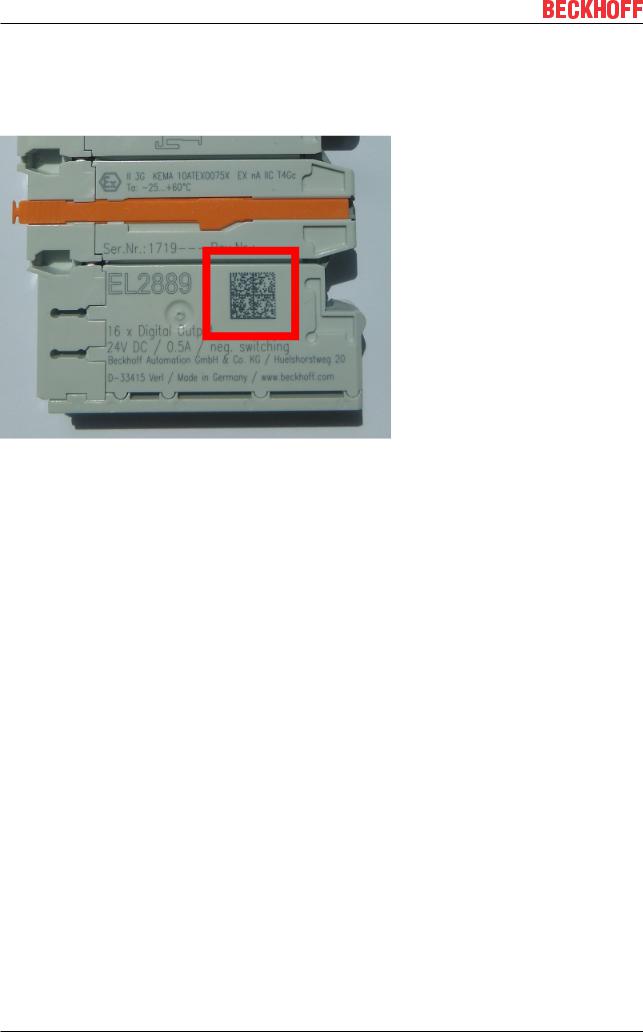
Fig. 8: ELM3604-0002 terminal with unique ID number (QR code) 100001051 and serial/ batch number 44160201
EL6090 |
Version: 2.6 |
11 |
Foreword
1.4.1Beckhoff Identification Code (BIC)
The Beckhoff Identification Code (BIC) is increasingly being applied to Beckhoff products to uniquely identify the product. The BIC is represented as a Data Matrix Code (DMC, code scheme ECC200), the content is based on the ANSI standard MH10.8.2-2016.
Fig. 9: BIC as data matrix code (DMC, code scheme ECC200)
The BIC will be introduced step by step across all product groups.
Depending on the product, it can be found in the following places:
•on the packaging unit
•directly on the product (if space suffices)
•on the packaging unit and the product
The BIC is machine-readable and contains information that can also be used by the customer for handling and product management.
Each piece of information can be uniquely identified using the so-called data identifier
(ANSI MH10.8.2-2016). The data identifier is followed by a character string. Both together have a maximum length according to the table below. If the information is shorter, spaces are added to it. The data under positions 1 to 4 are always available.
The following information is contained:
12 |
Version: 2.6 |
EL6090 |

|
|
|
|
|
Foreword |
|
|
|
|
|
|
Item |
Type of |
Explanation |
Data |
Number of digits |
Example |
no. |
information |
|
identifier |
incl. data identifier |
|
1 |
Beckhoff order |
Beckhoff order number |
1P |
8 |
1P072222 |
|
number |
|
|
|
|
2 |
Beckhoff Traceability |
Unique serial number, |
S |
12 |
SBTNk4p562d7 |
|
Number (BTN) |
see note below |
|
|
|
3 |
Article description |
Beckhoff article |
1K |
32 |
1KEL1809 |
|
|
description, e.g. |
|
|
|
|
|
EL1008 |
|
|
|
4 |
Quantity |
Quantity in packaging |
Q |
6 |
Q1 |
|
|
unit, e.g. 1, 10, etc. |
|
|
|
5 |
Batch number |
Optional: Year and week |
2P |
14 |
2P401503180016 |
|
|
of production |
|
|
|
6 |
ID/serial number |
Optional: Present-day |
51S |
12 |
51S678294104 |
|
|
serial number system, |
|
|
|
|
|
e.g. with safety products |
|
|
|
|
|
or calibrated terminals |
|
|
|
7 |
Variant number |
Optional: Product variant |
30P |
32 |
30PF971, 2*K183 |
|
|
number on the basis of |
|
|
|
|
|
standard products |
|
|
|
... |
|
|
|
|
|
Further types of information and data identifiers are used by Beckhoff and serve internal processes.
Structure of the BIC
Example of composite information from item 1 to 4 and 6. The data identifiers are marked in red for better display:
BTN
An important component of the BIC is the Beckhoff Traceability Number (BTN, item no. 2). The BTN is a unique serial number consisting of eight characters that will replace all other serial number systems at Beckhoff in the long term (e.g. batch designations on IO components, previous serial number range for safety products, etc.). The BTN will also be introduced step by step, so it may happen that the BTN is not yet coded in the BIC.
NOTE
This information has been carefully prepared. However, the procedure described is constantly being further developed. We reserve the right to revise and change procedures and documentation at any time and without prior notice. No claims for changes can be made from the information, illustrations and descriptions in this information.
EL6090 |
Version: 2.6 |
13 |

Product overview
2 Product overview
2.1Introduction
Fig. 10: EL6090
Display terminal
The display terminal has an illuminated, low-reflection LC display with two lines of 16 characters. It can be used, for example, for displaying status messages or diagnostic information. A non-resettable operating hour meter is integrated and can be displayed and also read out via the controller.
Via the user program dynamic and static application-specific texts can be displayed, e.g. “Production counter: (count value)”. If the output text is longer than 16 characters, the terminal automatically switches to scrolling text mode. Two special characters can be defined via a 5x8 pixel matrix.
The statuses of the navigation switch – up, down, left, right and Enter – are transmitted to the controller as binary variables and can be used to control the display.
4 x 32-bit timer values are available. They are activated through 4 bits in the process data. If the flag is set the time value is incremented each second. The time values can be reset.
This can be used, for example, to count the time for which a machine was in production or in an error state.
In addition, 4 32-bit counters are available. They are activated through 4 bits in the process data and are incremented in the event of a positive edge.
The data for the 4 timers, the 4 counters and the operating hours counter are saved on the terminal every 15 minutes. In addition, the data can be saved manually when the system is shut down. If this feature is not used, the maximum inaccuracy is 15 minutes.
The operating hours counter is specified with a resolution of 1 second per digit. With 32 bits this means that an overflow won't occur for 139 years. The EEPROM for storing the counter, timer and operating hours counter data can hold more than 100 years’ worth of data, based on 15-minutes write cycles.
14 |
Version: 2.6 |
EL6090 |

Product overview
Quick links
•EtherCAT basics
•EL6090 basics [} 106]
•EL6090 technical data [} 15]
•The display [} 108]
•Counters, timers and operating hours counter [} 111]
•Object description and parameterization [} 98]
•EL6090 examples [} 113]
2.2 |
|
Technical data |
|
|
Technical data |
EL6090 |
|||
Display |
|
|
LC display, 2 x 16 characters (> 16 characters = |
|
|
|
|
|
scrolling text mode), switchable lighting |
Special characters |
max. 2 characters, 5 x 8 pixels |
|||
Switch inputs |
|
|
Navigation buttons: up, down, left, right, Enter |
|
Operating hour counter |
32-bit, overflow after 136 years (not resettable) |
|||
|
|
|
|
Secure data storage > 100 years (with a 15-minute |
|
|
|
|
write interval) |
|
|
|
|
Accuracy: +/- 50 ppm |
Timing |
|
|
4 x 32-bit second counter (resettable) |
|
Counter |
|
|
4 x 32-bit counter (resettable) |
|
Saving interval |
Manual/auto every 15 minutes |
|||
Housing |
|
|
24 mm housing |
|
Supply voltage for electronic |
via the E-bus |
|||
Current consumption via E-bus |
typ. 80 mA |
|||
Configuration |
|
|
via TwinCAT System Manager |
|
Weight |
|
|
approx. 70 g |
|
Permissible ambient temperature range during |
0°C ... + 55°C |
|||
operation |
|
|
|
|
Permissible ambient temperature range during |
-25°C ... + 85°C |
|||
storage |
|
|
|
|
Permissible relative humidity |
95 %, no condensation |
|||
Dimensions (W x H x D) |
approx. 24 mm x 100 mm x 70 mm |
|||
Mounting [} 26] |
on 35 mm mounting rail conforms to EN 60715 |
|||
|
|
|
|
|
Vibration/shock resistance |
conforms to EN 60068-2-6 / EN 60068-2-27 |
|||
EMC immunity/emission |
conforms to EN 61000-6-2 / EN 61000-6-4 |
|||
Protection class |
IP20 |
|||
Installation position |
variable |
|||
Approval |
|
|
CE |
|
|
|
|
|
cULus [} 117] |
EL6090 |
Version: 2.6 |
15 |

Basics communication
3 Basics communication
3.1EtherCAT basics
Please refer to the EtherCAT System Documentation for the EtherCAT fieldbus basics.
3.2EtherCAT cabling – wire-bound
The cable length between two EtherCAT devices must not exceed 100 m. This results from the FastEthernet technology, which, above all for reasons of signal attenuation over the length of the cable, allows a maximum link length of 5 + 90 + 5 m if cables with appropriate properties are used. See also the Design recommendations for the infrastructure for EtherCAT/Ethernet.
Cables and connectors
For connecting EtherCAT devices only Ethernet connections (cables + plugs) that meet the requirements of at least category 5 (CAt5) according to EN 50173 or ISO/IEC 11801 should be used. EtherCAT uses 4 wires for signal transfer.
EtherCAT uses RJ45 plug connectors, for example. The pin assignment is compatible with the Ethernet standard (ISO/IEC 8802-3).
Pin |
Color of conductor |
Signal |
Description |
1 |
yellow |
TD + |
Transmission Data + |
2 |
orange |
TD - |
Transmission Data - |
3 |
white |
RD + |
Receiver Data + |
6 |
blue |
RD - |
Receiver Data - |
Due to automatic cable detection (auto-crossing) symmetric (1:1) or cross-over cables can be used between EtherCAT devices from Beckhoff.
Recommended cables
It is recommended to use the appropriate Beckhoff components e.g.
-cable sets ZK1090-9191-xxxx respectively
-RJ45 connector, field assembly ZS1090-0005
-EtherCAT cable, field assembly ZB9010, ZB9020
Suitable cables for the connection of EtherCAT devices can be found on the Beckhoff website!
E-Bus supply
A bus coupler can supply the EL terminals added to it with the E-bus system voltage of 5 V; a coupler is thereby loadable up to 2 A as a rule (see details in respective device documentation).
Information on how much current each EL terminal requires from the E-bus supply is available online and in the catalogue. If the added terminals require more current than the coupler can supply, then power feed terminals (e.g. EL9410) must be inserted at appropriate places in the terminal strand.
The pre-calculated theoretical maximum E-Bus current is displayed in the TwinCAT System Manager. A shortfall is marked by a negative total amount and an exclamation mark; a power feed terminal is to be placed before such a position.
16 |
Version: 2.6 |
EL6090 |

Basics communication
Fig. 11: System manager current calculation
NOTE
Malfunction possible!
The same ground potential must be used for the E-Bus supply of all EtherCAT terminals in a terminal block!
3.3General notes for setting the watchdog
ELxxxx terminals are equipped with a safety feature (watchdog) that switches off the outputs after a specifiable time e.g. in the event of an interruption of the process data traffic, depending on the device and settings, e.g. in OFF state.
The EtherCAT slave controller (ESC) in the EL2xxx terminals features two watchdogs:
•SM watchdog (default: 100 ms)
•PDI watchdog (default: 100 ms)
SM watchdog (SyncManager Watchdog)
The SyncManager watchdog is reset after each successful EtherCAT process data communication with the terminal. If no EtherCAT process data communication takes place with the terminal for longer than the set and activated SM watchdog time, e.g. in the event of a line interruption, the watchdog is triggered and the outputs are set to FALSE. The OP state of the terminal is unaffected. The watchdog is only reset after a successful EtherCAT process data access. Set the monitoring time as described below.
The SyncManager watchdog monitors correct and timely process data communication with the ESC from the EtherCAT side.
PDI watchdog (Process Data Watchdog)
If no PDI communication with the EtherCAT slave controller (ESC) takes place for longer than the set and activated PDI watchdog time, this watchdog is triggered.
PDI (Process Data Interface) is the internal interface between the ESC and local processors in the EtherCAT slave, for example. The PDI watchdog can be used to monitor this communication for failure.
The PDI watchdog monitors correct and timely process data communication with the ESC from the application side.
The settings of the SMand PDI-watchdog must be done for each slave separately in the TwinCAT System Manager.
EL6090 |
Version: 2.6 |
17 |

Basics communication
Fig. 12: EtherCAT tab -> Advanced Settings -> Behavior -> Watchdog
Notes:
•the multiplier is valid for both watchdogs.
•each watchdog has its own timer setting, the outcome of this in summary with the multiplier is a resulting time.
•Important: the multiplier/timer setting is only loaded into the slave at the start up, if the checkbox is activated.
If the checkbox is not activated, nothing is downloaded and the ESC settings remain unchanged.
Multiplier
Both watchdogs receive their pulses from the local terminal cycle, divided by the watchdog multiplier:
1/25 MHz * (watchdog multiplier + 2) = 100 µs (for default setting of 2498 for the multiplier)
The standard setting of 1000 for the SM watchdog corresponds to a release time of 100 ms.
The value in multiplier + 2 corresponds to the number of basic 40 ns ticks representing a watchdog tick. The multiplier can be modified in order to adjust the watchdog time over a larger range.
Example “Set SM watchdog”
This checkbox enables manual setting of the watchdog times. If the outputs are set and the EtherCAT communication is interrupted, the SM watchdog is triggered after the set time and the outputs are erased. This setting can be used for adapting a terminal to a slower EtherCAT master or long cycle times. The default SM watchdog setting is 100 ms. The setting range is 0...65535. Together with a multiplier with a range of 1...65535 this covers a watchdog period between 0...~170 seconds.
18 |
Version: 2.6 |
EL6090 |
Basics communication
Calculation
Multiplier = 2498 → watchdog base time = 1 / 25 MHz * (2498 + 2) = 0.0001 seconds = 100 µs SM watchdog = 10000 → 10000 * 100 µs = 1 second watchdog monitoring time
 CAUTION
Undefined state possible!
The function for switching off of the SM watchdog via SM watchdog = 0 is only implemented in terminals from version -0016. In previous versions this operating mode should not be used.
 CAUTION
Damage of devices and undefined state possible!
If the SM watchdog is activated and a value of 0 is entered the watchdog switches off completely. This is the deactivation of the watchdog! Set outputs are NOT set in a safe state, if the communication is interrupted.
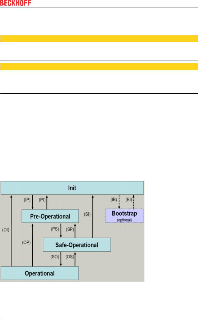
3.4EtherCAT State Machine
The state of the EtherCAT slave is controlled via the EtherCAT State Machine (ESM). Depending upon the state, different functions are accessible or executable in the EtherCAT slave. Specific commands must be sent by the EtherCAT master to the device in each state, particularly during the bootup of the slave.
A distinction is made between the following states:
•Init
•Pre-Operational
•Safe-Operational and
•Operational
•Boot
The regular state of each EtherCAT slave after bootup is the OP state.
Fig. 13: States of the EtherCAT State Machine
EL6090 |
Version: 2.6 |
19 |

Basics communication
Init
After switch-on the EtherCAT slave in the Init state. No mailbox or process data communication is possible. The EtherCAT master initializes sync manager channels 0 and 1 for mailbox communication.
Pre-Operational (Pre-Op)
During the transition between Init and Pre-Op the EtherCAT slave checks whether the mailbox was initialized correctly.
In Pre-Op state mailbox communication is possible, but not process data communication. The EtherCAT master initializes the sync manager channels for process data (from sync manager channel 2), the FMMU channels and, if the slave supports configurable mapping, PDO mapping or the sync manager PDO assignment. In this state the settings for the process data transfer and perhaps terminal-specific parameters that may differ from the default settings are also transferred.
Safe-Operational (Safe-Op)
During transition between Pre-Op and Safe-Op the EtherCAT slave checks whether the sync manager channels for process data communication and, if required, the distributed clocks settings are correct. Before it acknowledges the change of state, the EtherCAT slave copies current input data into the associated DPRAM areas of the EtherCAT slave controller (ECSC).
In Safe-Op state mailbox and process data communication is possible, although the slave keeps its outputs in a safe state, while the input data are updated cyclically.
Outputs in SAFEOP state
The default set watchdog [} 17] monitoring sets the outputs of the module in a safe state - depending on the settings in SAFEOP and OP - e.g. in OFF state. If this is prevented by deactivation of the watchdog monitoring in the module, the outputs can be switched or set also in the SAFEOP state.
Operational (Op)
Before the EtherCAT master switches the EtherCAT slave from Safe-Op to Op it must transfer valid output data.
In the Op state the slave copies the output data of the masters to its outputs. Process data and mailbox communication is possible.
Boot
In the Boot state the slave firmware can be updated. The Boot state can only be reached via the Init state.
In the Boot state mailbox communication via the file access over EtherCAT (FoE) protocol is possible, but no other mailbox communication and no process data communication.
3.5CoE Interface
General description
The CoE interface (CAN application protocol over EtherCAT)) is used for parameter management of EtherCAT devices. EtherCAT slaves or the EtherCAT master manage fixed (read only) or variable parameters which they require for operation, diagnostics or commissioning.
CoE parameters are arranged in a table hierarchy. In principle, the user has read access via the fieldbus. The EtherCAT master (TwinCAT System Manager) can access the local CoE lists of the slaves via EtherCAT in read or write mode, depending on the attributes.
20 |
Version: 2.6 |
EL6090 |
Basics communication
Different CoE parameter types are possible, including string (text), integer numbers, Boolean values or larger byte fields. They can be used to describe a wide range of features. Examples of such parameters include manufacturer ID, serial number, process data settings, device name, calibration values for analog measurement or passwords.
The order is specified in two levels via hexadecimal numbering: (main)index, followed by subindex. The value ranges are
•Index: 0x0000 …0xFFFF (0...65535dez)
•SubIndex: 0x00…0xFF (0...255dez)
A parameter localized in this way is normally written as 0x8010:07, with preceding “0x” to identify the hexadecimal numerical range and a colon between index and subindex.
The relevant ranges for EtherCAT fieldbus users are:
•0x1000: This is where fixed identity information for the device is stored, including name, manufacturer, serial number etc., plus information about the current and available process data configurations.
•0x8000: This is where the operational and functional parameters for all channels are stored, such as filter settings or output frequency.
Other important ranges are:
•0x4000: here are the channel parameters for some EtherCAT devices. Historically, this was the first parameter area before the 0x8000 area was introduced. EtherCAT devices that were previously equipped with parameters in 0x4000 and changed to 0x8000 support both ranges for compatibility reasons and mirror internally.
•0x6000: Input PDOs (“input” from the perspective of the EtherCAT master)
•0x7000: Output PDOs (“output” from the perspective of the EtherCAT master)
Availability
Not every EtherCAT device must have a CoE list. Simple I/O modules without dedicated processor usually have no variable parameters and therefore no CoE list.
If a device has a CoE list, it is shown in the TwinCAT System Manager as a separate tab with a listing of the elements:
Fig. 14: “CoE Online” tab
EL6090 |
Version: 2.6 |
21 |

Basics communication
The figure above shows the CoE objects available in device “EL2502”, ranging from 0x1000 to 0x1600. The subindices for 0x1018 are expanded.
Data management and function “NoCoeStorage”
Some parameters, particularly the setting parameters of the slave, are configurable and writeable. This can be done in write or read mode
•via the System Manager (Fig. “CoE Online” tab) by clicking
This is useful for commissioning of the system/slaves. Click on the row of the index to be parameterized and enter a value in the “SetValue” dialog.
•from the control system/PLC via ADS, e.g. through blocks from the TcEtherCAT.lib library This is recommended for modifications while the system is running or if no System Manager or operating staff are available.
Data management
If slave CoE parameters are modified online, Beckhoff devices store any changes in a fail-safe manner in the EEPROM, i.e. the modified CoE parameters are still available after a restart. The situation may be different with other manufacturers.
An EEPROM is subject to a limited lifetime with respect to write operations. From typically 100,000 write operations onwards it can no longer be guaranteed that new (changed) data are reliably saved or are still readable. This is irrelevant for normal commissioning. However, if CoE parameters are continuously changed via ADS at machine runtime, it is quite possible for the lifetime limit to be reached. Support for the NoCoeStorage function, which suppresses the saving of changed CoE values, depends on the firmware version.
Please refer to the technical data in this documentation as to whether this applies to the respective device.
•If the function is supported: the function is activated by entering the code word 0x12345678 once in CoE 0xF008 and remains active as long as the code word is not changed. After switching the device on it is then inactive. Changed CoE values are not saved in the EEPROM and can thus be changed any number of times.
•Function is not supported: continuous changing of CoE values is not permissible in view of the lifetime limit.
Startup list
Changes in the local CoE list of the terminal are lost if the terminal is replaced. If a terminal is replaced with a new Beckhoff terminal, it will have the default settings. It is therefore advisable to link all changes in the CoE list of an EtherCAT slave with the Startup list of the slave, which is processed whenever the EtherCAT fieldbus is started. In this way a replacement EtherCAT slave can automatically be parameterized with the specifications of the user.
If EtherCAT slaves are used which are unable to store local CoE values permanently, the Startup list must be used.
Recommended approach for manual modification of CoE parameters
•Make the required change in the System Manager The values are stored locally in the EtherCAT slave
•If the value is to be stored permanently, enter it in the Startup list. The order of the Startup entries is usually irrelevant.
22 |
Version: 2.6 |
EL6090 |

Basics communication
Fig. 15: Startup list in the TwinCAT System Manager
The Startup list may already contain values that were configured by the System Manager based on the ESI specifications. Additional application-specific entries can be created.
Online/offline list
While working with the TwinCAT System Manager, a distinction has to be made whether the EtherCAT device is “available”, i.e. switched on and linked via EtherCAT and therefore online, or whether a configuration is created offline without connected slaves.
In both cases a CoE list as shown in Fig. “CoE online tab” is displayed. The connectivity is shown as offline/ online.
•If the slave is offline
◦The offline list from the ESI file is displayed. In this case modifications are not meaningful or possible.
◦The configured status is shown under Identity.
◦No firmware or hardware version is displayed, since these are features of the physical device.
◦Offline is shown in red.
Fig. 16: Offline list
EL6090 |
Version: 2.6 |
23 |

Basics communication
•If the slave is online
◦The actual current slave list is read. This may take several seconds, depending on the size and cycle time.
◦The actual identity is displayed
◦The firmware and hardware version of the equipment according to the electronic information is displayed
◦Online is shown in green.
Fig. 17: Online list
Channel-based order
The CoE list is available in EtherCAT devices that usually feature several functionally equivalent channels. For example, a 4-channel analog 0...10 V input terminal also has four logical channels and therefore four identical sets of parameter data for the channels. In order to avoid having to list each channel in the documentation, the placeholder “n” tends to be used for the individual channel numbers.
In the CoE system 16 indices, each with 255 subindices, are generally sufficient for representing all channel parameters. The channel-based order is therefore arranged in 16dec/10hex steps. The parameter range 0x8000 exemplifies this:
•Channel 0: parameter range 0x8000:00 ... 0x800F:255
•Channel 1: parameter range 0x8010:00 ... 0x801F:255
•Channel 2: parameter range 0x8020:00 ... 0x802F:255
•...
This is generally written as 0x80n0.
Detailed information on the CoE interface can be found in the EtherCAT system documentation on the Beckhoff website.
24 |
Version: 2.6 |
EL6090 |

Basics communication
3.6Distributed Clock
The distributed clock represents a local clock in the EtherCAT slave controller (ESC) with the following characteristics:
•Unit 1 ns
•Zero point 1.1.2000 00:00
•Size 64 bit (sufficient for the next 584 years; however, some EtherCAT slaves only offer 32-bit support, i.e. the variable overflows after approx. 4.2 seconds)
•The EtherCAT master automatically synchronizes the local clock with the master clock in the EtherCAT bus with a precision of < 100 ns.
For detailed information please refer to the EtherCAT system description.
EL6090 |
Version: 2.6 |
25 |

Mounting and wiring
4 Mounting and wiring
4.1Instructions for ESD protection
NOTE
Destruction of the devices by electrostatic discharge possible!
The devices contain components at risk from electrostatic discharge caused by improper handling.
•Please ensure you are electrostatically discharged and avoid touching the contacts of the device directly.
•Avoid contact with highly insulating materials (synthetic fibers, plastic film etc.).
•Surroundings (working place, packaging and personnel) should by grounded probably, when handling with the devices.
•Each assembly must be terminated at the right hand end with an EL9011 or EL9012 bus end cap, to ensure the protection class and ESD protection.
Fig. 18: Spring contacts of the Beckhoff I/O components
4.2Recommended mounting rails
Terminal Modules und EtherCAT Modules of KMxxxx and EMxxxx series, same as the terminals of the EL66xx and EL67xx series can be snapped onto the following recommended mounting rails:
•DIN Rail TH 35-7.5 with 1 mm material thickness (according to EN 60715)
•DIN Rail TH 35-15 with 1,5 mm material thickness
Pay attention to the material thickness of the DIN Rail
Terminal Modules und EtherCAT Modules of KMxxxx and EMxxxx series, same as the terminals of the EL66xx and EL67xx series does not fit to the DIN Rail TH 35-15 with 2,2 to 2,5 mm material thickness (according to EN 60715)!
4.3Mounting and demounting - terminals with front unlocking
The terminal modules are fastened to the assembly surface with the aid of a 35 mm mounting rail (e.g. mounting rail TH 35-15).
26 |
Version: 2.6 |
EL6090 |

Mounting and wiring
Fixing of mounting rails
The locking mechanism of the terminals and couplers extends to the profile of the mounting rail. At the installation, the locking mechanism of the components must not come into conflict with the fixing bolts of the mounting rail. To mount the recommended mounting rails under the terminals and couplers, you should use flat mounting connections (e.g. countersunk screws or blind rivets).
 WARNING
Risk of electric shock and damage of device!
Bring the bus terminal system into a safe, powered down state before starting installation, disassembly or wiring of the Bus Terminals!
Mounting
• Fit the mounting rail to the planned assembly location.
and press (1) the terminal module against the mounting rail until it latches in place on the mounting rail (2).
• Attach the cables.
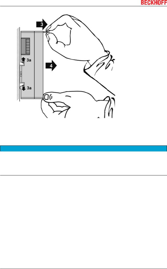
Demounting
•Remove all the cables.
•Lever the unlatching hook back with thumb and forefinger (3). An internal mechanism pulls the two latching lugs (3a) from the top hat rail back into the terminal module.
EL6090 |
Version: 2.6 |
27 |
Mounting and wiring
•Pull (4) the terminal module away from the mounting surface.
Avoid canting of the module; you should stabilize the module with the other hand, if required.
4.4Installation positions
NOTE
Constraints regarding installation position and operating temperature range
Please refer to the technical data for a terminal to ascertain whether any restrictions regarding the installation position and/or the operating temperature range have been specified. When installing high power dissipation terminals ensure that an adequate spacing is maintained between other components above and below the terminal in order to guarantee adequate ventilation!
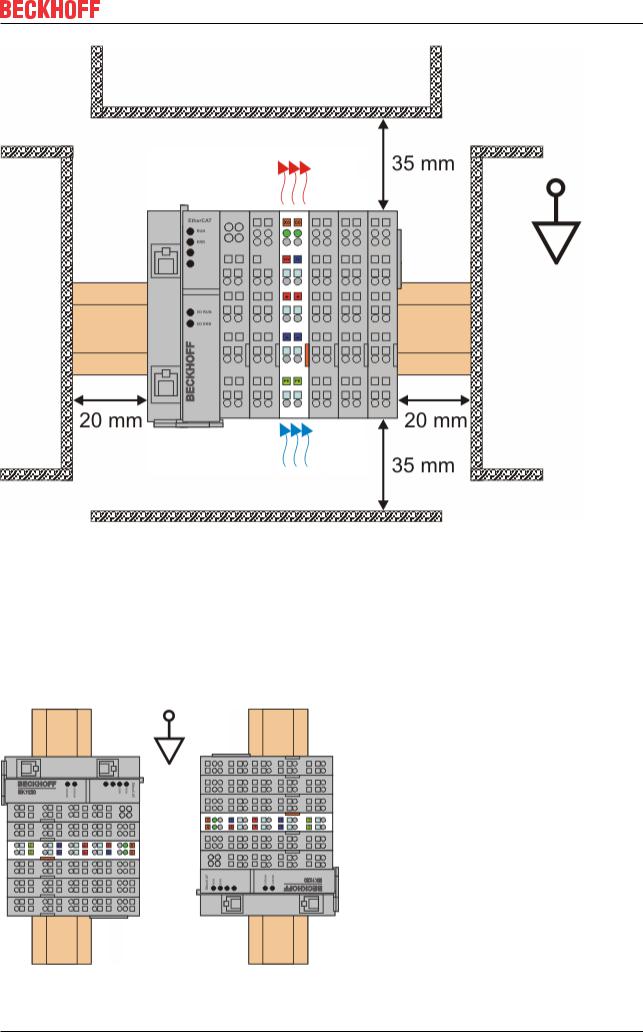
Optimum installation position (standard)
The optimum installation position requires the mounting rail to be installed horizontally and the connection surfaces of the EL/KL terminals to face forward (see Fig. Recommended distances for standard installation position). The terminals are ventilated from below, which enables optimum cooling of the electronics through convection. “From below” is relative to the acceleration of gravity.
28 |
Version: 2.6 |
EL6090 |
Mounting and wiring
Fig. 19: Recommended distances for standard installation position
Compliance with the distances shown in Fig. Recommended distances for standard installation position is recommended.
Other installation positions
All other installation positions are characterized by different spatial arrangement of the mounting rail - see Fig Other installation positions.
The minimum distances to ambient specified above also apply to these installation positions.
EL6090 |
Version: 2.6 |
29 |
Mounting and wiring
Fig. 20: Other installation positions
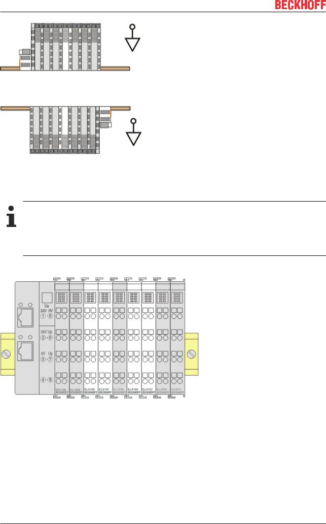
4.5Positioning of passive Terminals
Hint for positioning of passive terminals in the bus terminal block
EtherCAT Terminals (ELxxxx / ESxxxx), which do not take an active part in data transfer within the bus terminal block are so called passive terminals. The passive terminals have no current consumption out of the E-Bus.
To ensure an optimal data transfer, you must not directly string together more than two passive terminals!
Examples for positioning of passive terminals (highlighted)
Fig. 21: Correct positioning
30 |
Version: 2.6 |
EL6090 |
Loading...