


 Loading...
Hardware Data Sheet Section I
 Slave Controller
Section I – Technology
EtherCAT Protocol, Physical Layer,
EtherCAT Processing Unit, FMMU,
SyncManager, SII EEPROM, Distributed
Clocks
Section II – Register Description
(Online at http://www.beckhoff.com)
Section III – Hardware Description
(Online at http://www.beckhoff.com)
Version 2.2
Date: 2014-07-07

DOCUMENT ORGANIZATION
DOCUMENT ORGANIZATION
The Beckhoff EtherCAT Slave Controller (ESC) documentation covers the following Beckhoff ESCs:
ET1200
ET1100
EtherCAT IP Core for Altera® FPGAs
EtherCAT IP Core for Xilinx® FPGAs
ESC20
The documentation is organized in three sections. Section I and section II are common for all Beckhoff ESCs, Section III is specific for each ESC variant.
The latest documentation is available at the Beckhoff homepage (http://www.beckhoff.com).
Section I – Technology (All ESCs)
Section I deals with the basic EtherCAT technology. Starting with the EtherCAT protocol itself, the frame processing inside EtherCAT slaves is described. The features and interfaces of the physical layer with its two alternatives Ethernet and EBUS are explained afterwards. Finally, the details of the functional units of an ESC like FMMU, SyncManager, Distributed Clocks, Slave Information Interface, Interrupts, Watchdogs, and so on, are described.
Since Section I is common for all Beckhoff ESCs, it might describe features which are not available in a specific ESC. Refer to the feature details overview in Section III of a specific ESC to find out which features are available.
Section II – Register Description (All ESCs)
Section II contains detailed information about all ESC registers. This section is also common for all Beckhoff ESCs, thus registers, register bits, or features are described which might not be available in a specific ESC. Refer to the register overview and to the feature details overview in Section III of a specific ESC to find out which registers and features are available.
Section III – Hardware Description (Specific ESC)
Section III is ESC specific and contains detailed information about the ESC features, implemented registers, configuration, interfaces, pinout, usage, electrical and mechanical specification, and so on. Especially the Process Data Interfaces (PDI) supported by the ESC are part of this section.
Additional Documentation
Application notes and utilities like pinout configuration tools for ET1100/ET1200 can also be found at the Beckhoff homepage.
Trademarks
Beckhoff®, TwinCAT®, EtherCAT®, Safety over EtherCAT®, TwinSAFE® and XFC® are registered trademarks of and licensed by Beckhoff Automation GmbH. Other designations used in this publication may be trademarks whose use by third parties for their own purposes could violate the rights of the owners.
Patent Pending
The EtherCAT Technology is covered, including but not limited to the following German patent applications and patents: DE10304637, DE102004044764, DE102005009224, DE102007017835 with corresponding applications or registrations in various other countries.
Disclaimer
The documentation has been prepared with care. The products described are, however, constantly under development. For that reason the documentation is not in every case checked for consistency with performance data, standards or other characteristics. In the event that it contains technical or editorial errors, we retain the right to make alterations at any time and without warning. No claims for the modification of products that have already been supplied may be made on the basis of the data, diagrams and descriptions in this documentation.
Copyright
© Beckhoff Automation GmbH 07/2014.
The reproduction, distribution and utilization of this document as well as the communication of its contents to others without express authorization are prohibited. Offenders will be held liable for the payment of damages. All rights reserved in the event of the grant of a patent, utility model or design.
I-II |
Slave Controller – Technology |

DOCUMENT HISTORY
DOCUMENT HISTORY
Version Comment
1.0Initial release
1.1Chapter Interrupts – AL Event Request: corrected AL Event Mask register
address to 0x0204:0x0207
EtherCAT Datagram: Circulating Frame bit has position 14 (not 13)
PHY addressing configuration changed
Loop control: a port using Auto close mode is automatically opened if a valid Ethernet frame is received at this port
EEPROM read/write/reload example: steps 1 and 2 swapped
EEPROM: Configured Station Alias (0x0012:0x0013) is only taken over at first EEPROM load after power-on or reset
SyncManager: Watchdog trigger and interrupt generation in mailbox mode with single byte buffers requires alternating write and read accesses for some ESCs, thus buffered mode is required for Digital I/O watchdog trigger generation
National Semiconductor DP83849I Ethernet PHY deprecated because of large link loss reaction time and delay
Added distinction between permanent ports and Bridge port (frame processing)
Added PDI chapter
PDI and DC Sync/Latch signals are high impedance until the SII EEPROM is successfully loaded
Editorial changes
1.2PHY address configuration revised. Refer to Section III for ESC supported configurations
Added Ethernet Link detection chapter
Added MI Link Detection and Configuration, link detection descriptions updated
Added EEPROM Emulation for EtherCAT IP Core
Added General Purpose Input chapter
Corrected minimum datagram sizes in EtherCAT header figure
Editorial changes
1.2.1Chapter 5.1.1: incompatible PHYs in footnote 1 deleted
1.3Added advisory for unused MII/RMII/EBUS ports
Ethernet PHY requirements revised: e.g., configuration by strapping options, recommendations enhanced. Footnote about compatible PHYs removed, information has moved to the EtherCAT Slave Controller application note “PHY Selection Guide”.
Frame Error detection chapter enhanced
FIFO size reduction chapter enhanced
EBUS enhanced link detection chapter enhanced
Ethernet PHY link loss reaction time must be faster than 15 µs, otherwise use Enhanced link detection
Enhanced link detection description corrected. Enhanced link detection does not remain active if it is disabled by EEPROM and EBUS handshake frames are received
ARMW/FRWM commands increase the working counter by 1
Editorial changes
1.4Update to EtherCAT IP Core Release 2.1.0/2.01a
Added restriction to enhanced link configuration: RX_ER has to be asserted outside of frames (IEEE802 optional feature)
ESC power-on sequence for IP Core corrected
Removed footnote on tDiff figures, refer to Section III for actual figures
Editorial changes
Slave Controller – Technology |
I-III |

DOCUMENT HISTORY
Version Comment
1.5EEPROM Read/Write/Reload example: corrected register addresses
Updated/clarified PHY requirements, PHY link loss reaction time is mandatory
Enhanced Link Detection can be configured port-wise depending on ESC
Added DC Activation and DC Activation State features for some ESCs
ESC10 removed
Editorial changes
1.6Fill reserved EEPROM words of the ESC Configuration Area with 0
Interrupt chapter: example for proper interrupt handling added
Use Position Addressing only for bus scanning at startup and to detect newly attached devices
System Time PDI controlled: detailed description added
Added MII back-to-back connection example
Renamed Err(x) LED to PERR(x)
Editorial changes
1.7Link status description enhanced
Clarifications for DC System Time and reference between clocks and registers
Chapter on avoiding unconnected Port 0 configurations added
Direct ESC to standard Ethernet MAC MII connection added
MI link detection and configuration must not be used without LINK_MII signals
Added criteria for detecting when DC synchronization is established
SII EEPROM interface is a point-to-point connection
PHY requirements: PHY startup should not rely on MDC clocking, ESD tolerance and baseline wander compensation recommendations added
Editorial changes
1.8Update to EtherCAT IP Core Release 2.3.0/2.03a
EEPROM acknowledge error (0x0502[13]) can also occur for a read access
ERR and STATE LED updated
Editorial changes
1.9EtherCAT state machine: additional AL status codes defined
EtherCAT protocol: LRD/LRW read data depends on bit mask
Updated EBUS Enhanced Link Detection
Updated FMMU description
Loop control description updated
EtherCAT frame format (VLAN tag) description enhanced
Update to EtherCAT IP Core Release 2.3.2/2.03c
2.0Update to EtherCAT IP Core Release 2.4.0/2.04a
SII/ESI denotation now consistent with ETG
Updated AL Status codes
Editorial changes
2.1Update to EtherCAT IP Core Release 3.0.0/3.00a
Update to ET1100-0003 and ET1200-0003
RUN/ERR LED description enhanced
Added RGMII and FX operation
Added Gigabit Ethernet PHY chapter
Updated FIFO size configuration (default from SII)
Updated PHY address configuration
Added PDI register function acknowledge by write
Added propagation delay measurement in reverse mode (especially ET1200)
Enhanced ERR_LED description
Editorial changes
2.2Update to EtherCAT IP Core Release 3.0.6/3.00g
Added resetting Distributed Clocks Time Loop Control filters to the synchronization steps
Extended Back-to-Back MII connection schematic
Clarified EBUS standard link detection restrictions
Editorial changes
I-IV |
Slave Controller – Technology |

DOCUMENT HISTORY
Slave Controller – Technology |
I-V |

CONTENTS
|
|
|
CONTENTS |
|
1 |
EtherCAT Slave Controller Overview |
1 |
||
|
1.1 |
EtherCAT Slave Controller Function Blocks |
2 |
|
|
1.2 |
Further Reading on EtherCAT and ESCs |
3 |
|
|
1.3 |
Scope of Section I |
3 |
|
2 |
EtherCAT Protocol |
|
4 |
|
|
2.1 |
EtherCAT Header |
4 |
|
|
2.2 |
EtherCAT Datagram |
5 |
|
|
2.3 |
EtherCAT Addressing Modes |
6 |
|
|
|
2.3.1 |
Device Addressing |
7 |
|
|
2.3.2 |
Logical Addressing |
7 |
|
2.4 |
Working Counter |
8 |
|
|
2.5 |
EtherCAT Command Types |
9 |
|
3 |
Frame Processing |
|
12 |
|
|
3.1 |
Loop Control and Loop State |
12 |
|
|
3.2 |
Frame Processing Order |
14 |
|
|
3.3 |
Permanent Ports and Bridge Port |
15 |
|
|
3.4 |
Shadow Buffer for Register Write Operations |
15 |
|
|
3.5 |
Circulating Frames |
15 |
|
|
|
3.5.1 |
Unconnected Port 0 |
16 |
|
3.6 |
Non-EtherCAT Protocols |
16 |
|
|
3.7 |
Special Functions of Port 0 |
16 |
|
4 |
Physical Layer Common Features |
17 |
||
|
4.1 |
Link Status |
17 |
|
|
4.2 |
Selecting Standard/Enhanced Link Detection |
18 |
|
|
4.3 |
FIFO Size Reduction |
19 |
|
|
4.4 |
Frame Error Detection |
19 |
|
5 |
Ethernet Physical Layer |
20 |
||
|
5.1 |
Requirements to Ethernet PHYs |
20 |
|
|
5.2 |
PHY reset and Link partner notification/loop closing |
20 |
|
|
5.3 |
MII Interface |
21 |
|
|
5.4 |
RMII Interface |
22 |
|
|
5.5 |
RGMII Interface |
22 |
|
|
|
5.5.1 |
RGMII In-Band Link Status |
22 |
|
5.6 |
Link Detection |
22 |
|
|
|
5.6.1 |
LINK_MII Signal |
22 |
|
|
5.6.2 |
MI Link Detection and Configuration |
23 |
|
5.7 |
Standard and Enhanced MII Link Detection |
23 |
|
|
5.8 |
EtherCAT over Optical Links (FX) |
24 |
|
|
|
5.8.1 |
Link partner notification and loop closing |
24 |
|
|
|
|
|
I-VI |
|
|
|
Slave Controller – Technology |

|
|
|
|
CONTENTS |
|
|
5.8.2 |
Far-End-Fault (FEF) |
24 |
|
|
5.8.3 |
ESCs with native FX support |
25 |
|
|
5.8.4 |
ESCs without native FX support |
25 |
|
5.9 |
Gigabit Ethernet PHYs |
25 |
|
|
5.10 |
MII Management Interface (MI) |
26 |
|
|
|
5.10.1 |
PHY Addressing/PHY Address Offset |
26 |
|
|
5.10.2 |
Logical Interface |
28 |
|
|
5.10.3 |
MI Protocol |
29 |
|
|
5.10.4 |
Timing specifications |
29 |
|
5.11 |
MII management example schematic |
30 |
|
|
5.12 |
Ethernet Termination and Grounding Recommendation |
31 |
|
|
5.13 |
Ethernet Connector (RJ45 / M12) |
32 |
|
|
5.14 |
Back-to-Back MII Connection |
33 |
|
|
|
5.14.1 |
ESC to ESC Connection |
33 |
|
|
5.14.2 |
ESC to Standard Ethernet MAC |
34 |
6 |
EBUS/LVDS Physical Layer |
35 |
||
|
6.1 |
Interface |
|
35 |
|
6.2 |
EBUS Protocol |
36 |
|
|
6.3 |
Timing Characteristics |
36 |
|
|
6.4 |
Standard EBUS Link Detection |
37 |
|
|
6.5 |
Enhanced EBUS Link Detection |
37 |
|
|
6.6 |
EBUS RX Errors |
38 |
|
|
6.7 |
EBUS Low Jitter |
38 |
|
|
6.8 |
EBUS Connection |
38 |
|
7 |
FMMU |
|
|
39 |
8 |
SyncManager |
|
41 |
|
|
8.1 |
Buffered Mode |
42 |
|
|
8.2 |
Mailbox Mode |
43 |
|
|
|
8.2.1 |
Mailbox Communication Protocols |
43 |
|
8.3 |
PDI register function acknowledge by Write |
44 |
|
|
8.4 |
Interrupt and Watchdog Trigger Generation, Latch Event Generation |
44 |
|
|
8.5 |
Single Byte Buffer Length / Watchdog Trigger for Digital Output PDI |
45 |
|
|
8.6 |
Repeating Mailbox Communication |
45 |
|
|
8.7 |
SyncManager Deactivation by the PDI |
46 |
|
9 |
Distributed Clocks |
|
47 |
|
|
9.1 |
Clock Synchronization |
47 |
|
|
|
9.1.1 |
Clock Synchronization Process |
49 |
|
|
9.1.2 |
Propagation Delay Measurement |
50 |
|
|
9.1.3 |
Offset Compensation |
55 |
|
|
9.1.4 |
Resetting the Time Control Loop |
56 |
|
|
9.1.5 |
Drift Compensation |
56 |
|
|
|
||
|
Slave Controller – Technology |
I-VII |
||

CONTENTS
|
|
9.1.6 |
Reference between DC Registers/Functions and Clocks |
58 |
|
|
9.1.7 |
When is Synchronization established? |
59 |
|
|
9.1.8 |
Clock Synchronization Initialization Example |
59 |
|
9.2 |
SyncSignals and LatchSignals |
60 |
|
|
|
9.2.1 |
Interface |
60 |
|
|
9.2.2 |
Configuration |
60 |
|
|
9.2.3 |
SyncSignal Generation |
61 |
|
|
9.2.4 |
LatchSignals |
64 |
|
|
9.2.5 |
ECAT or PDI Control |
65 |
|
9.3 |
System Time PDI Controlled |
66 |
|
|
9.4 |
Communication Timing |
68 |
|
10 |
EtherCAT State Machine |
70 |
||
|
10.1 |
EtherCAT State Machine Registers |
71 |
|
|
|
10.1.1 |
AL Control and AL Status Register |
71 |
|
|
10.1.2 |
Device Emulation |
71 |
|
|
10.1.3 |
Error Indication and AL Status Code Register |
71 |
11 |
SII EEPROM |
|
72 |
|
|
11.1 |
SII EEPROM Content |
73 |
|
|
11.2 |
SII EEPROM Logical Interface |
74 |
|
|
|
11.2.1 |
SII EEPROM Errors |
75 |
|
|
11.2.2 |
SII EEPROM Interface Assignment to ECAT/PDI |
76 |
|
|
11.2.3 |
Read/Write/Reload Example |
77 |
|
|
11.2.4 |
EEPROM Emulation |
77 |
|
11.3 |
SII EEPROM Electrical Interface (I2C) |
78 |
|
|
|
11.3.1 |
Addressing |
78 |
|
|
11.3.2 |
EEPROM Size |
78 |
|
|
11.3.3 |
I²C Access Protocol |
79 |
|
|
11.3.4 |
Timing specifications |
80 |
12 |
Interrupts |
|
|
82 |
|
12.1 |
AL Event Request (PDI Interrupt) |
82 |
|
|
12.2 |
ECAT Event Request (ECAT Interrupt) |
83 |
|
|
12.3 |
Clearing Interrupts Accidentally |
83 |
|
13 |
Watchdogs |
|
|
84 |
|
13.1 |
Process Data Watchdog |
84 |
|
|
13.2 |
PDI Watchdog |
84 |
|
14 |
Error Counters |
|
85 |
|
|
14.1 |
Frame error detection |
86 |
|
|
14.2 |
Errors and Forwarded Errors |
86 |
|
15 |
LED Signals (Indicators) |
87 |
||
|
15.1 |
RUN LED |
87 |
|
|
|
15.1.1 |
RUN LED override |
87 |
|
|
|
|
|
I-VIII |
|
|
Slave Controller – Technology |
|

|
|
|
|
CONTENTS |
|
15.2 |
ERR LED |
88 |
|
|
|
15.2.1 |
ERR LED override |
88 |
|
15.3 |
STATE LED and STATE_RUN LED Signal |
89 |
|
|
15.4 |
LINKACT LED |
89 |
|
|
15.5 |
Port Error LED (PERR) |
90 |
|
16 Process Data Interface (PDI) |
91 |
|||
|
16.1 |
PDI Selection and Configuration |
91 |
|
|
16.2 |
PDI register function acknowledge by write |
92 |
|
|
16.3 |
General Purpose I/O |
93 |
|
|
|
16.3.1 |
General Purpose Inputs |
93 |
|
|
16.3.2 |
General Purpose Output |
93 |
17 |
Additional Information |
|
94 |
|
|
17.1 |
ESC Clock Source |
94 |
|
|
17.2 |
Power-on Sequence |
94 |
|
|
17.3 |
Write Protection |
95 |
|
|
|
17.3.1 |
Register Write Protection |
95 |
|
|
17.3.2 |
ESC Write Protection |
95 |
|
17.4 |
ESC Reset |
95 |
|
18 |
Appendix |
|
|
96 |
|
18.1 |
Support and Service |
96 |
|
|
|
18.1.1 Beckhoff’s branch offices and representatives |
96 |
|
|
18.2 |
Beckhoff Headquarters |
96 |
|
Slave Controller – Technology |
I-IX |

TABLES |
|
|
TABLES |
|
|
Table 1: ESC Main Features ................................................................................................................... |
|
1 |
Table 2: EtherCAT Frame Header........................................................................................................... |
|
4 |
Table 3: EtherCAT Datagram .................................................................................................................. |
|
6 |
Table 4: EtherCAT Addressing Modes .................................................................................................... |
|
6 |
Table 5: Working Counter Increment ...................................................................................................... |
|
8 |
Table 6: EtherCAT Command Types .................................................................................................... |
|
10 |
Table 7: EtherCAT Command Details ................................................................................................... |
|
11 |
Table 8: Registers for Loop Control and Loop/Link Status ................................................................... |
|
13 |
Table 9: Frame Processing Order ......................................................................................................... |
|
14 |
Table 10: Link Status Description.......................................................................................................... |
|
17 |
Table 11: Registers for Enhanced Link Detection ................................................................................. |
|
18 |
Table 12: Registers for FIFO Size Reduction........................................................................................ |
|
19 |
Table 13: Special/Unused MII Interface signals .................................................................................... |
|
21 |
Table 14: Registers used for Ethernet Link Detection........................................................................... |
|
22 |
Table 15: PHY Address configuration matches PHY address settings................................................. |
|
27 |
Table 16: PHY Address configuration does not match actual PHY address settings ........................... |
27 |
|
Table 17: MII Management Interface Register Overview ...................................................................... |
|
28 |
Table 18: MII Management Interface timing characteristics.................................................................. |
|
29 |
Table 19: Signals used for Fast Ethernet .............................................................................................. |
|
32 |
Table 20: EBUS Interface signals ......................................................................................................... |
|
35 |
Table 21: EBUS timing characteristics .................................................................................................. |
|
36 |
Table 22: Example FMMU Configuration .............................................................................................. |
|
39 |
Table 23: SyncManager Register overview........................................................................................... |
|
41 |
Table 24: EtherCAT Mailbox Header .................................................................................................... |
|
44 |
Table 25: Registers for Propagation Delay Measurement .................................................................... |
|
50 |
Table 26: Parameters for Propagation Delay Calculation ..................................................................... |
|
53 |
Table 27: Registers for Offset Compensation ....................................................................................... |
|
55 |
Table 28: Registers for Resetting the Time Control Loop ..................................................................... |
|
56 |
Table 29: Registers for Drift Compensation .......................................................................................... |
|
57 |
Table 30: Reference between DC Registers/Functions and Clocks ..................................................... |
|
58 |
Table 31: Distributed Clocks signals ..................................................................................................... |
|
60 |
Table 32: SyncSignal Generation Mode Selection................................................................................ |
|
61 |
Table 33: Registers for SyncSignal Generation .................................................................................... |
|
62 |
Table 34: Registers for Latch Input Events ........................................................................................... |
|
65 |
Table 35: Registers for the EtherCAT State Machine ........................................................................... |
|
71 |
Table 36: AL Control and AL Status Register Values ........................................................................... |
|
71 |
Table 37: ESC Configuration Area ........................................................................................................ |
|
73 |
Table 38: SII EEPROM Content Excerpt............................................................................................... |
|
74 |
Table 39: SII EEPROM Interface Register Overview ............................................................................ |
|
74 |
Table 40: SII EEPROM Interface Errors................................................................................................ |
|
75 |
Table 41: I²C EEPROM signals ............................................................................................................. |
|
78 |
Table 42: EEPROM Size ....................................................................................................................... |
|
78 |
Table 43: I²C Control Byte ..................................................................................................................... |
|
79 |
Table 44: I²C Write Access.................................................................................................................... |
|
79 |
Table 45: I²C Read Access.................................................................................................................... |
|
80 |
Table 46: EEPROM timing characteristics ............................................................................................ |
|
80 |
Table 47: Registers for AL Event Request Configuration ..................................................................... |
|
82 |
Table 48: Registers for ECAT Event Request Configuration ................................................................ |
|
83 |
Table 49: Registers for Watchdogs ....................................................................................................... |
|
84 |
Table 50: Error Counter Overview......................................................................................................... |
|
85 |
Table 51: Errors Detected by Physical Layer, Auto-Forwarder, and EtherCAT Processing Unit ......... |
86 |
|
Table 52: RUN LED state indication...................................................................................................... |
|
87 |
Table 53: Registers for RUN LED control ............................................................................................. |
|
87 |
Table 54: Automatic ESC ERR LED state indication ............................................................................ |
|
88 |
Table 55: Registers for ERR LED control.............................................................................................. |
|
88 |
Table 56: LINKACT LED States ............................................................................................................ |
|
89 |
Table 57: Available PDIs depending on ESC ........................................................................................ |
|
91 |
Table 58: Functions/registers affected by PDI register function acknowledge by write ........................ |
92 |
|
Table 59: ESC Power-On Sequence..................................................................................................... |
|
94 |
Table 60: Registers for Write Protection ............................................................................................... |
|
95 |
I-X |
Slave Controller – Technology |
|
TABLES
Slave Controller – Technology |
I-XI |

FIGURES |
|
FIGURES |
|
Figure 1: EtherCAT Slave Controller Block Diagram .............................................................................. |
1 |
Figure 2: Ethernet Frame with EtherCAT Data ....................................................................................... |
4 |
Figure 3: EtherCAT Datagram................................................................................................................. |
5 |
Figure 4: Auto close loop state transitions ............................................................................................ |
13 |
Figure 5: Frame Processing .................................................................................................................. |
14 |
Figure 6: Circulating Frames ................................................................................................................. |
15 |
Figure 7: All frames are dropped because of Circulating Frame Prevention ........................................ |
16 |
Figure 8: Write access........................................................................................................................... |
29 |
Figure 9: Read access........................................................................................................................... |
29 |
Figure 10: MII management example schematic .................................................................................. |
30 |
Figure 11: Termination and Grounding Recommendation .................................................................... |
31 |
Figure 12: RJ45 Connector ................................................................................................................... |
32 |
Figure 13: M12 D-code Connector ........................................................................................................ |
32 |
Figure 14: Back-to-Back MII Connection (two ESCs) ........................................................................... |
33 |
Figure 15: Back-to-Back MII Connection (ESC and standard MAC)..................................................... |
34 |
Figure 16: EBUS Interface Signals........................................................................................................ |
35 |
Figure 17: EBUS Protocol ..................................................................................................................... |
36 |
Figure 18: Example EtherCAT Network ................................................................................................ |
37 |
Figure 19: EBUS Connection ................................................................................................................ |
38 |
Figure 20: FMMU Mapping Principle ..................................................................................................... |
39 |
Figure 21: FMMU Mapping Example..................................................................................................... |
40 |
Figure 22: SyncManager Buffer allocation ............................................................................................ |
42 |
Figure 23: SyncManager Buffered Mode Interaction............................................................................. |
42 |
Figure 24: SyncManager Mailbox Interaction ........................................................................................ |
43 |
Figure 25: EtherCAT Mailbox Header (for all Types) ............................................................................ |
44 |
Figure 26: Handling of a Repeat Request with Read Mailbox .............................................................. |
46 |
Figure 27: Propagation Delay, Offset, and Drift Compensation ............................................................ |
49 |
Figure 28: Propagation Delay Calculation ............................................................................................. |
52 |
Figure 29: Distributed Clocks signals .................................................................................................... |
60 |
Figure 30: SyncSignal Generation Modes............................................................................................. |
61 |
Figure 31: SYNC0/1 Cycle Time Examples .......................................................................................... |
63 |
Figure 32: System Time PDI Controlled with three steps ..................................................................... |
66 |
Figure 33: System Time PDI Controlled with two steps ........................................................................ |
67 |
Figure 34: DC Timing Signals in relation to Communication................................................................. |
68 |
Figure 35: EtherCAT State Machine ..................................................................................................... |
70 |
Figure 36: SII EEPROM Layout............................................................................................................. |
72 |
Figure 37: I²C EEPROM signals............................................................................................................ |
78 |
Figure 38: Write access (1 address byte, up to 16 Kbit EEPROMs)..................................................... |
80 |
Figure 39: Write access (2 address bytes, 32 Kbit - 4 Mbit EEPROMs) ............................................... |
81 |
Figure 40: Read access (1 address byte, up to 16 Kbit EEPROMs) .................................................... |
81 |
Figure 41: PDI Interrupt Masking and interrupt signals ......................................................................... |
82 |
Figure 42: ECAT Interrupt Masking ....................................................................................................... |
83 |
I-XII |
Slave Controller – Technology |

ABBREVIATIONS
|
ABBREVIATIONS |
|
µC |
Microcontroller |
|
ADR |
Address |
|
ADS |
Automation Device Specification (Beckhoff) |
|
AL |
Application Layer |
|
AMBA® |
Advanced Microcontroller Bus Architecture from ARM® |
|
APRD |
Auto Increment Physical Read |
|
APWR |
Auto Increment Physical Write |
|
APRW |
Auto Increment Physical ReadWrite |
|
ARMW |
Auto Increment Physical Read Multiple Write |
|
AoE |
ADS over EtherCAT |
|
ASIC |
Application Specific Integrated Chip |
|
Auto Crossover |
Automatic detection of whether or not the send and receive lines are crossed. |
|
Auto Negotiation |
Automatic negotiation of transmission speeds between two stations. |
|
Avalon® |
On-chip bus for Altera® FPGAs |
|
AXITM |
Advanced eXtensible Interface Bus, an AMBA interconnect. Used as On-Chip- |
|
|
bus |
|
Big Endian |
Data format (also Motorola format). The more significant byte is transferred first |
|
|
when a word is transferred. However, for EtherCAT the least significant bit is |
|
|
the first on the wire. |
|
BOOT |
BOOT state of EtherCAT state machine |
|
Boundary Clock |
A station that is synchronized by another station and then passes this |
|
|
information on. |
|
Bridge |
A term for switches used in standards. Bridges are devices that pass on |
|
|
messages based on address information. |
|
Broadcast |
An unacknowledged transmission to an unspecified number of receivers. |
|
BRD |
Broadcast Read |
|
BWR |
Broadcast Write |
|
BRW |
Broadcast ReadWrite |
|
Cat |
Category – classification for cables that is also used in Ethernet. Cat 5 is the |
|
|
minimum required category for EtherCAT. However, Cat 6 and Cat 7 cables are |
|
|
available. |
|
CoE |
CAN® application layer over EtherCAT |
|
Communication |
A communication software package that is generally divided into successive |
|
Stack |
layers, which is why it is referred to as a stack. |
|
Confirmed |
Means that the initiator of a service receives a response. |
|
CRC |
Cyclic Redundancy Check, used for FCS |
|
|
|
|
Slave Controller – Technology |
I-XIII |
|

ABBREVIATIONS
Cut Through |
Procedure for cutting directly through an Ethernet frame by a switch before the |
|
complete message is received. |
Cycle |
Cycle in which data is to be exchanged in a system operating on a periodical |
|
basis. |
DC |
Distributed Clocks |
|
Mechanism to synchronize EtherCAT slaves and master |
Delay |
Delays can be caused by run-times during transfer or internal delays of a |
|
network component. |
Dest Addr |
Destination address of a message (the destination can be an individual network |
|
station or a group (multicast). |
DHCP |
Dynamic Host Configuration Protocol, used to assign IP addresses (and other |
|
important startup parameter in the Internet context). |
DL |
Data Link Layer, also known as Layer 2. EtherCAT uses the Data Link Layer of |
|
Ethernet, which is standardized as IEEE 802.3. |
DNS |
Domain Name Service, a protocol for domain name to IP addresses resolution. |
EBUS |
Based on LVDS (Low Voltage Differential Signaling) standard specified in |
|
ANSI/TIA/EIA-644-1995 |
ECAT |
EtherCAT |
EEPROM |
Electrically Erasable Programmable Read Only Memory. Non-volatile memory |
|
used to store EtherCAT Slave Information (ESI). Connected to the SII. |
EMC |
Electromagnetic Compatibility, describes the robustness of a device with regard |
|
to electrical interference from the environment. |
EMI |
Electromagnetic Interference |
Engineering |
Here: All applications required to configure and program a machine. |
EoE |
Ethernet over EtherCAT |
EOF |
End of Frame |
ERR |
Error indicator for AL state |
Err(x) |
Physical Layer RX Error LED for debugging purposes |
ESC |
EtherCAT Slave Controller |
ESI |
EtherCAT Slave Information, stored in SII EEPROM |
ESM |
EtherCAT State Machine |
ETG |
EtherCAT Technology Group (http://www.ethercat.org) |
EtherCAT |
Real-time Standard for Industrial Ethernet Control Automation Technology |
|
(Ethernet for Control Automation Technology) |
EtherType |
Identification of an Ethernet frame with a 16-bit number assigned by IEEE. For |
|
example, IP uses EtherType 0x0800 (hexadecimal) and the EtherCAT protocol |
|
uses 0x88A4. |
|
|
I-XIV |
Slave Controller – Technology |

|
ABBREVIATIONS |
|
EPU |
EtherCAT Processing Unit. The logic core of an ESC containing e.g. registers, |
|
|
memory, and processing elements. |
|
Fast Ethernet |
Ethernet with a transmission speed of 100 Mbit/s. |
|
FCC |
Federal Communications Commission |
|
FCS |
Frame Check Sequence |
|
FIFO |
First In First Out |
|
Firewall |
Routers or other network component that acts as a gateway to the Internet and |
|
|
enables protection from unauthorized access. |
|
FMMU |
Fieldbus Memory Management Unit |
|
FoE |
File access over EtherCAT |
|
Follow Up |
Message that follows Sync and indicates when the Sync frame was sent from |
|
|
the last node (defined in IEEE 1588). |
|
FPGA |
Field Programmable Gate Array |
|
FPRD |
Configured Address Physical Read |
|
FPWR |
Configured Address Physical Write |
|
FPRW |
Configured Address Physical ReadWrite |
|
FRMW |
Configured Address Physical Read Multiple Write |
|
Frame |
See PDU |
|
FTP |
File Transfer Protocol |
|
Get |
Access method used by a client to read data from a device. |
|
GND |
Ground |
|
GPI |
General Purpose Input |
|
GPO |
General Purpose Output |
|
HW |
Hardware |
|
I²C |
Inter-Integrated Circuit, serial bus used for SII EEPROM connection |
|
ICMP |
Internet Control Message Protocol: Mechanisms for signaling IP errors. |
|
IEC |
International Electrotechnical Commission |
|
IEEE |
Institute of Electrical and Electronics Engineers |
|
INIT |
INIT state of EtherCAT state machine |
|
Interval |
Time span |
|
IP |
Internet Protocol: Ensures transfer of data on the Internet from end node to end |
|
|
node. |
|
|
Intellectual Property |
|
IRQ |
Interrupt Request |
|
ISO |
International Standard Organization |
|
|
|
|
Slave Controller – Technology |
I-XV |
|

ABBREVIATIONS
ISO/OSI Model |
ISO Open Systems Interconnection Basic Reference Model (ISO 7498): |
|
describes the division of communication into 7 layers. |
IT |
Information Technology: Devices and methods required for computer-aided |
|
information processing. |
LatchSignal |
Signal for Distributed Clocks time stamping |
LED |
Light Emitting Diode, used as an indicator |
Link/Act |
Link/Activity Indicator (LED) |
Little Endian |
Data format (also Intel format). The less significant byte is transferred first when |
|
a word is transferred. With EtherCAT, the least significant bit is the first on the |
|
wire. |
LLDP |
Lower Layer Discovery Protocol – provides the basis for topology discovery and |
|
configuration definition (see IEEE802.1ab) |
LRD |
Logical Read |
LWR |
Logical Write |
LRW |
Logical ReadWrite |
LVDS |
Low Voltage Differential Signaling |
M12 |
Connector used for industrial Ethernet |
MAC |
Media Access Control: Specifies station access to a communication medium. |
|
With full duplex Ethernet, any station can send data at any time; the order of |
|
access and the response to overload are defined at the network component |
|
level (switches). |
MAC Address |
Media Access Control Address: Also known as Ethernet address; used to |
|
identify an Ethernet node. The Ethernet address is 6 bytes long and is assigned |
|
by the IEEE. |
Mandatory |
Mandatory services, parameters, objects, or attributes. These must be |
Services |
implemented by every station. |
MBX |
Mailbox |
MDI |
Media Dependent Interface: |
|
Use of connector Pins and Signaling (PC side) |
MDI-X |
Media Dependent Interface (crossed): |
|
Use of connector Pins and Signaling with crossed lines (Switch/hub side) |
MI |
(PHY) Management Interface |
MII |
Media Independent Interface: Standardized interface between the Ethernet |
|
MAC and PHY. |
Multicast |
Transmission to multiple destination stations with a frame – generally uses a |
|
special address. |
NOP |
No Operation |
NVRAM |
Non-volatile random access memory, e.g. EEPROM or Flash. |
Octet |
Term from IEC 61158 – one octet comprises exactly 8 bits. |
OP |
Operational state of EtherCAT state machine |
|
|
I-XVI |
Slave Controller – Technology |

|
ABBREVIATIONS |
|
OPB |
On-Chip Peripheral Bus |
|
Optional Service |
Optional services can be fulfilled by a PROFINET station in addition to the |
|
|
mandatory services. |
|
OSI |
Open System Interconnect |
|
OUI |
Organizationally Unique Identifier –the first 3 Bytes of an Ethernet-Address that |
|
|
will be assign to companies or organizations and can be used for protocol |
|
|
identifiers as well (e.g. LLDP) |
|
PDI |
Process Data Interface or Physical Device Interface: an interface that allows |
|
|
access to ESC from the process side. |
|
PDO |
Process Data Object |
|
PDU |
Protocol Data Unit: Contains protocol information (Src Addr, Dest Addr, |
|
|
Checksum and service parameter information) transferred from a protocol |
|
|
instance of transparent data to a subordinate level (the lower level contains the |
|
|
information being transferred). |
|
PE |
Protection Earth |
|
PHY |
Physical layer device that converts data from the Ethernet controller to electric |
|
|
or optical signals. |
|
Ping |
Frame that verifies whether the partner device is still available. |
|
PLB |
Processor Local Bus |
|
PLL |
Phase Locked Loop |
|
PREOP |
Pre-Operational state of EtherCAT state machine |
|
Priority Tagging |
Priority field inserted in an Ethernet frame. |
|
Protocol |
Rules for sequences – here, also the sequences (defined in state machines) |
|
|
and frame structures (described in encoding) of communication processes. |
|
Provider |
Device that sends data to other consumers in the form of a broadcast message. |
|
PTP |
Precision Time Protocol in accordance with IEEE 1588: Precise time |
|
|
synchronization procedures. |
|
PTP Master |
Indicates time in a segment. |
|
PTP Slave |
Station synchronized by a PTP master. |
|
Quad Cable |
Cable type in which the two cable pairs are twisted together. This strengthens |
|
|
the electromagnetic resistance. |
|
RAM |
Random Access Memory. ESC have User RAM and Process Data RAM. |
|
Read |
Service enabling read access to an I/O device. |
|
Real-Time |
Real-time capability of a system to perform a task within a specific time. |
|
Request |
Call of a service in the sender/client. |
|
Response |
Response to a service on the client side. |
|
|
|
|
Slave Controller – Technology |
I-XVII |
|

ABBREVIATIONS
RJ45 |
FCC Registered Jack, standard Ethernet connector (8P8C) |
RMII |
Reduced Media Independent Interface |
Router |
Network component acting as a gateway based on the interpretation of the IP |
|
address. |
RSTP |
Rapid Spanning Tree Protocol: Prevents packet from looping infinitely between |
|
switches; RSTP is specified in IEEE 802.1 D (Edition 2004) |
RT |
Real-time. Name for a real-time protocol that can be run in Ethernet controllers |
|
without special support. |
RTC |
Real-time Clock chip of PCs |
RT Frames |
EtherCAT Messages with EtherType 0x88A4. |
RX |
Receive |
RXPDO |
Receive PDO, i.e. Process Data that will be received by ESC20 |
RUN |
RUN indicator (LED) for application state |
SAFEOP |
Safe-Operational state of EtherCAT state machine |
Safety |
Safety function, implemented by an electric, electronic programmable fail-safe |
|
system that maintains the equipment in a safe state, even during certain critical |
|
external events. |
Schedule |
Determines what should be transferred and when. |
Services |
Interaction between two components to fulfill a specific task. |
Set |
Access method used by a client to write data to a server. |
SII |
Slave Information Interface |
SM |
SyncManager |
SNMP |
Simple Network Management Protocol: SNMP is the standard Internet protocol |
|
for management and diagnostics of network components (see also RFC 1157 |
|
and RFC 1156 at www.ietf.org ). |
SoE |
Servo Profile over EtherCAT |
SOF |
Start of Frame |
|
Ethernet SOF delimiter at the end of the preamble of Ethernet frames |
SPI |
Serial Peripheral Interface |
Src Addr |
Source Address: Source address of a message. |
Store and |
Currently the common operating mode in switches. Frames are first received in |
Forward |
their entirety, the addresses are evaluated, and then they are forwarded. This |
|
result in considerable delays, but guarantees that defective frames are not |
|
forwarded, causing an unnecessary increase in the bus load. |
STP |
Shielded Twisted Pair: Shielded cable with at least 2 core pairs to be used as |
|
the standard EtherCAT cable. |
|
|
I-XVIII |
Slave Controller – Technology |

|
ABBREVIATIONS |
Subnet Mask |
Divides the IP address into two parts: a subnet address (in an area separated |
|
from the rest by routers) and a network address. |
Switch |
Also known as Bridge. Active network component to connect different |
|
EtherCAT participants with each other. A switch only forwards the frames to the |
|
addressed participants. |
SyncManager |
ESC unit for coordinated data exchange between master and slave µController |
SyncSignal |
Signal generated by the Distributed Clocks unit |
TCP |
Transmission Control Protocol: Higher-level IP protocol that ensures secure |
|
data exchange and flow control. |
TX |
Transmit |
TXPDO |
Transmit PDO, i.e. Process Data that will be transmitted by ESC20 |
UDP |
User Datagram Protocol: Non-secure multicast/broadcast frame. |
UTP |
Unshielded Twisted Pair: Unshielded cable with at least 2 core pairs are not |
|
recommended for industrial purpose but are commonly used in areas with low |
|
electro-magnetic interference. |
VLAN |
Virtual LAN |
VoE |
Vendor specific profile over EtherCAT |
WD |
Watchdog |
WKC |
Working Counter |
XML |
Extensible Markup Language: Standardized definition language that can be |
|
interpreted by nearly all parsers. |
XML Parser |
Program for checking XML schemas. |
Slave Controller – Technology |
I-XIX |

EtherCAT Slave Controller Overview
1 EtherCAT Slave Controller Overview
An EtherCAT Slave Controller (ESC) takes care of the EtherCAT communication as an interface between the EtherCAT fieldbus and the slave application. This document covers the following Beckhoff ESCs: ASIC implementations (ET1100, ET1200), functionally fixed binary configurations for FPGAs (ESC20), and configurable IP Cores for FPGAs (ET1810/ET1815).
|
|
|
|
|
Table 1: ESC Main Features |
|
|
|
|
|
|
|
|
|
|||||
|
|
|
|
|
|
|
|
|
|
|
|
|
|
|
|
|
|
|
|
|
Feature |
|
|
|
ET1200 |
|
|
|
ET1100 |
|
|
|
IP Core |
|
|
|
ESC20 |
|
|
|
|
|
|
|
|
|
|
|
|
|
|
|
|
|
|||||
|
Ports |
|
|
|
2-3 (each |
|
|
|
2-4 (each |
|
|
|
1-3 MII/ |
|
|
|
2 MII |
|
|
|
|
|
|
|
EBUS/MII, |
|
|
|
EBUS/MII) |
|
|
|
1-3 |
RGMII/ |
|
|
|
|
|
|
|
|
|
|
max. 1xMII) |
|
|
|
|
|
|
|
1-2 |
RMII |
|
|
|
|
|
|
|
|
|
|
|
|
|
|
|
|
|||||||||
|
FMMUs |
|
|
|
3 |
|
|
|
8 |
|
|
|
0-8 |
|
|
|
|
4 |
|
|
|
|
|
|
|
|
|
|
|
|
|||||||||
|
SyncManagers |
|
|
|
4 |
|
|
|
8 |
|
|
|
0-8 |
|
|
|
|
4 |
|
|
|
|
|
|
|
|
|
|
|
||||||||||
|
RAM [Kbyte] |
|
|
|
1 |
|
|
|
8 |
|
|
|
0-60 |
|
|
|
4 |
|
|
|
|
|
|
|
|
|
|
|
|
|
|
|
|
|
|||||
|
Distributed Clocks |
|
|
|
64 bit |
|
|
|
64 bit |
|
|
|
32/64 bit |
|
|
|
32 bit |
|
|
|
|
|
|
|
|
|
|
|
|
|
|
|
|
|
|
|
|
|
|
|
Process Data Interfaces |
|
|
|
|
|
|
|
|
|
|
|
|
|
|
|
|
|
|
|
|
|
|
|
|
|
|
|
|
|
|
|
|
|
|
|
|
|
|
|
Digital I/O |
|
|
|
16 bit |
|
|
|
32 bit |
|
|
|
|
|
|
|
|
|
|
|
|
|
SPI Slave |
|
|
|
Yes |
|
|
|
Yes |
|
|
|
|
|
|
|
|
|
|||
|
8/16 bit µController |
|
|
|
- |
|
|
|
Async/Sync |
|
|
|
|
|
|
||||||
|
On-chip bus |
|
|
|
- |
|
|
|
- |
|
|
|
|
|
|
|
|
|
|
|
|
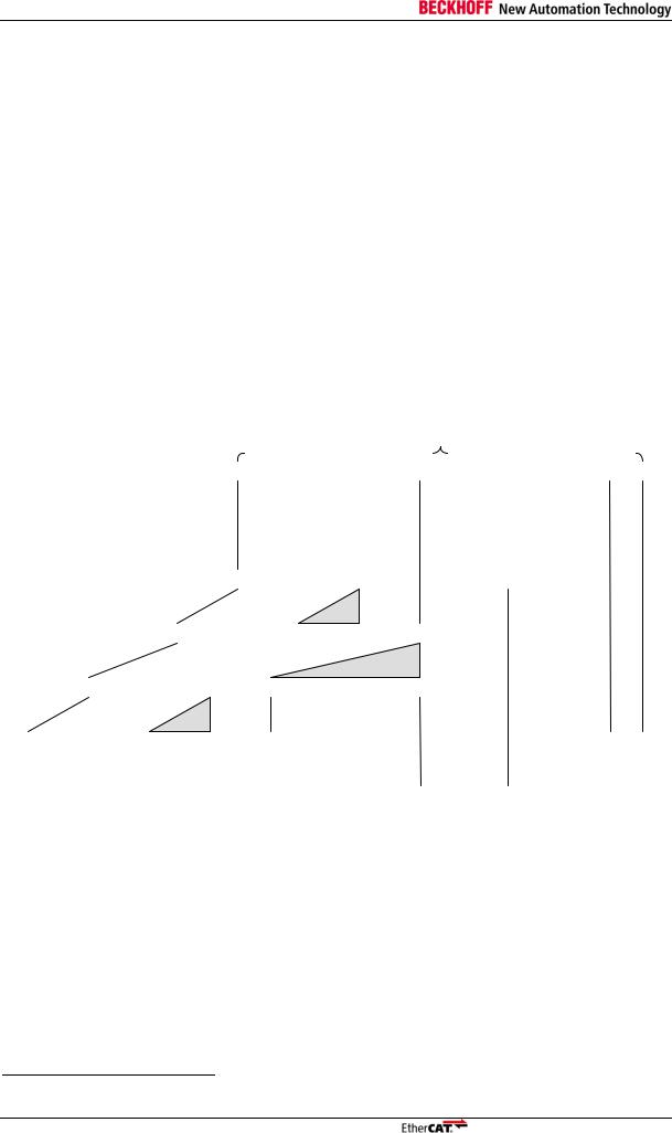
The general functionality of an ESC is shown in Figure 1:
Ports (Ethernet/EBUS)
0 1 2 3
|
AutoForwarder + |
PHY MI |
Loopback |
|
|
8-32 bit |
|
|
|
32 bit |
|
|
|
|
|
|
||
|
Yes |
|
|
|
Yes |
|
|
|
|
|
|
||
|
Async |
|
|
|
Async |
|
|
|
|
|
|||
|
Yes |
|
|
|
- |
|
|
|
|
|
|
|
|
SPI / µC parallel /
Digital I/O / On-chip bus
PDI
ECAT Interface |
PDI Interface |
PHY
Management
FMMU
|
ECAT |
|
|
SyncManager |
|
|
|
|
|
|
|
|
Processing |
|
|
|
|
|
Unit |
|
|
|
|
|
|
|
|
ESC address space |
|
Reset |
Reset |
|
Registers |
User RAM |
Process RAM |
|
Monitoring |
Distributed |
EEPROM |
Status |
|
|
Clocks |
||||
|
|
|
|
||
|
|
SYNC |
LATCH |
I²C EEPROM |
LEDs |
Figure 1: EtherCAT Slave Controller Block Diagram
Slave Controller – Technology |
I-1 |

EtherCAT Slave Controller Overview
1.1EtherCAT Slave Controller Function Blocks
EtherCAT Interfaces (Ethernet/EBUS)
The EtherCAT interfaces or ports connect the ESC to other EtherCAT slaves and the master. The MAC layer is integral part of the ESC. The physical layer may be Ethernet or EBUS. The physical layer for EBUS is fully integrated into the ASICs. For Ethernet ports, external Ethernet PHYs connect to the MII/RGMII/RMII ports of the ESC. Transmission speed for EtherCAT is fixed to 100 Mbit/s with Full Duplex communication. Link state and communication status are reported to the Monitoring device. EtherCAT slaves support 2-4 ports, the logical ports are numbered 0-1-2-3, formerly they were denoted by A-B-C-D.
EtherCAT Processing Unit
The EtherCAT Processing Unit (EPU) receives, analyses, and processes the EtherCAT data stream. It is logically located between port 0 and port 3. The main purpose of the EtherCAT Processing unit is to enable and coordinate access to the internal registers and the memory space of the ESC, which can be addressed both from the EtherCAT master and from the local application via the PDI. Data exchange between master and slave application is comparable to a dual-ported memory (process memory), enhanced by special functions e.g. for consistency checking (SyncManager) and data mapping (FMMU). The EtherCAT Processing Units contains the main function blocks of EtherCAT slaves besides Auto-Forwarding, Loop-back function, and PDI.
Auto-Forwarder
The Auto-Forwarder receives the Ethernet frames, performs frame checking and forwards it to the Loop-back function. Time stamps of received frames are generated by the Auto-Forwarder.
Loop-back function
The Loop-back function forwards Ethernet frames to the next logical port if there is either no link at a port, or if the port is not available, or if the loop is closed for that port. The Loop-back function of port 0 forwards the frames to the EtherCAT Processing Unit. The loop settings can be controlled by the EtherCAT master.
FMMU
Fieldbus Memory Management Units are used for bitwise mapping of logical addresses to physical addresses of the ESC.
SyncManager
SyncManagers are responsible for consistent data exchange and mailbox communication between EtherCAT master and slaves. The communication direction can be configured for each SyncManager. Read or write transactions may generate events for the EtherCAT master and an attached µController respectively. The SyncManagers are responsible for the main difference between and ESC and a dual-ported memory, because they map addresses to different buffers and block accesses depending on the SyncManager state. This is also a fundamental reason for bandwidth restrictions of the PDI.
Monitoring
The Monitoring unit contains error counters and watchdogs. The watchdogs are used for observing communication and returning to a safe state in case of an error. Error counters are used for error detection and analysis.
Reset
The integrated reset controller observes the supply voltage and controls external and internal resets (ET1100 and ET1200 ASICs only).
PHY Management
The PHY Management unit communicates with Ethernet PHYs via the MII management interface. This is either used by the master or by the slave. The MII management interface is used by the ESC itself for optionally restarting auto negotiation after receive errors with the enhanced link detection mechanism, and for the optional MI link detection and configuration feature.
Distributed Clock
Distributed Clocks (DC) allow for precisely synchronized generation of output signals and input sampling, as well as time stamp generation of events. The synchronization may span the entire EtherCAT network.
I-2 |
Slave Controller – Technology |

EtherCAT Slave Controller Overview
Memory
An EtherCAT slave can have an address space of up to 64Kbyte. The first block of 4 Kbyte (0x00000x0FFF) is used for registers and user memory. The memory space from address 0x1000 onwards is used as the process memory (up to 60 Kbyte). The size of process memory depends on the device.
The ESC address range is directly addressable by the EtherCAT master and an attached µController.
Process Data Interface (PDI) or Application Interface
There are several types of PDIs available, depending on the ESC:
Digital I/O (8-32 bit, unidirectional/bidirectional, with DC support)
SPI slave
8/16 bit µController (asynchronous or synchronous)
On-chip bus (e.g., Avalon® , PLB®, or AXI®, depending on target FPGA type and selection)
General purpose I/O
The PDIs are described in Section III of the particular ESC, since the PDI functions are highly depending on the ESC type.
SII EEPROM
One non-volatile memory is needed for EtherCAT Slave Information (ESI) storage, typically an I²C EEPROM. If the ESC is implemented as an FPGA, a second non-volatile memory is necessary for the FPGA configuration code.
Status / LEDs
The Status block provides ESC and application status information. It controls external LEDs like the application RUN LED/ERR LED and port Link/Activity LEDs.
1.2Further Reading on EtherCAT and ESCs
For further information on EtherCAT, refer to the EtherCAT specification ETG.1000, available from the EtherCAT Technology Group (ETG, http://www.ethercat.org), and the IEC standard “Digital data communications for measurement and control – Fieldbus for use in industrial control systems”, IEC
61158 Type 12: EtherCAT, available from the IEC (http://www.iec.ch).
Additional documents on EtherCAT can be found on the EtherCAT Technology Group website (http://www.ethercat.org).
Documentation on Beckhoff Automation EtherCAT Slave Controllers is available at the Beckhoff website (http://www.beckhoff.com), e.g., data sheets, application notes, and ASIC pinout configuration tools.
1.3Scope of Section I
Section I deals with the basic EtherCAT technology. Starting with the EtherCAT protocol itself, the frame processing inside EtherCAT slaves is described. The features and interfaces of the physical layer with its two alternatives Ethernet and EBUS are explained afterwards. Finally, the details of the functional units of an ESC like FMMU, SyncManager, Distributed Clocks, Slave Information Interface, Interrupts, Watchdogs, and so on, are described.
Since Section I is common for all Beckhoff ESCs, it contains features which might not be available in every individual ESC. Refer to the feature details overview in Section III of a specific ESC to find out which features are actually available.
The following Beckhoff ESCs are covered by Section I:
ET1200-0003
ET1100-0003
EtherCAT IP Core for Altera® FPGAs (V3.0.6)
EtherCAT IP Core for Xilinx® FPGAs (V3.00g)
ESC20 (Build 22)
Slave Controller – Technology |
I-3 |
EtherCAT Protocol
2 EtherCAT Protocol
EtherCAT uses standard IEEE 802.3 Ethernet frames, thus a standard network controller can be used and no special hardware is required on master side.
EtherCAT has a reserved EtherType of 0x88A4 that distinguishes it from other Ethernet frames. Thus, EtherCAT can run in parallel to other Ethernet protocols1.
EtherCAT does not require the IP protocol, however it can be encapsulated in IP/UDP. The EtherCAT Slave Controller processes the frame in hardware. Thus, communication performance is independent from processor power.
An EtherCAT frame is subdivided into the EtherCAT frame header followed by one or more EtherCAT datagrams. At least one EtherCAT datagram has to be in the frame. Only EtherCAT frames with Type 1 in the EtherCAT Header are currently processed by the ESCs. The ESCs also support IEEE802.1Q VLAN Tags, although the VLAN Tag contents are not evaluated by the ESC.
If the minimum Ethernet frame size requirement is not fulfilled, padding bytes have to be added. Otherwise the EtherCAT frame is exactly as large as the sum of all EtherCAT datagrams plus EtherCAT frame header.
2.1EtherCAT Header
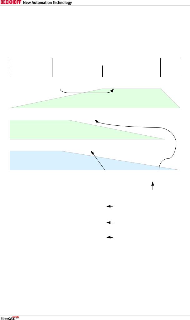
Figure 2 shows how an Ethernet frame containing EtherCAT data is assembled.
|
|
|
|
|
|
|
|
|
|
|
|
|
|
|
|
|
|
64-1522 Byte |
|
|
|
|
|
|||
|
|
|
|
|
|
|
|
|
|
|
|
|
|
|
|
|
|
|
|
|
|
|
|
|||
|
Ethernet frame |
|
|
|
|
|
|
|
|
|
|
|
|
Ethernet Header |
|
|
|
|
Ethernet Data |
FCS |
||||||
|
|
|
|
|
|
|
|
|
|
|
|
|
48 bit |
|
48 bit |
|
16 bit |
|
|
|
|
46-1500 Byte |
|
32 bit |
||
|
Basic EtherCAT frame |
|
|
|
|
|
|
|
Destination |
Source |
|
EtherType |
|
|
|
|
EtherCAT Data |
FCS |
||||||||
|
|
|
|
|
|
|
|
|
0x88A4 |
|
|
|
|
|||||||||||||
|
|
|
|
|
|
|
|
|
|
|
|
|
|
|
|
|
|
|
|
|
|
|
|
|
|
|
|
|
|
|
|
|
|
|
|
|
|
|
|
|
|
|
|
|
|
|
|
16 bit |
|
44-1498 Byte |
|
|
|
|
Basic EtherCAT frame |
|
|
|
|
|
|
|
Destination |
Source |
|
EtherType |
EtherCAT Header |
Datagrams |
FCS |
|||||||||||
|
|
|
|
|
|
|
|
|
0x88A4 |
|||||||||||||||||
|
|
|
|
|
|
|
|
|
|
|
|
|
|
|
|
|
|
|
|
|
|
|
|
|
|
|
|
|
|
|
|
|
|
|
|
|
|
|
|
|
|
32 bit |
|
|
|
|
|
|
|
44-1498 Byte |
|
|
|
|
Basic EtherCAT frame with |
|
|
Destination |
|
Source |
|
VLAN Tag |
EtherType |
EtherCAT Header |
Datagrams |
FCS |
||||||||||||||
|
VLAN tag |
|
|
|
|
|
|
|
0x88A4 |
|||||||||||||||||
|
|
|
|
|
|
|
|
|
|
|
|
|
|
|
|
|
|
|
|
|
|
|
|
|||
|
|
|
|
|
|
|
|
|
|
|
|
|
|
|
160 bit |
|
64 bit |
|
|
|
|
|
16-1478 Byte |
|
|
|
|
EtherCAT in |
|
Destination |
Source |
|
EtherType |
IP Header |
|
UDP Header |
EtherCAT Header |
Datagrams |
FCS |
||||||||||||||
|
UDP/IP frame |
|
|
0x0800 |
dest. port 0x88A4 |
|||||||||||||||||||||
|
|
|
|
|
|
|
|
|
|
|
|
|
|
|
|
|
|
|
|
|||||||
|
|
|
|
|
|
|
|
|
|
|
|
|
|
|
|
|
|
|
|
|
|
|
16-1478 Byte |
|
|
|
|
Destination |
|
|
Source |
VLAN Tag |
EtherType |
IP Header |
|
UDP Header |
EtherCAT Header |
Datagrams |
FCS |
||||||||||||||
|
|
|
0x0800 |
dest. port 0x88A4 |
||||||||||||||||||||||
|
|
|
|
|
|
|
|
|
|
|
|
|
|
|
|
|
|
|
|
|
|
|||||
|
EtherCAT in UDP/IP frame |
|
|
|
|
|
|
|
|
|
|
|
|
|
|
|
|
|
|
|
|
|
||||
|
with VLAN tag |
|
|
|
|
|
|
|
|
|
|
|
|
|
|
|
|
|
|
|
|
|
|
|
|
|
|
|
|
|
|
|
|
|
|
|
|
|
|
|
|
|
|
|
11 bit |
1 bit |
4 bit |
|
|
|
|
||
|
|
|
|
|
|
|
|
|
|
|
|
|
|
|
|
|
|
Length |
Res. |
Type |
|
|
|
|
||
|
|
|
|
|
|
|
|
|
|
|
|
|
|
|
|
|
|
EtherCAT frame header |
|
|
|
|
||||
|
|
|
|
|
|
|
|
|
|
Figure 2: Ethernet Frame with EtherCAT Data |
|
|
|
|
|
|||||||||||
|
|
|
|
|
|
|
|
|
|
|
|
Table 2: EtherCAT Frame Header |
|
|
|
|
|
|
||||||||
|
|
|
|
|
|
|
|
|
|
|
|
|
|
|
|
|
|
|
|
|||||||
|
Field |
|
|
|
Data Type |
|
|
Value/Description |
|
|
|
|
|
|
|
|
|
|
|
|||||||
|
|
|
|
|
|
|
|
|
|
|
|
|
||||||||||||||
|
Length |
|
|
|
11 bit |
|
|
|
Length of the EtherCAT datagrams (excl. FCS) |
|
|
|
|
|||||||||||||
|
|
|
|
|
|
|
|
|
|
|
|
|
|
|
|
|
|
|
|
|
|
|||||
|
Reserved |
|
|
|
1 bit |
|
|
|
Reserved, 0 |
|
|
|
|
|
|
|
|
|
|
|
|
|
||||
|
|
|
|
|
|
|
|
|
||||||||||||||||||
|
Type |
|
|
|
4 bit |
|
|
|
Protocol type. Only EtherCAT commands (Type = 0x1) are supported |
|
||||||||||||||||
|
|
|
|
|
|
|
|
|
by ESCs. |
|
|
|
|
|
|
|
|
|
|
|
|
|
||||
|
|
|
|
|
|
|
|
|
|
|
|
|
|
|
|
|
|
|
|
|
|
|
|
|
|
|
NOTE: The EtherCAT header length field is ignored by ESCs, they rely on the datagram length fields.
1 ESCs have to be configured to forward non-EtherCAT frames via DL Control register 0x0100[0].
I-4 |
Slave Controller – Technology |
EtherCAT Protocol
2.2EtherCAT Datagram
Figure 3 shows the structure of an EtherCAT frame.
|
* add 1-32 padding bytes if Ethernet frame is shorter than |
||||
|
|
64 Bytes (Ethernet Header+Ethernet Data+FCS) |
|||
Ethernet header |
|
|
Ethernet Data |
FCS |
|
|
EtherCAT header |
|
|
||
14 Byte |
11 bit |
1 bit |
4 bit |
44*-1498 Byte |
4 Byte |
Ethernet header |
Length |
Res. |
Type |
1...n Datagrams |
FCS |
1 |
st |
EtherCAT Datagram |
2 |
nd |
... |
... |
n |
th |
EtherCAT Datagram |
|
|
|
|
10 Byte |
|
0-1486 Byte |
|
|
2 Byte |
|
|
|
Datagram Header |
Data |
|
Working Counter |
|
|
||||
|
|
(WKC) |
|
|
|||||
|
|
|
|
|
|
|
|
||
8 Bit |
8 Bit |
32 Bit |
11 Bit |
3 Bit |
1 |
1 |
16 Bit |
||
Cmd |
Idx |
Address |
Len |
R |
C |
M |
|
IRQ |
|
0 |
8 |
16 |
|
48 |
59 |
62 |
63 |
64 |
79 |
|
|
16 Bit |
16 Bit |
|
More EtherCAT Datagrams |
||||
|
|
|
|
|
|
|
|
||
|
|
Position |
Offset |
Position Addressing |
|
|
|||
|
|
Address |
Offset |
Node Addressing |
|
|
|
||
|
|
Logical Address |
Logical Addressing |
|
|
||||
|
|
Figure 3: EtherCAT Datagram |
|
|
|
|
|
||
Slave Controller – Technology |
I-5 |

EtherCAT Protocol
|
|
|
|
|
|
|
|
|
Table 3: EtherCAT Datagram |
||
|
|
|
|
|
|
|
|
|
|
|
|
|
Field |
|
|
|
Data Type |
|
|
|
Value/Description |
|
|
|
|
|
|
|
|
|
|
||||
|
Cmd |
|
|
|
BYTE |
|
|
|
EtherCAT Command Type (see 2.5) |
|
|
|
|
|
|
|
|
|
|
||||
|
Idx |
|
|
|
BYTE |
|
|
|
The index is a numeric identifier used by the master for |
|
|
|
|
|
|
|
|
|
|
|
identification of duplicates/lost datagrams. It shall not be changed |
|
|
|
|
|
|
|
|
|
|
|
by EtherCAT slaves |
|
|
|
|
|
|
|
|
|
|
||||
|
Address |
|
|
|
BYTE[4] |
|
|
|
Address (Auto Increment, Configured Station Address, or Logical |
|
|
|
|
|
|
|
|
|
|
|
Address, see 2.3) |
|
|
|
|
|
|
|
|
|
|
||||
|
Len |
|
|
|
11 bit |
|
|
|
Length of the following data within this datagram |
|
|
|
|
|
|
|
|
|
|
||||
|
R |
|
|
|
3 bit |
|
|
|
Reserved, 0 |
|
|
|
|
|
|
|
|
|
|
||||
|
C |
|
|
|
1 bit |
|
|
|
Circulating frame (see 3.5): |
|
|
|
|
|
|
|
|
|
|
|
0: |
Frame is not circulating |
|
|
|
|
|
|
|
|
|
|
1: |
Frame has circulated once |
|
|
|
|
|
|
|
|
|
||||
|
M |
|
|
|
1 bit |
|
|
|
More EtherCAT datagrams |
|
|
|
|
|
|
|
|
|
|
|
0: |
Last EtherCAT datagram |
|
|
|
|
|
|
|
|
|
|
1: |
More EtherCAT datagrams will follow |
|
|
|
|
|
|
|
|
|
||||
|
IRQ |
|
|
|
WORD |
|
|
|
EtherCAT Event Request registers of all slaves combined with a |
|
|
|
|
|
|
|
|
|
|
|
logical OR |
|
|
|
|
|
|
|
|
|
|
||||
|
Data |
|
|
|
BYTE[n] |
|
|
|
Read/Write Data |
|
|
|
|
|
|
|
|
|
|
||||
|
WKC |
|
|
|
WORD |
|
|
|
Working Counter (see 2.4) |
|
|
|
|
|
|
|
|
|
|
|
|
|
|
2.3EtherCAT Addressing Modes
Two addressing modes of EtherCAT devices are supported within one segment: device addressing and logical addressing. Three device addressing modes are available: auto increment addressing, configured station address, and broadcast. EtherCAT devices can have up to two configured station addresses, one is assigned by the master (Configured Station Address), the other one is stored in the SII EEPROM and can be changed by the slave application (Configured Station Alias address). The EEPROM setting for the Configured Station Alias address is only taken over at the first EEPROM loading after power-on or reset.
|
|
|
|
|
|
Table 4: EtherCAT Addressing Modes |
||||||||
|
|
|
|
|
|
|
|
|
|
|
|
|
|
|
|
Mode |
|
|
|
Field |
|
|
|
Data Type |
|
|
|
Value/Description |
|
|
|
|
|
|
|
|
|
|
|
|
|
|||
|
Auto Increment |
|
|
|
Position |
|
|
|
WORD |
|
|
|
Each slave increments Position. |
|
|
Address |
|
|
|
|
|
|
|
|
|
|
|
Slave is addressed if Position = 0. |
|
|
|
|
|
|
|
|
|
|
|
|
|
|
||
|
|
|
|
|
Offset |
|
|
|
WORD |
|
|
|
Local register or memory address of the ESC |
|
|
|
|
|
|
|
|
|
|
|
|
|
|||
|
Configured |
|
|
|
Address |
|
|
|
WORD |
|
|
|
Slave is addressed if Address matches |
|
|
Station Address |
|
|
|
|
|
|
|
|
|
|
|
Configured Station Address or Configured |
|
|
|
|
|
|
|
|
|
|
|
|
|
|
Station Alias (if enabled). |
|
|
|
|
|
|
|
|
|
|
|
|
|
|
||
|
|
|
|
|
Offset |
|
|
|
WORD |
|
|
|
Local register or memory address of the ESC |
|
|
|
|
|
|
|
|
|
|
|
|
|
|||
|
Broadcast |
|
|
|
Position |
|
|
|
WORD |
|
|
|
Each slave increments Position (not used for |
|
|
|
|
|
|
|
|
|
|
|
|
|
|
addressing) |
|
|
|
|
|
|
|
|
|
|
|
|
|
|
||
|
|
|
|
|
Offset |
|
|
|
WORD |
|
|
|
Local register or memory address of the ESC |
|
|
|
|
|
|
|
|
|
|
|
|
|
|||
|
Logical Address |
|
|
|
Address |
|
|
|
DWORD |
|
|
|
Logical Address (configured by FMMUs) |
|
|
|
|
|
|
|
|
|
|
|
|
|
|
Slave is addressed if FMMU configuration |
|
|
|
|
|
|
|
|
|
|
|
|
|
|
matches Address. |
|
I-6 |
Slave Controller – Technology |

EtherCAT Protocol
2.3.1Device Addressing
The device can be addressed via Device Position Address (Auto Increment address), by Node Address (Configured Station Address/Configured Station Alias), or by a Broadcast.
Position Address / Auto Increment Address:
The datagram holds the position address of the addressed slave as a negative value. Each slave increments the address. The slave which reads the address equal zero is addressed and will execute the appropriate command at receive.
Position Addressing should only be used during start-up of the EtherCAT system to scan the fieldbus and later only occasionally to detect newly attached slaves. Using Position addressing is problematic if loops are closed temporarily due to hot connecting or link problems. Position addresses are shifted in this case, and e.g., a mapping of error register values to devices becomes impossible, thus the faulty link cannot be localized.
Node Address / Configured Station Address and Configured Station Alias:
The configured Station Address is assigned by the master during start up and cannot be changed by the EtherCAT slave. The Configured Station Alias address is stored in the SII EEPROM and can be changed by the EtherCAT slave. The Configured Station Alias has to be enabled by the master. The appropriate command action will be executed if Node Address matches with either Configured Station Address or Configured Station Alias.
Node addressing is typically used for register access to individual and already identified devices.
Broadcast:
Each EtherCAT slave is addressed.
Broadcast addressing is used e.g. for initialization of all slaves and for checking the status of all slaves if they are expected to be identical.
Each slave device has a 16 bit local address space (address range 0x0000:0x0FFF is dedicated for EtherCAT registers, address range 0x1000:0xFFFF is used as process memory) which is addressed via the Offset field of the EtherCAT datagram. The process memory address space is used for application communication (e.g. mailbox access).
2.3.2Logical Addressing
All devices read from and write to the same logical 4 Gbyte address space (32 bit address field within the EtherCAT datagram). A slave uses a mapping unit (FMMU, Fieldbus Memory Management Unit) to map data from the logical process data image to its local address space. During start up the master configures the FMMUs of each slave. The slave knows which parts of the logical process data image have to be mapped to which local address space using the configuration information of the FMMUs.
Logical Addressing supports bit wise mapping. Logical Addressing is a powerful mechanism to reduce the overhead of process data communication, thus it is typically used for accessing process data.
Slave Controller – Technology |
I-7 |

EtherCAT Protocol
2.4Working Counter
Every EtherCAT datagram ends with a 16 Bit Working Counter (WKC). The Working Counter counts the number of devices that were successfully addressed by this EtherCAT datagram. Successfully means that the ESC is addressed and the addressed memory is accessible (e.g., protected SyncManager buffer). EtherCAT Slave Controllers increment the Working Counter in hardware. Each datagram should have an expected Working Counter value calculated by the master. The master can check the valid processing of EtherCAT datagrams by comparing the Working Counter with the expected value.
The Working Counter is increased if at least one byte/one bit of the whole multi-byte datagram was successfully read and/or written. For a multi-byte datagram, you cannot tell from the Working Counter value if all or only one byte was successfully read and/or written. This allows reading separated register areas using a single datagram by ignoring unused bytes.
The Read-Multiple-Write commands ARMW and FRMW are either treated like a read command or like a write command, depending on the address match.
|
Table 5: Working Counter Increment |
|
|
|
|
|||||
|
|
|
|
|
|
|
|
|
|
|
|
Command |
|
|
|
Data Type |
|
|
|
Increment |
|
|
|
|
|
|
|
|
|
|||
|
Read command |
|
|
|
No success |
|
|
|
no change |
|
|
|
|
|
|
|
|
|
|||
|
|
|
|
|
Successful read |
|
|
|
+1 |
|
|
|
|
|
|
|
|
|
|||
|
Write command |
|
|
|
No success |
|
|
|
no change |
|
|
|
|
|
|
|
|
|
|||
|
|
|
|
|
Successful write |
|
|
|
+1 |
|
|
|
|
|
|
|
|
|
|||
|
ReadWrite command |
|
|
|
No success |
|
|
|
no change |
|
|
|
|
|
|
|
|
|
|||
|
|
|
|
|
Successful read |
|
|
|
+1 |
|
|
|
|
|
|
|
|
|
|||
|
|
|
|
|
Successful write |
|
|
|
+2 |
|
|
|
|
|
|
|
|
|
|||
|
|
|
|
|
Successful read and write |
|
|
|
+3 |
|
|
|
|
|
|
|
|
|
|
|
|
I-8 |
Slave Controller – Technology |

EtherCAT Protocol
2.5EtherCAT Command Types
All supported EtherCAT Command types are listed in Table 6. For ReadWrite operations, the Read operation is performed before the Write operation.
Slave Controller – Technology |
I-9 |
EtherCAT Protocol
CMD |
Abbr. |
0 |
NOP |
1 |
APRD |
2 |
APWR |
3 |
APRW |
4 |
FPRD |
5 |
FPWR |
6 |
FPRW |
7 |
BRD |
8 |
BWR |
9 |
BRW |
10 |
LRD |
11 |
LWR |
12 |
LRW |
13 |
ARMW |
14 |
FRMW |
15-255 |
|
Table 6: EtherCAT Command Types
|
Name |
|
|
|
Description |
|
|
|
|
|
|
||
|
|
|
|
|
||
|
No Operation |
|
|
|
Slave ignores command |
|
|
|
|
|
|
||
|
Auto Increment Read |
|
|
|
Slave increments address. Slave puts read data |
|
|
|
|
|
|
into the EtherCAT datagram if received address is |
|
|
|
|
|
|
zero. |
|
|
|
|
|
|
||
|
Auto Increment Write |
|
|
|
Slave increments address. Slave writes data into |
|
|
|
|
|
|
memory location if received address is zero. |
|
|
|
|
|
|
|
|
Auto Increment Read Write
Configured Address Read
Slave increments address. Slave puts read data into the EtherCAT datagram and writes the data into the same memory location if received address is zero.
Slave puts read data into the EtherCAT datagram if address matches with one of its configured addresses
Configured Address Write
Configured Address Read
Write
Broadcast Read
Broadcast Write
Broadcast Read Write
Logical Memory Read
Logical Memory Write
Logical Memory Read Write
Auto Increment Read
Multiple Write
Configured Read Multiple
Write
reserved
Slave writes data into memory location if address matches with one of its configured addresses
Slave puts read data into the EtherCAT datagram and writes data into the same memory location if address matches with one of its configured addresses
All slaves put logical OR of data of the memory area and data of the EtherCAT datagram into the EtherCAT datagram. All slaves increment position field.
All slaves write data into memory location. All slaves increment position field.
All slaves put logical OR of data of the memory area and data of the EtherCAT datagram into the EtherCAT datagram, and write data into memory location. BRW is typically not used. All slaves increment position field.
Slave puts read data into the EtherCAT datagram if received address matches with one of the configured FMMU areas for reading.
Slaves writes data to into memory location if received address matches with one of the configured FMMU areas for writing.
Slave puts read data into the EtherCAT datagram if received address matches with one of the configured FMMU areas for reading. Slaves writes data to into memory location if received address matches with one of the configured FMMU areas for writing.
Slave increments address. Slave puts read data into the EtherCAT datagram if received address is zero, otherwise slave writes the data into memory location.
Slave puts read data into the EtherCAT datagram if address matches with one of its configured addresses, otherwise slave writes the data into memory location.
I-10 |
Slave Controller – Technology |
Loading...