


CB3063
Manual
rev. 0.3
Beckhoff Automation GmbH & Co. KG |
phone: |
+49 (0) 52 46/963-0 |
Eiserstr. 5 |
fax: |
+49 (0) 52 46/963-198 |
33415 Verl |
email: |
info@beckhoff.de |
Germany |
web: |
www.beckhoff.de |

|
|
|
|
Contents |
|
|
|||
Contents |
|
|||
0 |
Document History................................................................................................................................. |
6 |
||
1 |
Introduction .......................................................................................................................................... |
7 |
||
|
1.1 |
Notes on the Documentation ........................................................................................................ |
7 |
|
|
1.1.1 |
Liability Conditions ................................................................................................................ |
7 |
|
|
1.1.2 |
Copyright............................................................................................................................... |
7 |
|
|
1.2 |
Safety Instructions ........................................................................................................................ |
8 |
|
|
1.2.1 |
Disclaimer ............................................................................................................................. |
8 |
|
|
1.2.2 |
Description of Safety Symbols.............................................................................................. |
9 |
|
|
1.3 |
Essential Safety Measures ......................................................................................................... |
10 |
|
|
1.3.1 |
Operator's Obligation to Exercise Diligence ....................................................................... |
10 |
|
|
1.3.2 |
National Regulations Depending on the Machine Type ..................................................... |
10 |
|
|
1.3.3 |
Operator Requirements ...................................................................................................... |
10 |
|
|
1.4 |
Functional Range........................................................................................................................ |
11 |
|
2 |
Overview |
............................................................................................................................................ |
12 |
|
|
2.1 |
Features...................................................................................................................................... |
12 |
|
|
2.2 |
Specifications and Documents ................................................................................................... |
13 |
|
3 |
Detailed Description ........................................................................................................................... |
14 |
||
|
3.1 |
Power Supply / UPS ................................................................................................................... |
14 |
|
|
3.2 |
CPU |
............................................................................................................................................ |
14 |
|
3.3 |
SUPS .......................................................................................................................................... |
14 |
|
|
3.4 |
Memory ....................................................................................................................................... |
14 |
|
4 |
Connectors......................................................................................................................................... |
15 |
||
|
4.1 |
Connector Map ........................................................................................................................... |
16 |
|
|
4.2 |
Power Supply.............................................................................................................................. |
17 |
|
|
4.3 |
Power Connector ........................................................................................................................ |
18 |
|
|
4.4 |
Power Connector ........................................................................................................................ |
19 |
|
|
4.5 |
SUSV .......................................................................................................................................... |
20 |
|
|
4.6 |
System ........................................................................................................................................ |
21 |
|
|
4.7 |
Memory ....................................................................................................................................... |
22 |
|
|
4.8 |
VGA/DVI ..................................................................................................................................... |
25 |
|
|
4.9 |
DVI/HDMI/DisplayPort ................................................................................................................ |
27 |
|
|
4.10 |
USB 3-6 ...................................................................................................................................... |
29 |
|
|
4.11 |
USB 2, 7-9 .................................................................................................................................. |
30 |
|
|
4.12 |
LAN ............................................................................................................................................. |
|
31 |
|
4.13 |
SATA Interfaces.......................................................................................................................... |
33 |
|
|
4.14 |
Serial Interface COM 1 ............................................................................................................... |
34 |
|
|
4.15 |
PCI-Express................................................................................................................................ |
35 |
|
|
4.16 |
GPIO ........................................................................................................................................... |
37 |
|
|
4.17 |
Fan Connectors .......................................................................................................................... |
38 |
|
5 |
BIOS Settings..................................................................................................................................... |
39 |
||
|
5.1 |
General Remarks........................................................................................................................ |
39 |
|
|
5.2 |
Main |
............................................................................................................................................ |
40 |
|
5.3 |
Advanced .................................................................................................................................... |
41 |
|
|
5.3.1 |
ACPI Settings...................................................................................................................... |
43 |
|
|
5.3.2 |
H/W Monitor ........................................................................................................................ |
44 |
|
|
5.3.3 |
Serial Port Console Redirection.......................................................................................... |
46 |
|
|
|
|||
Beckhoff New Automation Technology CB3063 |
page 3 |
|||

Contents
|
5.3.4 |
CPU Configuration .............................................................................................................. |
49 |
|
|
5.3.5 |
PPM Configuration .............................................................................................................. |
53 |
|
|
5.3.6 |
SATA Configuration ............................................................................................................ |
54 |
|
|
5.3.7 |
Miscellaneous Configuration ............................................................................................... |
55 |
|
|
5.3.8 |
LPSS & SCC Configuration ................................................................................................ |
56 |
|
|
5.3.9 |
Network Stack ..................................................................................................................... |
58 |
|
|
5.3.10 |
Power Controller Options .................................................................................................... |
59 |
|
|
5.3.11 |
CSM Configuration ............................................................................................................. |
61 |
|
|
5.3.12 |
SDIO Configuration ............................................................................................................. |
62 |
|
|
5.3.13 |
USB Configuration .............................................................................................................. |
63 |
|
|
5.3.14 |
Security Configuration ........................................................................................................ |
64 |
|
|
5.3.15 |
SIO Configuration ............................................................................................................... |
65 |
|
|
5.4 |
Chipset........................................................................................................................................ |
68 |
|
|
5.4.1 |
North Bridge ........................................................................................................................ |
69 |
|
|
5.4.2 |
South Bridge ....................................................................................................................... |
73 |
|
|
5.5 |
Security ....................................................................................................................................... |
77 |
|
|
5.5.1 |
Secure Boot menu .............................................................................................................. |
78 |
|
|
5.6 |
Boot |
............................................................................................................................................. |
81 |
|
5.7 |
Save .................................................................................................................................& Exit |
82 |
|
|
5.8 |
BIOS ..............................................................................................................................-Update |
83 |
|
6 |
Mechanical .........................................................................................................................Drawings |
84 |
||
|
6.1 |
PCB: .................................................................................................................Mounting Holes |
84 |
|
|
6.2 |
PCB: ..............................................................................................................Pin 1 Dimensions |
85 |
|
|
6.3 |
PCB: .........................................................................................................................Die Center |
86 |
|
|
6.4 |
PCB: .............................................................................................................................Outlines |
87 |
|
7 |
Technical ...................................................................................................................................Data |
88 |
||
|
7.1 |
Electrical .............................................................................................................................Data |
88 |
|
|
7.2 |
Environmental ...........................................................................................................Conditions |
88 |
|
|
7.3 |
Thermal ...............................................................................................................Specifications |
89 |
|
I |
Annex: Post ............................................................................................................................-Codes |
91 |
||
II |
Annex: Resources.............................................................................................................................. |
92 |
||
|
IO Range ................................................................................................................................................ |
|
92 |
|
|
Memory Range ....................................................................................................................................... |
92 |
||
|
Interrupt .................................................................................................................................................. |
|
92 |
|
|
PCI Devices............................................................................................................................................ |
93 |
||
|
SMB Devices .......................................................................................................................................... |
93 |
||
page 4 |
Beckhoff New Automation Technology CB3063 |

Notes on the Documentation |
Chapter: Document History |
|
|
Beckhoff New Automation Technology CB3063 |
page 5 |

Chapter: Document History Notes on the Documentation
0 |
Document History |
|
|
|
|
|
|
|
Version |
|
Changes |
|
|
|
|
0.1 |
|
first pre-release |
|
0.2 |
|
removed audio, updated LAN pinout |
|
0.3 |
|
corrected block diagram |
|
 NOTE
NOTE
All company names, brand names, and product names referred to in this manual are registered or unregistered trademarks of their respective holders and are, as such, protected by national and international law.
page 6 |
Beckhoff New Automation Technology CB3063 |

Notes on the Documentation |
Chapter: Introduction |
|
|
1 Introduction
1.1 Notes on the Documentation
This description is only intended for the use of trained specialists in control and automation engineering who are familiar with the applicable national standards. It is essential that the following notes and explanations are followed when installing and commissioning these components.
1.1.1Liability Conditions
The responsible staff must ensure that the application or use of the products described satisfy all the requirements for safety, including all the relevant laws, regulations, guidelines and standards.
The documentation has been prepared with care. The products described are, however, constantly under development. For that reason the documentation is not in every case checked for consistency with performance data, standards or other characteristics. None of the statements of this manual represents a guarantee (Garantie) in the meaning of § 443 BGB of the German Civil Code or a statement about the contractually expected fitness for a particular purpose in the meaning of § 434 par. 1 sentence 1 BGB. In the event that it contains technical or editorial errors, we retain the right to make alterations at any time and without warning. No claims for the modification of products that have already been supplied may be made on the basis of the data, diagrams and descriptions in this documentation.
1.1.2Copyright
© This documentation is copyrighted. Any reproduction or third party use of this publication, whether in whole or in part, without the written permission of Beckhoff Automation GmbH & Co. KG, is forbidden.
Beckhoff New Automation Technology CB3063 |
page 7 |

Chapter: Introduction |
Safety Instructions |
|
|
1.2 Safety Instructions
Please consider the following safety instructions and descriptions. Product specific safety instructions are to be found on the following pages or in the areas mounting, wiring, commissioning etc.
1.2.1Disclaimer
All the components are supplied in particular hardware and software configurations appropriate for the application. Modifications to hardware or software configurations other than those described in the documentation are not permitted, and nullify the liability of Beckhoff Automation GmbH & Co. KG.
page 8 |
Beckhoff New Automation Technology CB3063 |

Safety Instructions |
Chapter: Introduction |
|
|
1.2.2Description of Safety Symbols
The following safety symbols are used in this documentation. They are intended to alert the reader to the associated safety instructions.
 ACUTE RISK OF INJURY!
If you do not adhere to the safety advise next to this symbol, there is immediate danger to life and health of individuals!
 RISK OF INJURY!
If you do not adhere to the safety advise next to this symbol, there is danger to life and health of individuals!
 HAZARD TO INDIVIDUALS, ENVIRONMENT, DEVICES, OR DATA!
If you do not adhere to the safety advise next to this symbol, there is obvious hazard to individuals, to environment, to materials, or to data.
 NOTE OR POINTER
This symbol indicates information that contributes to better understanding.
Beckhoff New Automation Technology CB3063 |
page 9 |

Chapter: Introduction |
Essential Safety Measures |
|
|
1.3 Essential Safety Measures
1.3.1Operator's Obligation to Exercise Diligence
The operator must ensure that
o the product is only used for its intended purpose
o the product is only operated in sound condition and in working order
o the instruction manual is in good condition and complete, and always available for reference at the location where the products are used
o the product is only used by suitably qualified and authorised personnel
othe personnel is instructed regularly about relevant occupational safety and environmental protection aspects
othe operating personnel is familiar with the operating manual and in particular the safety notes contained herein
1.3.2National Regulations Depending on the Machine Type
Depending on the type of machine and plant in which the product is used, national regulations governing the controllers of such machines will apply, and must be observed by the operator. These regulations cover, amongst other things, the intervals between inspections of the controller. The operator must initiate such inspections in good time.
1.3.3Operator Requirements
o Read the operating instructions
All users of the product must have read the operating instructions for the system they work with.
o System know-how
All users must be familiar with all accessible functions of the product.
page 10 |
Beckhoff New Automation Technology CB3063 |
Functional Range |
Chapter: Introduction |
|
|
1.4 Functional Range
 NOTE
NOTE
The descriptions contained in the present documentation represent a detailed and extensive product description. As far as the described motherboard was acquired as an integral component of an Industrial PC from Beckhoff Automation GmbH & Co. KG, this product description shall be applied only in limited scope. Only the contractually agreed specifications of the corresponding Industrial PC from Beckhoff Automation GmbH & Co. KG shall be relevant. Due to several models of Industrial PCs, variations in the component placement of the motherboards are possible. Support and service benefits for the built-in motherboard will be rendered by Beckhoff Automation GmbH & Co. KG exclusively as specified in the product description (inclusive operation system) of the particular Industrial PC.
Beckhoff New Automation Technology CB3063 |
page 11 |
Chapter: Overview |
Features |
|
|
2 Overview
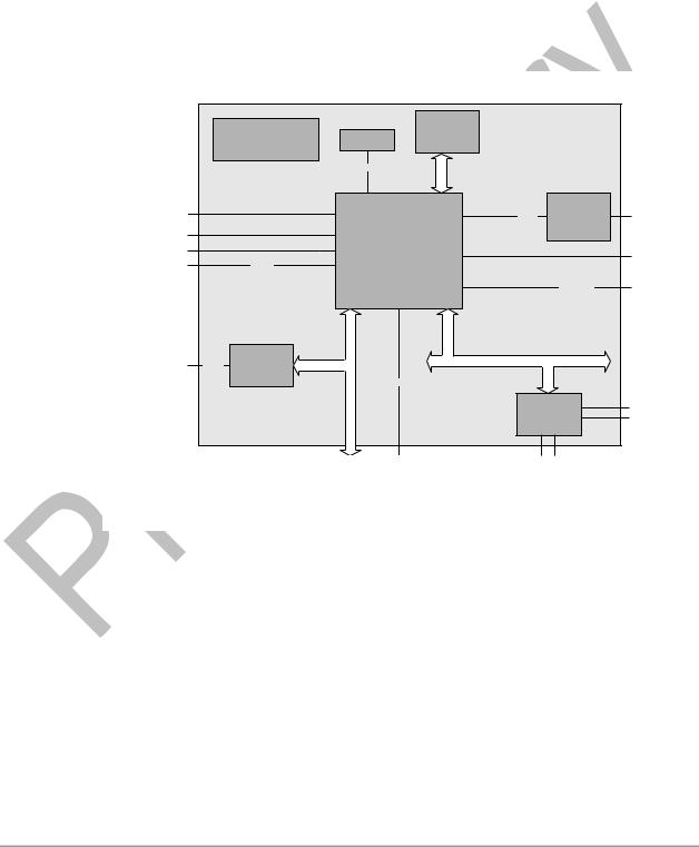
2.1 Features
The CB3063 is a highly complex 3,5-inch board which incorporates complete motherboard functionality. It's based on a System-On-Chip (SoC) of Intel®'s Atom E3800 product family. Modern low voltage DDR3L technology provides top-notch memory performance, accomodating up to 8 GByte of RAM (DDR3L-1333) via SO-DIMM204. It also provides a PCI-Express bus (via a 2x40 pin custom connector, configurable as one 1x) and additional peripheral devices such as a serial interface, three Gigabit Ethernet interfaces (LAN), two SATA channels (offering up to 3Gb/s), nine USB channels, and two DVI/HDMI connectors with CRT available through DVI-I, and DisplayPort available on a 30pin I-PEX connector. Input voltage is 24V, which is galvanically isolated from the voltages generated on the board.
|
|
|
|
1x |
|
|
|
|
|
Power VCCCore; |
|
SoDIMM204 |
|
|
|
|
|
|
DDR3L- |
|
|
|
|
|
|
DDRVTT; GFXVCC; |
BIOS |
|
|
|
|
|
|
1333 |
|
|
|
||
|
1.05V; 1.5V; 1.8V; 3.3V |
|
|
|
|
||
|
|
|
|
|
|
||
|
|
|
SPI |
MEMORY |
|
|
|
|
|
|
|
|
|
|
|
DVI/HDMI/DP |
|
|
|
|
|
NXP® |
8x GPIO |
(I-PEX) |
|
|
|
|
SMBus |
||
|
|
|
|
PCA9535 |
|||
|
|
|
|
|
|
||
|
|
|
|
|
|
|
|
DVI/HDMI |
|
|
Intel® Atom™ |
|
|
|
|
CRT |
|
|
|
|
|
||
|
|
E3840, E3823 |
|
|
SMBus |
||
USB2-9 |
|
USB 2.0 |
|
|
|||
|
|
|
|
|
|
||
|
|
|
|
|
|
1.5GB/3.0GB |
SATA1-2 |
LAN1-3 |
10/100/ |
Intel® |
|
|
LPC |
|
|
1000 |
i210 |
|
|
|
|
|
|
|
|
|
|
|
|
||
|
|
|
|
|
|
|
|
|
|
|
|
USB 3.0 |
|
|
|
|
|
|
|
|
SMSC® |
KB |
|
|
|
|
|
|
SCH3114 |
MS |
|
|
|
PCIe x1 |
|
USB1 (I-PEX) |
FAN 1-3 |
COM1 |
|
|
|
1 x |
|
|
|
|
|
o Single-Chip-Processor Intel® Atom™ E3840, E3823
o SO-DIMM204 socket for one DDR3L-1333 module of up to 8 GByte o PCI-Express bus (x1) via 2x40pin custom connector
o Serial interface COM1
o Three LAN interfaces Ethernet 10/100/1000 (Base-T) o Two SATA channels (up to 3Gb/s transfer rate)
o PS2 keyboard / mouse interface
o Nine USB 2.0 interfaces (4x external, 4x internal, 1x on I-PEX connector) o BIOS AMI® Aptio
o CRT connection
o Two DVI/HDMI connectors (1x DVI-I, 1x I-PEX with DisplayPort capability) o 8x GPIO
o RTC with external CMOS battery o 24V supply, galvanically isolated o Format: 102 mm x 147 mm
page 12 |
Beckhoff New Automation Technology CB3063 |

Specifications and Documents |
Chapter: Overview |
|
|
2.2 Specifications and Documents
In making this manual and for further reading of technical documentation, the following documents, specifications and web-pages were used and are recommended.
oPCI specification Version 2.3 bzw. 3.0 www.pcisig.com
PCI Express® Base specification Version 2.0
www.pcisig.com
ACPI specification Version 3.0 www.acpi.info
ATA/ATAPI specification Version 7 Rev. 1 www.t13.org
USB spezifications www.usb.org
SM-Bus specification Version 2.0 www.smbus.org
Intel® Chip Description
Intel® Atom™ Processor E3800 Product Family datasheet www.intel.com
Intel® Chip Description i210 Datasheet www.intel.com
SMSC® Chip Description SCH3114 Datasheet www.smsc.com
(NDA required)
American Megatrends®
Aptio™ Text Setup Environment (TSE) User Manual www.ami.com
American Megatrends®
Aptio™ 4.x Status Codes www.ami.com
Beckhoff New Automation Technology CB3063 |
page 13 |

Chapter: Detailed Description |
Power Supply / UPS |
|
|
3 Detailed Description
3.1 Power Supply / UPS
The CB3063 needs an external power supply of 24V (will tolerate 20V-30V). This input is galvanically isolated from the board's internal circuitry. It is also used for charging any UPS device that may be present. This UPS device is either capacitor-based or connected externally as a Pb-battery pack. With a UPS installed and charged, the module can stay operational even when a power failure occurs. A capacitor-based UPS can keep the board alive only for a few seconds while a Pb-battery typically allows for several minutes of continued operation. The exact amount of time is hard to predict as it also depends on factors such as the UPS' charge level at the time of the power failure, CPU/chipset power consumption etc. Generally, a Pb-battery needs a much longer time to reach full charge level compared to a capacitor-based UPS.
3.2 CPU
The motherboard employs an Intel® Atom™ processor of the E3800 family, which is a system-on-chip (SoC) being optimized for low power consumption while at the same time providing state-of-the-art computing performance.
The processors include a second level cache of 512 KByte. They also offer many features known from the desktop range such as MMX2, serial number, loadable microcode etc.
The Atom™ CPU operates in an extended range of thermal conditions and therefore is capable for use in industrial systems.
3.3 SUPS
Optionally the CB3063 can be equipped with a plug-in SUPS, which can keep the board alive for a few seconds in case of power failure or voltage fluctuation. The exact amount of time is hard to predict as it also depends on factors such as the SUPS' capacitors and the boards' power consumption etc. The capacitors size is only limited by the required space.
3.4 Memory
There is one conventional SO-DIMM204 socket available to equip the board with memory. For technical and mechanical reasons it is possible that particular memory modules cannot be employed. Please ask your sales representative for recommended memory modules.
With currently available SO-DIMM204 modules a memory extension up to 8 GByte is possible (DDR3L-1333).
 NOTICE
For optimal driver compatibility we recommend the use of a Microsoft® Windows® 8 operating system.
page 14 |
Beckhoff New Automation Technology CB3063 |

Memory |
Chapter: Connectors |
|
|
4 Connectors
This section describes all the connectors found on the CB3063.
 NOTICE
For most interfaces, the cables must meet certain requirements. For instance, USB 2.0 requires twisted and shielded cables to reliably maintain full speed data rates. Restrictions on maximum cable length are also in place for many high speed interfaces and for power supply. Please refer to the respective specifications and use suitable cables at all times.
Beckhoff New Automation Technology CB3063 |
page 15 |

Chapter: Connectors |
Connector Map |
|
|
4.1 Connector Map
Please use the connector map below for quick reference. Only connectors on the component side are shown. For more information on each connector refer to the table below.
Ref.-No. |
Function |
Page |
|
|
|
P500 |
"PCI-Express", |
p. 35 |
U600 |
"Memory" |
p. 22 |
P501/2 |
"SATA Interfaces" |
p. 33 |
P700 |
"GPIO" |
p. 37 |
P800/900/1000 |
"LAN" |
p. 31 |
P1200 |
"VGA/DVI" |
p. 25 |
P1201 |
"DVI/HDMI/DisplayPort" |
p. 27 |
P1301 |
"Fan Connectors" |
p. 38 |
P1302 |
"System" |
p. 21 |
P1400 |
"Serial Interface COM 1" |
p. 34 |
P1401/2 |
"USB 3-6" |
p. 29 |
P1403 |
"USB 2, 7-9" |
p. 30 |
P1600 |
"Power Supply" |
p. 17 |
P1800 |
"Power Connector" |
p. 18 |
P1801 |
"SUSV" |
p. 20 |
P1802 |
"Power Connector" |
p. 19 |
page 16 |
Beckhoff New Automation Technology CB3063 |
Power Supply |
Chapter: Connectors |
|
|
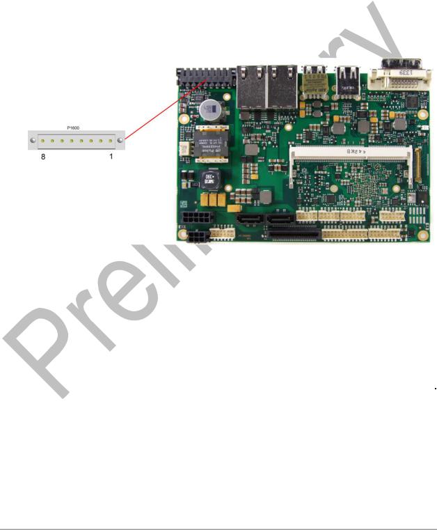
4.2 Power Supply
The power supply of the hardware module is realized via an 8pin connector (Weidmüller 180537-0000). The main 24V power lines are assigned to pins 5 and 6. An external Pb-battery can be connected to pins 1 and 2 to provide UPS functionality. Contact your sales person to discuss suitable battery packs.
Pin 3 (VOUT) is a 24V output (max. 2A), which is supported by the UPS (Pb-accu or capacitors) in the event of a power failure. One possible application would be to use this output to supply a display device which would then be able to display information about the power failure and the imminent system shutdown.
If a UPS is present you need to have a possibility to shut down the board in a regular way without activating the UPS, thereby preventing premature aging of UPS components. That's what pin 7 (PC_START) is for. When pulled high (24V) a regular shutdown without UPS activity is triggered. As a part of this regular shutdown pins 3 (VOUT) and 8 (PC_AKTIV) are pulled from 24V to 0V. Any devices connected to VOUT will thus also be switched off without discharging the UPS.
Pin |
Name |
Description |
|
|
|
1 |
GND |
ground |
2 |
BAT+ |
battery |
3 |
Vout |
output voltage |
4 |
S_GND |
ground (shield) |
5 |
P_VIN# |
power supply - |
6 |
P_VIN |
power supply + |
7 |
PC_START |
PC start |
8 |
PC_AKTIV |
power status |
Beckhoff New Automation Technology CB3063 |
page 17 |
Chapter: Connectors |
Power Connector |
|
|
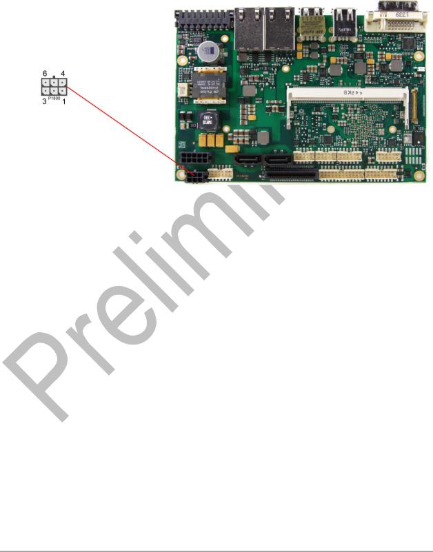
4.3 Power Connector
The board is equipped with a 2x3pin connector offering standard 5V and 12V power supplies for additional peripheral devices. Maximum current is 2 amperes for VCC/SVCC combined, and also 2 amperes for 12V. In the case of a power failure theses supplies are supported by the UPS circuit, but only if the UPS is a Pb-battery or if a SUPS is connected.
Pinout power connector Molex 2x3:
Description |
Name |
|
Pin |
Name |
Description |
|
|
|
|
|
|
|
|
ground |
GND |
1 |
|
4 |
VCC |
power supply 5V |
ground |
GND |
2 |
|
5 |
VCC |
power supply 5V |
power supply 3.3V |
3.3V |
3 |
|
6 |
12V |
power supply 12V |
page 18 |
Beckhoff New Automation Technology CB3063 |
Power Connector |
Chapter: Connectors |
|
|
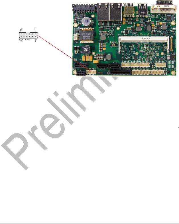
4.4 Power Connector
In addition the board is equipped with a 2x6pin connector (FCI 98424-G52-12LF, mating connector FCI 90311-012LF) offering standard 5V and 12V power supplies for additional peripheral devices. Maximum current is 2 amperes for VCC/SVCC combined, and also 2 amperes for 12V. In the case of a power failure theses supplies are supported by the UPS circuit, but only if the UPS is a Pb-battery or if a SUPS is connected.
Pinout Molex connector 2x6:
Description |
Name |
|
Pin |
Name |
Description |
|
|
|
|
|
|
|
|
power supply 5V |
VCC |
1 |
|
7 |
VCC |
power supply 5V |
power supply 5V |
VCC |
2 |
|
8 |
GND |
ground |
ground |
GND |
3 |
|
9 |
GND |
ground |
ground |
GND |
4 |
|
10 |
GND |
ground |
power supply 12V |
12V |
5 |
|
11 |
GND |
ground |
power supply 12V |
12V |
6 |
|
12 |
12V |
power supply 12V |
Beckhoff New Automation Technology CB3063 |
page 19 |
Chapter: Connectors |
SUSV |
|
|
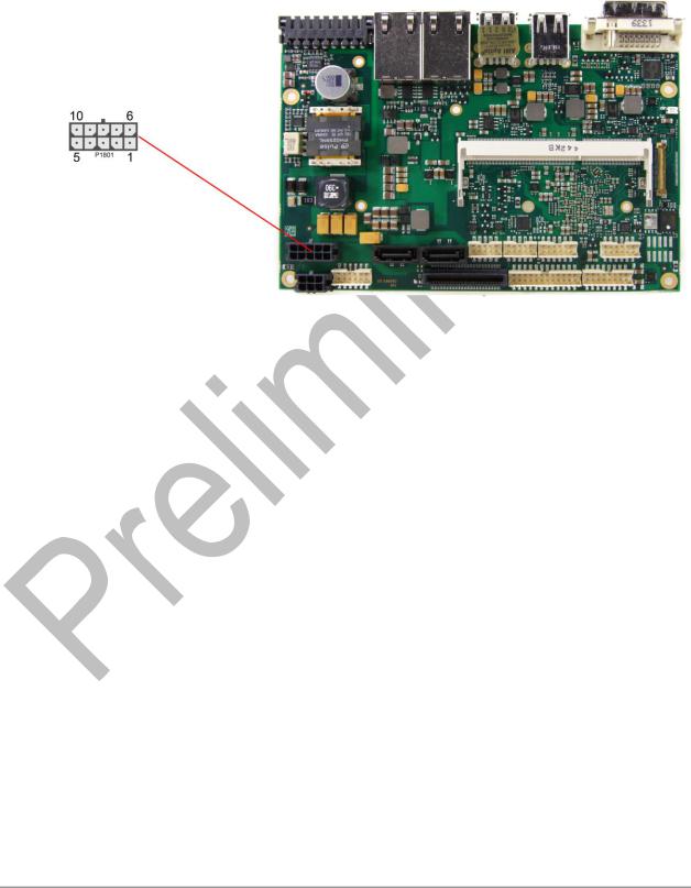
4.5 SUSV
A SUPS can be connected via a 2x6pin connector (Molex 43045-1013, mating connector Molex 43025-1013). Depending on the used capacity and the power consumption it is possible to hold power of the CB3063 for several seconds.
Pinout Molex 2x5:
Description |
Name |
|
Pin |
Name |
Description |
|
|
|
|
|
|
|
|
output voltage |
Voutreg |
1 |
|
6 |
Voutreg |
output voltage |
output voltage |
Vout |
2 |
|
7 |
Vout |
output voltage |
ground |
GND |
3 |
|
8 |
GND |
ground |
SUSV |
SUSV |
4 |
|
9 |
SMBALERT# |
SMB alert |
SMB data |
SMB-DAT |
5 |
|
10 |
SMB-CLK |
SMB clock |
page 20 |
Beckhoff New Automation Technology CB3063 |
System |
Chapter: Connectors |
|
|
4.6 System
A number of signals for system control and for SMBus communication are provided through a 2x12 pin connector (FCI 98424-G52-24LF, mating connector FCI 90311-024LF). This connector combines signals for power button, reset, keyboard, speaker, and several LEDs such as harddisk LED, and suspend LED, and three additional LEDs which are driven by GPIOs. Of these three GPIO-LEDs, LED1 and LED2 are already provided with a series resistor. SMBus capable devices can also be connected.
Pinout 2x12pin connector:
Description |
Name |
|
Pin |
Name |
Description |
|
|
|
|
|
|
|
|
ground |
GND |
1 |
|
13 |
3.3V |
3.3V supply |
reset to ground |
RSTBTN# |
2 |
|
14 |
PWRBTN# |
on/suspend button |
LED suspend / ACPI |
S-LED |
3 |
|
15 |
S3.3V |
standby supply 3.3V |
LED harddisk |
SATALED |
4 |
|
16 |
GPIOLED3 |
LED GPIO device 3 |
LED GPIO device 1 |
GPIOLED1 |
5 |
|
17 |
BATT |
battery |
LED GPIO device 2 |
GPIOLED2 |
6 |
|
18 |
SMBALERT# |
SMB alert |
SMB Clock |
SMBCLKEX |
7 |
|
19 |
SMBDATEX |
SMB data |
speaker to 5V |
SPEAKER |
8 |
|
20 |
SVCC |
standby supply 5V |
keyboard clock |
KCLK |
9 |
|
21 |
KDAT |
keyboard data |
ground |
GND |
10 |
|
22 |
VCC |
5V supply |
ground |
GND |
11 |
|
23 |
VCC |
5V supply |
ground |
GND |
12 |
|
24 |
VCC |
5V supply |
Beckhoff New Automation Technology CB3063 |
page 21 |
Chapter: Connectors |
Memory |
|
|
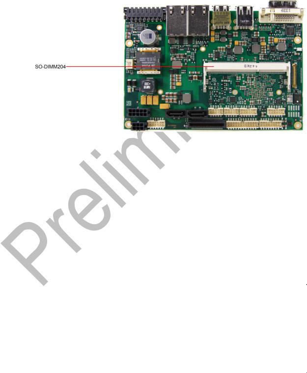
4.7 Memory
Conventional SO-DIMM204 memory modules, as familiar from notebook computers, are used to equip the board with memory. For technical and mechanical reasons it is possible that particular memory modules cannot be employed. Please ask your distributor for recommended memory modules.
With currently available SO-DIMM204 modules a memory extension up to 8 GByte is possible (DDR3L-1333).
All timing parameters for different memory modules are automatically set by BIOS.
Pinout SO-DIMM204:
Description |
Name |
|
Pin |
|
Name |
Description |
|
|
|
|
|
|
|
|
|
memory reference current |
REF-DQ |
1 |
|
2 |
|
GND |
ground |
ground |
GND |
3 |
|
4 |
|
DQ4 |
data 4 |
data 0 |
DQ0 |
5 |
|
6 |
|
DQ5 |
data 5 |
data 1 |
DQ1 |
7 |
|
8 |
|
GND |
ground |
ground |
GND |
9 |
|
10 |
|
DQS0# |
data strobe 0 - |
data mask 0 |
DM0 |
11 |
|
12 |
|
DQS0 |
data strobe 0 + |
ground |
GND |
13 |
|
14 |
|
GND |
ground |
data 2 |
DQ2 |
15 |
|
16 |
|
DQ6 |
data 6 |
data 3 |
DQ3 |
17 |
|
18 |
|
DQ7 |
data 7 |
ground |
GND |
19 |
|
20 |
|
GND |
ground |
data 8 |
DQ8 |
21 |
|
22 |
|
DQ12 |
data 12 |
data 9 |
DQ9 |
23 |
|
24 |
|
DQ13 |
data 13 |
ground |
GND |
25 |
|
26 |
|
GND |
ground |
data strobe 1 - |
DQS1# |
27 |
|
28 |
|
DM1 |
data mask 1 |
data strobe 1 + |
DQS1 |
29 |
|
30 |
|
RESET# |
Reset |
ground |
GND |
31 |
|
32 |
|
GND |
ground |
data 10 |
DQ10 |
33 |
|
34 |
|
DQ14 |
data 14 |
data 11 |
DQ11 |
35 |
|
36 |
|
DQ15 |
data 15 |
ground |
GND |
37 |
|
38 |
|
GND |
ground |
data 16 |
DQ16 |
39 |
|
40 |
|
DQ20 |
data 20 |
data 17 |
DQ17 |
41 |
|
42 |
|
DQ21 |
data 21 |
ground |
GND |
43 |
|
44 |
|
GND |
ground |
data strobe 2 - |
DQS2# |
45 |
|
46 |
|
DM2 |
data mask 2 |
data strobe 2 + |
DQS2 |
47 |
|
48 |
|
GND |
ground |
ground |
GND |
49 |
|
50 |
|
DQ22 |
data 22 |
|
|
|
|
|
|
|
|
page 22 |
|
|
|
|
Beckhoff New Automation Technology CB3063 |
||

Memory |
|
|
|
|
|
Chapter: Connectors |
|
|
|
|
|
|
|
|
|
|
|
|
|
|
Description |
Name |
|
Pin |
Name |
Description |
|
|
|
|
|
|
|
|
data 18 |
DQ18 |
51 |
|
52 |
DQ23 |
data 23 |
data 19 |
DQ19 |
53 |
|
54 |
GND |
ground |
ground |
GND |
55 |
|
56 |
DQ28 |
data 28 |
data 24 |
DQ24 |
57 |
|
58 |
DQ29 |
data 29 |
data 25 |
DQ25 |
59 |
|
60 |
GND |
ground |
ground |
GND |
61 |
|
62 |
DQS3# |
data strobe 3 - |
data mask 3 |
DQM3 |
63 |
|
64 |
DQS3 |
data strobe 3 + |
ground |
GND |
65 |
|
66 |
GND |
ground |
data 26 |
DQ26 |
67 |
|
68 |
DQ30 |
data 30 |
data 27 |
DQ27 |
69 |
|
70 |
DQ31 |
data 31 |
ground |
GND |
71 |
|
72 |
GND |
ground |
clock enables 0 |
CKE0 |
73 |
|
74 |
CKE1 |
clock enables 1 |
1.5 volt supply |
1.5V |
75 |
|
76 |
1.5V |
1.5 volt supply |
reserved |
N/C |
77 |
|
78 |
(A15) |
reserved |
SDRAM bank 2 |
BA2 |
79 |
|
80 |
A14 |
address 14 |
1.5 volt supply |
1.5V |
81 |
|
82 |
1.5V |
1.5 volt supply |
address 12 (burst chop) |
A12/BC# |
83 |
|
84 |
A11 |
address 11 |
address 9 |
A9 |
85 |
|
86 |
A7 |
address 7 |
1.5 volt supply |
1.5V |
87 |
|
88 |
1.5V |
1.5 volt supply |
address 8 |
A8 |
89 |
|
90 |
A6 |
address 6 |
address 5 |
A5 |
91 |
|
92 |
A4 |
address 4 |
1.5 volt supply |
1.5V |
93 |
|
94 |
1.5V |
1.5 volt supply |
address 3 |
A3 |
95 |
|
96 |
A2 |
address 2 |
address 1 |
A1 |
97 |
|
98 |
A0 |
address 0 |
1.5 volt supply |
1.5V |
99 |
|
100 |
1.5V |
1.5 volt supply |
Clock 0 + |
CK0 |
101 |
|
102 |
CK1 |
clock 1 + |
Clock 0 - |
CK0# |
103 |
|
104 |
CK1# |
clock 1 - |
1.5 volt supply |
1.5V |
105 |
|
106 |
1.5V |
1.5 volt supply |
address 10 (auto precharge) |
A10/AP |
107 |
|
108 |
BA1 |
SDRAM bank 1 |
SDRAM Bank 0 |
BA0 |
109 |
|
110 |
RAS# |
row address strobe |
1.5 volt supply |
1.5V |
111 |
|
112 |
1.5V |
1.5 volt supply |
write enable |
WE# |
113 |
|
114 |
S0# |
chip select 0 |
column address strobe |
CAS# |
115 |
|
116 |
ODT0 |
on die termination 0 |
1.5 volt supply |
1.5V |
117 |
|
118 |
1.5V |
1.5 volt supply |
address 13 |
A13 |
119 |
|
120 |
ODT1 |
on die termination 1 |
Chip Select 1 |
S1# |
121 |
|
122 |
N/C |
reserved |
1.5 volt supply |
1.5V |
123 |
|
124 |
1.5V |
1.5 volt supply |
reserved |
(TEST) |
125 |
|
126 |
REF-CA |
reference current |
ground |
GND |
127 |
|
128 |
GND |
ground |
data 32 |
DQ32 |
129 |
|
130 |
DQ36 |
data 36 |
data 33 |
DQ33 |
131 |
|
132 |
DQ37 |
data 37 |
ground |
GND |
133 |
|
134 |
GND |
ground |
data strobe 4 - |
DQS4# |
135 |
|
136 |
DQM4 |
data mask 4 |
data strobe 4 + |
DQS4 |
137 |
|
138 |
GND |
ground |
ground |
GND |
139 |
|
140 |
DQ38 |
data 38 |
data 34 |
DQ34 |
141 |
|
142 |
DQ39 |
data 39 |
data 35 |
DQ35 |
143 |
|
144 |
GND |
ground |
ground |
GND |
145 |
|
146 |
DQ44 |
data 44 |
data 40 |
DQ40 |
147 |
|
148 |
DQ45 |
data 45 |
data 41 |
DQ41 |
149 |
|
150 |
GND |
ground |
ground |
GND |
151 |
|
152 |
DQS5# |
data strobe 5 - |
data mask 5 |
DQM5 |
153 |
|
154 |
DQS5 |
data strobe 5 + |
ground |
GND |
155 |
|
156 |
GND |
ground |
data 42 |
DQ42 |
157 |
|
158 |
DQ46 |
data 46 |
data 43 |
DQ43 |
159 |
|
160 |
DQ47 |
data 47 |
Beckhoff New Automation Technology CB3063 |
page 23 |

Chapter: Connectors |
|
|
|
|
|
Memory |
|
|
|
|
|
|
|
|
|
|
|
|
|
|
Description |
Name |
|
Pin |
Name |
Description |
|
|
|
|
|
|
|
|
ground |
GND |
161 |
|
162 |
GND |
ground |
data 48 |
DQ48 |
163 |
|
164 |
DQ52 |
data 52 |
data 49 |
DQ49 |
165 |
|
166 |
DQ53 |
data 53 |
ground |
GND |
167 |
|
168 |
GND |
ground |
data strobe 6 - |
DQS6# |
169 |
|
170 |
DQM6 |
data mask 6 |
data strobe 6 |
DQS6 |
171 |
|
172 |
GND |
ground |
ground |
GND |
173 |
|
174 |
DQ54 |
data 54 |
data 50 |
DQ50 |
175 |
|
176 |
DQ55 |
data 55 |
data 51 |
DQ51 |
177 |
|
178 |
GND |
ground |
ground |
GND |
179 |
|
180 |
DQ60 |
data 60 |
data 56 |
DQ56 |
181 |
|
182 |
DQ61 |
data 61 |
data 57 |
DQ57 |
183 |
|
184 |
GND |
ground |
ground |
GND |
185 |
|
186 |
DQS7# |
data strobe 7 - |
data mask 7 |
DQM7 |
187 |
|
188 |
DQS7 |
data strobe 7 + |
ground |
GND |
189 |
|
190 |
GND |
ground |
data 58 |
DQ58 |
191 |
|
192 |
DQ62 |
data 62 |
data 59 |
DQ59 |
193 |
|
194 |
DQ63 |
data 63 |
ground |
GND |
195 |
|
196 |
GND |
ground |
SPD address 0 |
SA0 |
197 |
|
198 |
EVENT# |
Event |
3.3 volt supply |
3.3V |
199 |
|
200 |
SDA |
SMBus data |
SPD address 1 |
SA1 |
201 |
|
202 |
SCL |
SMBus clock |
termination current |
VTT |
203 |
|
204 |
VTT |
termination current |
page 24 |
Beckhoff New Automation Technology CB3063 |
VGA/DVI |
Chapter: Connectors |
|
|
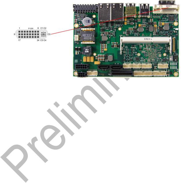
4.8 VGA/DVI
The module is equipped with a standard DVI-I-connector, which can be used to connect a DVI capable device, a standard VGA monitor or an HDMI capable device. External cable adapters that convert from DVI to VGA or HDMI are required to connect standard VGA or HDMI devices.
Pinout DVI-I:
Pin |
Name |
|
Description |
|
|
|
|
1 |
TMDSDAT2# |
DVI data 2 - |
|
2 |
TMDSDAT2 |
DVI data 2 + |
|
3 |
GND |
ground |
|
4 |
N/C |
reserved |
|
5 |
N/C |
reserved |
|
6 |
DDC CLK |
DDC clock (DVI/VGA) |
|
7 |
DDC DAT |
DDC data (DVI/VGA) |
|
8 |
VSYNC |
VGA vertical sync |
|
9 |
TMDSDAT1# |
DVI data 1 - |
|
10 |
TMDSDAT1 |
DVI data 1 + |
|
11 |
GND |
ground |
|
12 |
N/C |
reserved |
|
13 |
N/C |
reserved |
|
14 |
VCC |
5 volt supply |
|
15 |
GND |
ground |
|
16 |
HP_DETECT |
hot plug detect |
|
17 |
TMDSDAT0# |
DVI data 0 - |
|
18 |
TMDSDAT0 |
DVI data 0 + |
|
19 |
GND |
ground |
|
20 |
N/C |
reserved |
|
21 |
N/C |
reserved |
|
22 |
GND |
ground |
|
23 |
TMDS CLK |
DVI clock |
|
24 |
TMDS CLK# |
DVI clock |
|
C1 |
RED |
VGA red |
|
C2 |
GREEN |
VGA green |
|
C3 |
BLUE |
VGA blue |
|
C4 |
HSYNC |
VGA horizontal sync |
|
|
|
|
|
Beckhoff New Automation Technology CB3063 |
page 25 |
||

Chapter: Connectors |
VGA/DVI |
|
|
|
|
|
|
|
Pin |
Name |
Description |
|
|
|
C5 |
GND |
ground |
page 26 |
Beckhoff New Automation Technology CB3063 |
DVI/HDMI/DisplayPort |
Chapter: Connectors |
|
|
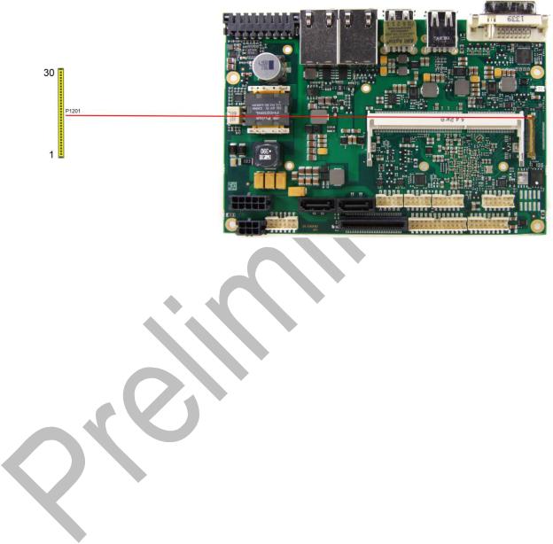
4.9 DVI/HDMI/DisplayPort
The CB3063 provides a second DVI interface which is realized as a 30pin flat cable header (I-PEX Cabline-VS 20455-030E-12). Analog VGA is not available on this connector. However, an HDMI device or DisplayPort device can be connected. This custom connector also carries an additional USB interface. Please note that a custom cable design is required.
Pinout 30pin connector DVI/HDMI/DisplayPort:
Pin |
Name |
|
Description |
|
|
|
|
1 |
TMDS0#/DP2# |
DVI Data 0 - / DP Lane 2 - |
|
2 |
TMDS0/DP2 |
DVI Data 0 + / DP Lane 2 + |
|
3 |
TMDS1#/DP1# |
DVI Data 1 - / DP Lane 1 - |
|
4 |
TMDS1/DP1 |
DVI Data 1 + / DP Lane 1 + |
|
5 |
TMDS2#/DP0# |
DVI Data 2 - / DP Lane 0 - |
|
6 |
TMDS2/DP0 |
DVI Data 2 + / DP Lane 0 + |
|
7 |
TMDSCLK#/DP3# |
DVI Clock - / DP Lane 3 - |
|
8 |
TMDSCLK/DP3 |
DVI Clock + / DP Lane 3 + |
|
9 |
N/C |
reserved |
|
10 |
SEL_DVI/DP# |
DVI-DisplayPort Select |
|
11 |
DDCK/DPAUX |
EDID Clock / DP Aux + |
|
12 |
DDDA/DPAUX# |
EDID Data / DP Aux - |
|
13 |
VCC |
5V supply |
|
14 |
GND |
ground |
|
15 |
HPD |
hot plug detect |
|
16 |
USBVCC |
5V supply for USB |
|
17 |
USBVCC |
5V supply for USB |
|
18 |
N/C |
reserved |
|
19 |
N/C |
reserved |
|
20 |
SSTX# |
Super Speed receiver - |
|
21 |
SSTX |
Super Speed receiver + |
|
22 |
USB# |
USB - |
|
23 |
USB |
USB + |
|
24 |
SSRX# |
Super Speed transmitter - |
|
25 |
SSRX |
Super Speed transmitter |
|
26 |
3.3V |
3.3V supply |
|
27 |
3.3V |
3.3V supply |
|
|
|
|
|
Beckhoff New Automation Technology CB3063 |
page 27 |
||

Chapter: Connectors |
DVI/HDMI/DisplayPort |
|
|
|
|
|
|
|
Pin |
Name |
Description |
|
|
|
28 |
VCC |
5V supply |
29 |
VCC |
5V supply |
30 |
VCC |
5V supply |
page 28 |
Beckhoff New Automation Technology CB3063 |
 Loading...