


Beckhoff PC Fieldbuscard
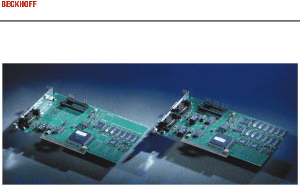
PCI CANopen FC5101 and FC5102
CANopen PCI Card FC5101,
FC5102
Last change: 31.10.2002

Eiserstraße 5 / D-33415 Verl / Telefon 05246/963-0 / Telefax 05246/963-149
3
Contents
CANopen PCI Card FC5101, FC5102
1. Foreword |
5 |
Notes on the Manual |
5 |
Safety Instrutions |
6 |
Version of the Documentation |
7 |
2. Product Overview |
8 |
Technical Documentation |
8 |
CANopen Introduction |
9 |
Hardware Description |
11 |
3. |
Fitting and wiring |
13 |
|
Installation |
13 |
|
Wiring the Bus System |
14 |
4. |
Parameterisation and Commissioning |
20 |
|
Configuration: TwinCAT System Manager |
20 |
|
Beckhoff Bus Coupler |
28 |
|
CANopen Device |
30 |
|
CANopen eds Files |
34 |
5. |
CANopen Communication |
35 |
|
Network Management |
35 |
|
BootUp of the FC510x |
39 |
|
Process data Objects (PDO) |
42 |
|
PDO Parameterisation |
49 |
|
Service data objects |
51 |
|
FC501x: SDO Communication |
55 |
|
Baud rate and Bit Timing |
60 |
|
Identifier Allocation |
61 |
6. Error Handling and Diagnosis |
62 |
|
|
LEDs |
62 |
|
Bus Node Diagnostics |
63 |
|
Diagnostics FC510x |
66 |
|
Emergency Messages |
68 |
|
ADS error codes |
69 |

Eiserstraße 5 / D-33415 Verl / Telefon 05246/963-0 / Telefax 05246/963-149
4
|
Trouble Shooting |
73 |
7. |
Bus Trace Function |
76 |
|
FC510x as a CANopen Monitor |
76 |
8. |
Appendix |
83 |
|
Identifier Full List |
83 |
|
License |
92 |
|
List of Literature |
93 |
|
List of Abbreviations |
94 |
|
Support |
95 |

Eiserstraße 5 / D-33415 Verl / Telefon 05246/963-0 / Telefax 05246/963-149
5
1. Foreword
Notes on the Manual
This description is only intended for the use of trained specialists in control and automation engineering who are familiar with the applicable national standards. It is essential that the following notes and explanations are followed when installing and commissioning these components.
Liability Conditions
The responsible staff must ensure that the application or use of the products described satisfy all the requirements for safety, including all the relevant laws, regulations, guidelines and standards.
The documentation has been prepared with care. The products described are, however, constantly under development. For that reason the documentation is not in every case checked for consistency with performance data, standards or other characteristics, and does not represent an assurance of characteristics in the sense of § 459, Para. 2 of the German Civil Code. In the event that it contains technical or editorial errors, we retain the right to make alterations at any time and without warning. No claims for the modification of products that have already been supplied may be made on the basis of the data, diagrams and descriptions in this documentation.
© This manual is copyrighted. Any reproduction or third party use of this publication, whether in whole or in part, without the written permission of Elektro Beckhoff GmbH, is forbidden.
Eiserstraße 5 / D-33415 Verl / Telefon 05246/963-0 / Telefax 05246/963-149
6
Safety Instructions
Safety Rules
The responsible staff must ensure that the application or use of the products described satisfy all the requirements for safety, including all the relevant laws, regulations, guidelines and standards.
State at Delivery
All the components are supplied in particular hardware and software configurations appropriate for the application. Modifications to hardware or software configurations other than those described in the documentation are not permitted, and nullify the liability of Elektro Beckhoff GmbH.
Personnel Qualification
This description is only intended for the use of trained specialists in control and automation engineering who are familiar with the applicable national standards.
Description of safety symbols
The following safety symbols are used in this operating manual. They are intended to alert the reader to the associated safety instructions.
 Danger This symbol is intended to highlight risks for the life or health of personnel.
 Warning This symbol is intended to highlight risks for equipment, materials or the environment.
Note |
This symbol indicates information that contributes to better understanding. |

Eiserstraße 5 / D-33415 Verl / Telefon 05246/963-0 / Telefax 05246/963-149
7
Version of the Documentation
Version |
Changes |
|
|
0.9 (Pre-Release) |
Prelimary Version, 11.3.2002 |
|
|
1.0 |
completely revised |
|
- FC510x Monitor Software documented |
|
- CANopen Protocol description revised |
The using of the FC5101 in the slave mode is described separately (FC510x Slave.chm resp. -.pdf).
Eiserstraße 5 / D-33415 Verl / Telefon 05246/963-0 / Telefax 05246/963-149
8
2. Product Overview
Beckhoff FC510x: Technical Documentation
The FC510x is a CANopen master card with the following features:
One (FC5101) or two (FC5102) CAN channels, each with its own processor, memory, etc.
Optionally CANopen master or slave
All PDO communication types are supported
Each PDO can be individually monitored
Host communication may be free running, synchronised or equidistant
Equidistant mode for drive regulation over the bus: SYNC objects are transmitted with a mean timing having the accuracy of the quartz oscillator, while process data exchange with the application is synchronised throughout (only with TwinCAT).
Emergency messages are stored by the card
Error handling can be set individually for each bus node
General CAN messages (CAN layer 2) can be sent and received
Powerful parameter and diagnostics interface
Integrated bus loading display
CAN interfaces are electrically isolated
Meets CANopen specification DS301 V4.01
Boot-up according to DS302
Drivers: TwinCAT I/O for WinNT, Win2k, WinXP;
Driver Construction Kit for other operating systems by request
See the appropriate separate documentation for details of slave functionality.
Eiserstraße 5 / D-33415 Verl / Telefon 05246/963-0 / Telefax 05246/963-149
9
CANopen Introduction
CANopen is a widely used CAN application layer, developed by the CAN in Automation association, and which has meanwhile been adopted for international standardisation.
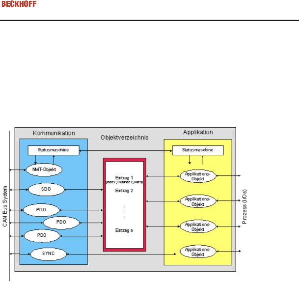
Device Model
CANopen consists of the protocol definitions (communication profile) and of the device profiles that standardise the data contents for the various device classes. Process data objects (PDO).are used for fast communication of input and output data. The CANopen device parameters and process data are stored in a structured object directory. Any data in this object directory is accessed via service data objects (SDO). There are, additionally, a few special objects (such as telegram types) for network management (NMT), synchronisation, error messages and so on.
Communication Types
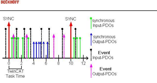
CANopen defines a number of communication classes for the input and output data (process data objects):
Event driven: Telegrams are sent as soon as their contents have changed. This means that the process image as a whole is not continuously transmitted, only its changes.
Cyclic synchronous: A SYNC telegram causes the modules to accept the output data that was previously received, and to send new input data.
Requested: A CAN data request telegram causes the modules to send their input data.
The desired communication type is set by the "Transmission Type" parameter.
Device Profile
The Beckhoff CANopen devices support all types of I/O communication, and correspond to the device profile for digital and analog input/output modules (DS401).
The default mapping has not been adapted to the profile version DS401 V2 because of the downward compatibility.
Transmission Rates
Nine transmission rates from 10 kbaud up to 1 Mbaud are available for different bus lengths. The effective utilisation of the bus bandwidth allows CANopen to achieve short system reaction times at relatively low data rates.

Eiserstraße 5 / D-33415 Verl / Telefon 05246/963-0 / Telefax 05246/963-149
10
Topology
CAN is based on a linear topology. The number of devices participating in each network is logically limited by CANopen to 128, but physically the present generation of drivers allows up to 64 nodes in one network segment. The maximum possible size of the network for any particular data rate is limited by the signal transit time required on the bus medium. For 1 Mbaud, for instance, the network may extend 25 m, whereas at 50 kbaud the network may reach up to 1000 m. At low data rates the size of the network can be increased by repeaters, which also allow the construction of tree structures.
Bus access procedures
CAN utilises the Carrier Sense Multiple Access (CSMA) procedure, i.e. all participating devices have the same right of access to the bus and may access it as soon as it is free (multi-master bus access). The exchange of messages is thus not device-oriented but message-oriented. This means that every message is unambiguously marked with a prioritised identifier. In order to avoid collisions on the bus when messages are sent by different devices, a bit-wise bus arbitration is carried out at the start of the data transmission. The bus arbitration assigns bus bandwidth to the messages in the sequence of their priority. At the end of the prioritisation phase only one bus device occupies the bus, collisions are avoided and the bandwidth is optimally exploited.
Configuration and parameterisation
The TwinCAT System Manager allows all the CANopen parameters to be set conveniently. An "eds" file (an electronic data sheet) is available on the Beckhoff website for the parameterisation of Beckhoff CANopen devices using configuration tools from other manufacturers.
Certification
The Beckhoff CANopen devices have a powerful implementation of the protocol, and are certified by CiA, the CAN in Automation association.
Eiserstraße 5 / D-33415 Verl / Telefon 05246/963-0 / Telefax 05246/963-149
11
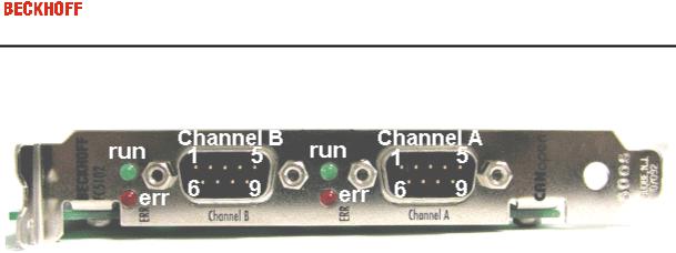
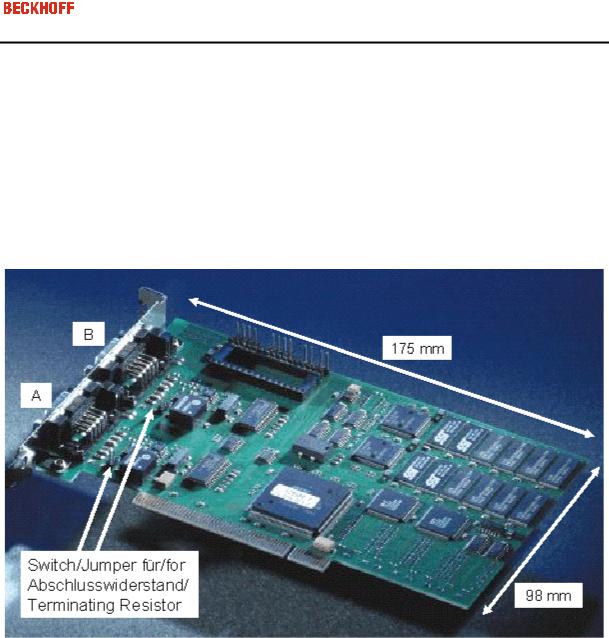
Beckhoff FC510x Hardware Description
CAN Terminating Resistor
On the card there are CAN terminating resistors (120 Ohms). These can be activated with a jumper (up to hardware version 3) or with a switch (from hardware version 4) close to the CAN connectors.
The Flash Disk Socket is currently not in use.
Pin out
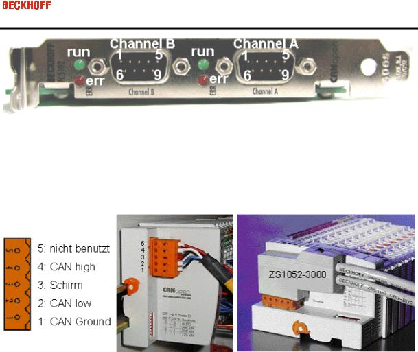
The CAN network is connected via 9-pin DB9 sockets with the following pin out:.
Pin |
Pin Out |
|
|
2CAN low (CAN-)
3CAN Ground (internally connected with Pin 6)
5Shield
6CAN Ground (internally connected with Pin 3)
7CAN high (CAN+)
Eiserstraße 5 / D-33415 Verl / Telefon 05246/963-0 / Telefax 05246/963-149
12
The pins not mentioned here are not connected.
Note: An auxiliary power up to 30VDC may be connected to Pin 9 (some CAN Devices use this auxiliary power e.g. for transceiver supply).
Eiserstraße 5 / D-33415 Verl / Telefon 05246/963-0 / Telefax 05246/963-149
13
3. Fitting and wiring
Installation
 Fieldbus PCI cards may only be fitted by qualified personnel in accordance and the following points must be observed.
In order to protect the card from electrostatic discharge the user must be discharged before handling the card or the PC.
Before opening the PC housing it must be switched off, and the mains plug must be removed.
In may be necessary before fitting to set the jumper in order to activate the internal CAN bus terminating resistors, or to set the switch (as from hardware version 3). The jumper being set or the switch being on means that the terminating resistor is connected.
The card can be fitted into any free PCI slot. Ensure that the PCI bus connector is making good contact, and that the module is seated firmly. Fasten the module to the PC slot housing with the fixing screw.
Eiserstraße 5 / D-33415 Verl / Telefon 05246/963-0 / Telefax 05246/963-149
14
Wiring the Bus System
Section summary:
CAN topology
Bus length
Drop lines
Star hub
CAN cable
Screening
Cable colours
FC510x: D-sub, 9 pin
BK51x0: 5- pin open style connector
LC5100 bus connection
Fieldbus Box: M 12 CAN socket
Notes related to checking the CAN wiring can be found in the Trouble Shooting section.
CAN topology
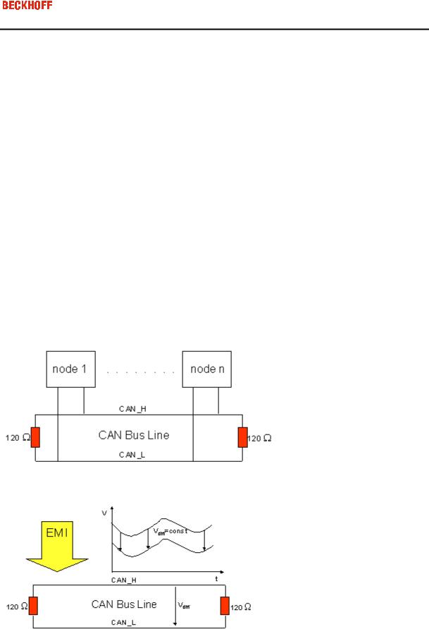
CAN is a 2-wire bus system, to which all participating devices are connected in parallel (i.e. using short drop lines). The bus must be terminated at each end with a 120 (or 121) Ohm terminating resistor to prevent reflections. This is also necessary even if the cable lengths are very short!
Since the CAN signals are represented on the bus as the difference between the two levels, the CAN leads are not very sensitive to incoming interference (EMI): Both leads are affected, so the interference has very little effect on the difference.
Bus length
The maximum length of a CAN bus is primarily limited by the signal transit time. The multi-master bus access procedure (arbitration) requires signals to reach all the nodes at effectively the same time (before the sampling within a bit period). Since the signal transit times in the CAN connecting equipment (transceivers, opto-
Eiserstraße 5 / D-33415 Verl / Telefon 05246/963-0 / Telefax 05246/963-149
15
couplers, CAN controllers) are almost constant, the line length must be chosen in accordance with the baud rate:
|
Baud Rate |
|
|
Bus length |
|
|
|
|
|
||
|
|
|
|
|
|
|
1 Mbit/s |
|
|
< 20 m* |
|
|
500 kbit/s |
|
|
< 100 m |
|
|
|
|
|
|
|
|
250 kbit/s |
|
|
< 250 m |
|
|
125 kbit/s |
|
|
< 500 m |
|
|
|
|
|
|
|
|
50 kbit/s |
|
|
< 1000 m |
|
|
|
|
|
|
|
|
20 kbit/s |
|
|
< 2500 m |
|
|
10 kbit/s |
|
|
< 5000 m |
|
|
|
|
|
|
|
*) A figure of 40m at 1 Mbit/s is often found in the CAN literature. This does not, however, apply to networks with optically isolated CAN controllers. The worst case calculation for opto-couplers yields a figure 5 m at 1 Mbit/s - in practice, however, 20 m can be reached without difficulty.
It may be necessary to use repeaters for bus lengths greater than 1000 m.
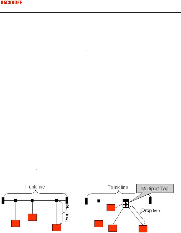
Drop lines
Drop lines must always be avoided as far as possible, since they inevitably cause reflections. The reflections caused by drop lines are not however usually critical, provided they have decayed fully before the sampling time. In the case of the bit timing settings selected in the bus couplers it can be assumed that this is the case, provided the following drop line lengths are not exceeded:
|
Baud Rate |
|
|
Drop line length |
|
|
Total length of all drop lines |
|
|
|
|
|
|
|
|||
|
|
|
|
|
|
|
|
|
|
1 Mbit/s |
|
|
< 1m |
|
|
< 5 m |
|
|
500 kbit/s |
|
|
< 5 m |
|
|
< 25 m |
|
|
|
|
|
|
|
|
|
|
|
250 kbit/s |
|
|
< 10m |
|
|
< 50 m |
|
|
125 kbit/s |
|
|
< 20m |
|
|
< 100 m |
|
|
|
|
|
|
|
|
|
|
|
50 kbit/s |
|
|
< 50m |
|
|
< 250 m |
|
|
|
|
|
|
|
|
|
|
Drop lines must not have terminating resistors.
Star Hub (Multiport Tap)
Shorter drop line lengths must be maintained when passive distributors ("multiport taps"), such as the Beckhoff ZS5052-4500 Distributor Box. The following table indicates the maximum drop line lengths and the maximum length of the trunk line (without the drop lines):
|
Baud Rate |
|
|
Drop line length with multiport topology |
|
|
Trunk line length (without drop lines) |
|
|
|
|
|
|
|
|||
|
|
|
|
|
|
|
|
|
|
1 Mbit/s |
|
|
< 0,3 m |
|
|
< 25 m |
|
|
500 kbit/s |
|
< 1,2 m |
|
|
< 66 m |
|
|
|
|
|
|
|
|
|
|
|
|
250 kbit/s |
|
< 2,4 m |
|
|
< 120 m |
|
|
|
125 kbit/s |
|
< 4.8 m |
|
|
< 310 m |
|
|
Eiserstraße 5 / D-33415 Verl / Telefon 05246/963-0 / Telefax 05246/963-149
16
CAN cable
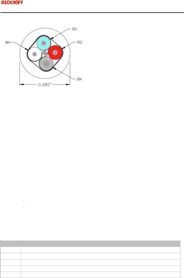
Screened twisted-pair cables (2x2) with a characteristic impedance of between 108 and 132 Ohm is recommended for the CAN wiring. If the CAN transceiver’s reference potential (CAN ground) is not to be connected, the second pair of conductors can be omitted. (This is only recommended for networks of small physical size with a common power supply for all the participating devices).
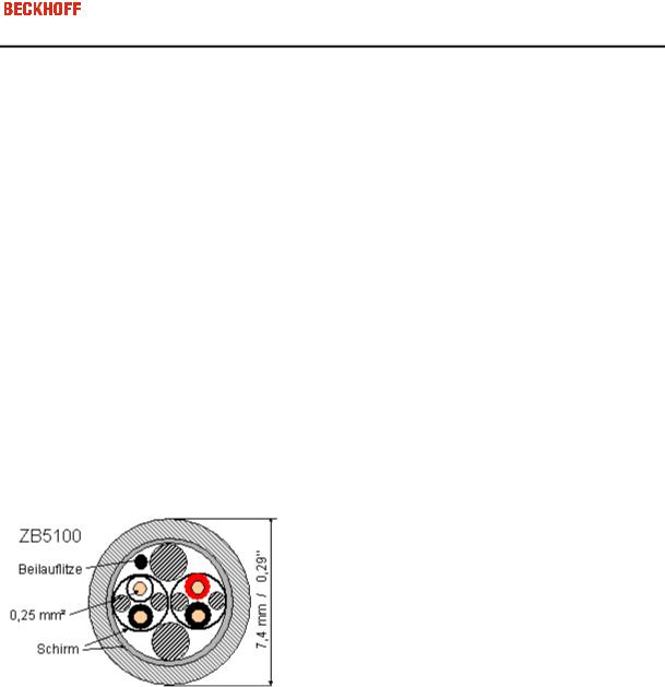
ZB5100 CAN Cable
A high quality CAN cable with the following properties is included in Beckhoff's range:
2 x 2 x 0.25 mm² (AWG 24) twisted pairs, cable colours: red/black + white/black
double screened
braided screen with filler strand (can be attached directly to pin 3 of the 5-pin connection terminal),
flexible (minimum bending radius 35 mm when bent once, 70 mm for repeated bending)
characteristic impedance (60 kHz): 120 Ohm
conductor resistance < 80 Ohm/km
sheath: grey PVC, external diameter 7.3 +/- 0.4 mm
Weight: 64 kg/km.
printed with "BECKHOFF ZB5100 CAN-BUS 2x2x0.25" and metre marking (length data every 20cm)
ZB5200 CAN/DeviceNet Cable
The ZB5200 cable material corresponds to the DeviceNet specification, and is also suitable for CANopen systems. The ready-made ZK1052-xxxx-xxxx bus cables for the Fieldbus Box modules are made from this cable material. It has the following specification:
2 x 2 x 0.34 mm² (AWG 22) twisted pairs
double screened braided screen with filler strand
characteristic impedance (1 MHz): 126 Ohm
conductor resistance 54 Ohm/km
sheath: grey PVC, external diameter 7.3 mm
printed with "InterlinkBT DeviceNet Type 572" as well as UL and CSA ratings
stranded wire colours correspond to the DeviceNet specification
UL recognised AWM Type 2476 rating
CSA AWM I/II A/B 80°C 300V FT1
Eiserstraße 5 / D-33415 Verl / Telefon 05246/963-0 / Telefax 05246/963-149
17
corresponds to the DeviceNet "Thin Cable" specification
Screening
The screen is to be connected over the entire length of the bus cable, and only galvanically grounded at one point, in order to avoid ground loops.
The design of the screening, in which HF interference is diverted through R/C elements to the mounting rail assumes that the rail is appropriately earthed and free from interference. If this is not the case, it is possible that HF interference will be transmitted from the mounting rail to the screen of the bus cable. In that case the screen should not be attached to the couplers - it should nevertheless still be fully connected through.
Notes related to checking the CAN wiring can be found in the Trouble Shooting section.
Cable colours
Suggested method of using the Beckhoff CAN cable on Bus Terminal and Fieldbus Box:
|
BK51x0 |
|
|
Fieldbus Box |
|
|
FC510x |
|
|
|
ZB5100 cable co- |
|
|
ZB5200 cable co- |
|
|
|
|
|
|
|
|
|
|
|
|
|||||
|
pin |
|
|
pin |
|
|
pin |
|
Function |
|
lour |
|
|
lour |
|
|
|
|
|
|
|
|
|
|
|
|
|
|
|
|
|
|
1 |
|
3 |
|
3 |
|
CAN |
|
black/ (red) |
|
|
black |
|
||
|
|
|
|
|
|
|
|
|
Ground |
|
|
|
|
|
|
|
2 |
|
5 |
|
2 |
|
CAN Low |
|
black |
|
|
blue |
|
||
|
|
|
|
|
|
|
|
|
|
|
|
|
|||
|
3 |
|
1 |
|
5 |
|
Screen |
|
Filler strand |
|
Filler strand |
|
|||
|
4 |
|
4 |
|
7 |
|
CAN high |
|
white |
|
|
white |
|
||
|
5 |
|
2 |
|
9 |
|
not used |
|
(red) |
|
|
(red) |
|
||
|
|
|
|
|
|
|
|
|
|
|
|
|
|
|
|
FC510x: D-sub, 9 pin
The CAN bus cable is connected to the FC5101 and FC5102 CANopen PCI cards via 9-pin sub-D sockets, with pins assigned as follows.
Pin Assignment
2CAN low (CAN-)
3CAN ground (internally connected to pin 6)
5Screen
6CAN ground (internally connected to pin 3)
7CAN high (CAN+)
The unlisted pins are not connected.
Note: An auxiliary voltage of up to 30 V DC may be connected to pin 9. Some CAN devices use this to supply the transceiver.
Eiserstraße 5 / D-33415 Verl / Telefon 05246/963-0 / Telefax 05246/963-149
18
BK51x0: 5- pin open style connector
The BK51x0 Bus Couplers have a recessed front surface on the left hand side with a five pin connector. The supplied CANopen socket can be inserted here.
The left figure shows the socket in the BK51x0 Bus Coupler. Pin 5 is the connection strip's top most pin. Pin 5 is not used. Pin 4 is the CAN high connection, pin 2 is the CAN low connection, and the screen is connected to pin 3 (which is connected to the mounting rail via an R/C network). CAN-GND can optionally be connected to pin 1. If all the CAN ground pins are connected, this provides a common reference potential for the CAN transceivers in the network. It is recommended that the CAN GND be connected to earth at one location, so that the common CAN reference potential is close to the supply potential. Since the CANopen BK51X0 Bus Couplers provide full electrical isolation of the bus connection, it may in appropriate cases be possible to omit wiring up the CAN ground.
ZS1052-3000 Bus Interface Connector
The ZS1052-3000 CAN Interface Connector can be used as an alternative to the supplied connector. This makes the wiring significantly easier. There are separate terminals for incoming and outgoing leads and a large area of the screen is connected via the strain relief. The integrated terminating resistor can be switched externally. When it is switched on, the outgoing bus lead is electrically isolated - this allows rapid wiring fault location and guarantees that no more than two resistors are active in the network.
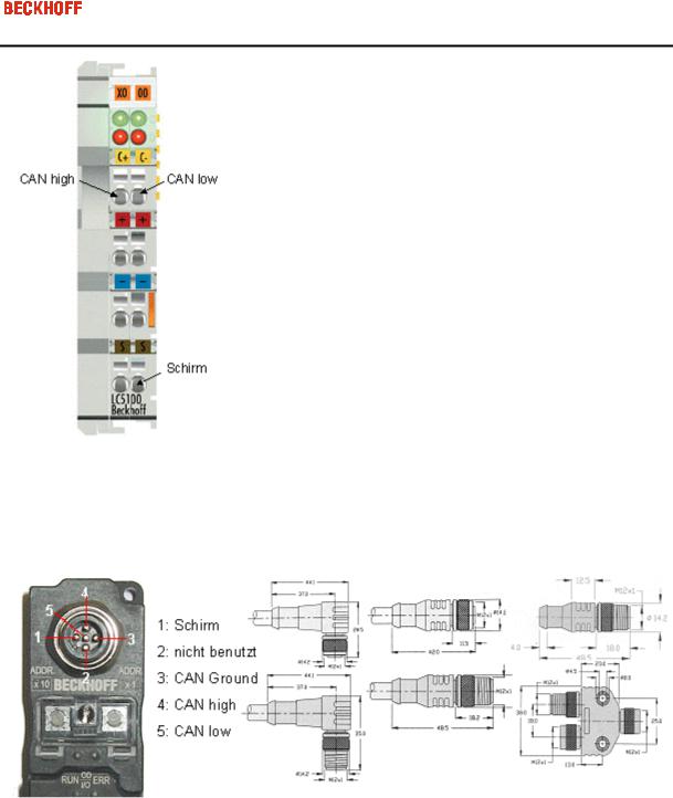
LC5100: Bus connection via spring-loaded terminals
In the low cost LC5100 coupler, the CAN wires are connected directly to the contact points 1 (CAN-H, marked with C+) and 5 (CAN-L, marked with C-). The screen can optionally be connected to contact points 4 or 8, which are connected to the mounting rail via an R/C network.
Eiserstraße 5 / D-33415 Verl / Telefon 05246/963-0 / Telefax 05246/963-149
19
Fieldbus Box: M 12 CAN socket
The IPxxxx-B510, IL230x-B510 and IL230x-C510 Fieldbus Boxes are connected to the bus using 5- pin M 12 plug-in connectors.
Beckhoff offer plugs for field assembly, passive distributor's, terminating resistors and a wide range of preassembled cables for the Fieldbus Box system. Details be found in the catalog, or under www.beckhoff.de
Eiserstraße 5 / D-33415 Verl / Telefon 05246/963-0 / Telefax 05246/963-149
20
4. Parameterisation and Commissioning
TwinCAT System Manager
The TwinCAT System Manager Tool is used to configure the FC510x CANopen PCI card. The System Manager provides a representation of the number of programs of the TwinCat PLC systems, the configuration of the axis control and of the connected I/O channels as a structure, and organises the mapping of the data traffic.
For applications without TwinCAT PLC or NC, the TwinCAT System Manager Tool configures the programming interfaces for a wide range of application programs:
ActiveX control (ADS-OCX) for e.g. Visual Basic, Visual C++, Delphi, etc.
DLL interface (ADS-DLL) for e.g. Visual C++ projects
Script interface (ADS script DLL) for e.g. VBScript, JScript, etc.
System Manager – Features
-Bit-wise association of server process images and I/O channels
-Standard data formats such as arrays and structures
-User defined data formats
-Continuous variable linking
-Drag and Drop
-Import and export at all levels
Configuration by means of the TwinCAT System Manager
The procedure, and the configuration facilities in the System Manager are described below.
Eiserstraße 5 / D-33415 Verl / Telefon 05246/963-0 / Telefax 05246/963-149
21
Context menu
Append Box... <Insert>
Adds CANopen slaves (boxes). Currently supports the following boxes (further details on the boxes given later):
Supported boxes |
Description |
|
|
BK5100 |
Bus Coupler |
BK5110 |
Economy Bus Couplers |
BK5120 |
Bus Coupler (successor of BK5100) |
|
|
LC5100 |
Low-cost Bus Couplers |
IPxxxx-B510 |
Fieldbus compact box: CANopen in/output module, protection class IP67 |
CANopen Node |
General CANopen device or general CAN device (access via CAN layer 2) |
Delete Device... <Del>
Removes the FC510x fieldbus card and all subsidiary elements from the I/O configuration.
Online Reset
Initiates an online reset on the CANopen bus.
Eiserstraße 5 / D-33415 Verl / Telefon 05246/963-0 / Telefax 05246/963-149
22
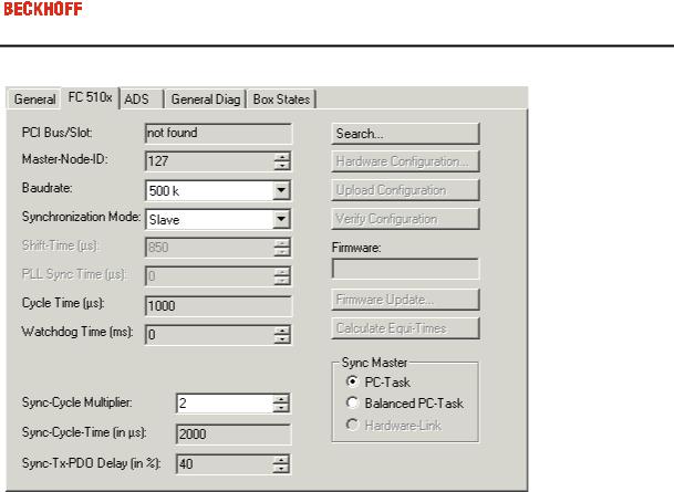
"FC510x" tab
PCI Slot/Irq:
Shows in which logical PCI slot the card was detected and which IRQ is assigned to it. The IRQ is unused.
Master Node Id:
Node address for the FC510x. Value range: 1...127. Determines the identifier of the master heartbeat telegram. Ensure that it is not the same as a slave node address.
Baud rate:
Set the Baud rate here. Automatically tests whether the connected slave also supports this baud rate.
Synchronization Mode:
The synchronization mode determines the accuracy of the CANopen SYNC telegram generation.
The highest priority task linked with the FC510x device controls the CANopen card and is thereby synchronized with the fieldbus. All other tasks are served asynchronously via corresponding buffers. For all operating modes you can individually set the communication type for each process data object (PDO) - event driven or synchronized (in each PDO tab). If one of the PDOs has been configured for synchronous operating mode, a SYNC telegram is sent at the start of the cycle, which the slaves use to synchronize their actions with the master cycle.
Depending on the sync accuracy requirements of the application several modes can be selected. Please note, that due to CAN technology a single SYNC telegram may jitter for one entire frame length it the bus is busy at the time of sync generation. The SYNC accuracy therefore refers to the long time stability. Bus nodes that use a phase locked loop (PLL) mechanism to synchronize themselves require a maximum long time stability or accuracy of the SYNC.
Eiserstraße 5 / D-33415 Verl / Telefon 05246/963-0 / Telefax 05246/963-149
23
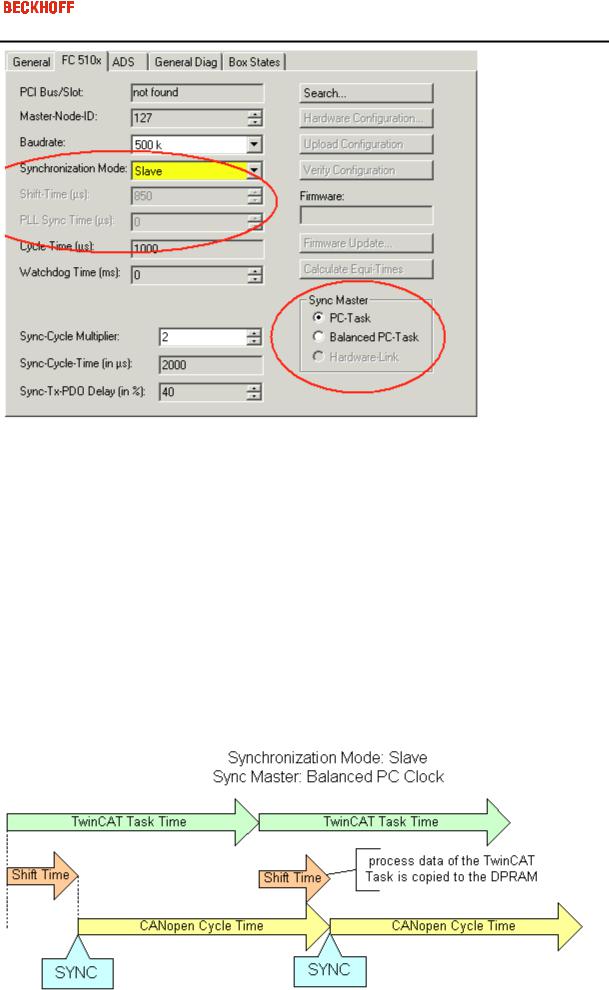
Slave
In slave synchronization mode the card receives its time basis from a sync master. The sync master is selected at the corresponding field.
Sync Master: PC-Task. This is the default setting. The PC provides the time basis using the TwinCAT Real Time. Depending on the settings the Task start (Default with TwinCAT NC) or the Task end (Default at TwinCAT PLC) triggers the SYNC telegram.
Sync Master: Balanced PC Task. This operating mode as well generated the CANopen Sync cycle with the long term accuracy of the PC time basis. However, the short term accuracy (interval between two SYNC telegrams) is better that with Sync Master "PC-Task":
-Run time differences (e.g. caused by case dependent program calls) are leveled out,
-the FC510x delays pending transmit telegrams until the SYNC telegram was sent,
-the SYNC intervals are determined by the quartz timer of the FC510x card.
The card timer is adjusted in small steps to the PC-timer if the difference is larger that the value of the "PLL Sync Time".
In this mode the SYNC telegram is delayed for the Shift Time after the end of the TwinCAT task cycle. Here the shift time should be set to a value as small as possible - but large enough to allow the process data access by the TwinCAT task. The function "Calculate Equi-Times" helps to configure the optimal shift time. It is started by selecting the corresponding button.
Eiserstraße 5 / D-33415 Verl / Telefon 05246/963-0 / Telefax 05246/963-149
24
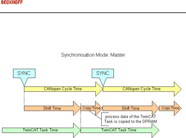
Master
In master synchronization mode the card generates its time basis locally. The SYNC is generated with long time quartz accuracy. The start of the TwinCAT task is triggered by the card, delayed by the Shift Time. In this mode the shift time value should be as large as possible. The function "Calculate Equi-Times" helps to configure the optimal shift time. It is started by selecting the corresponding button.
Cycle Time:
Displays the cycle time of the corresponding highest priority task. The value is updated when the TwinCAT mapping is generated.
Sync-Cycle Multiplier:
CANopen SYNC Cycle Time = (Task) Cycle Time x Sync-Cycle Multiplier. Event driven PDO communications and cyclic synchronized PDO communication are frequently combined when used in conjunction with CANopen. In order to be able to respond rapidly to an event, the TwinCAT task cycle time has to be less than the CANopen SYNC cycle time.
Sync-Cycle time
Shows the cycle time of the CANopen SYNC telegram. This cycle time is derived from the highest priority task which has process data linked to the card, and the Sync Cycle Multiplier.
Sync-Tx-PDO Delay:
Directly after the SYNC telegram, the synchronized slaves send their input data/actual values. The FC510x can delay the sending of the output data / set value (TxPDOs from the perspective of the card) in order to minimize the telegram burst directly after the SYNC. The Sync-Tx-PDO delay parameter is used to set this delay in percent of the Sync Cycle Time.
Example:
Eiserstraße 5 / D-33415 Verl / Telefon 05246/963-0 / Telefax 05246/963-149
25
Task Cycle Time = 2000µs, Sync Cycle Multiplier = 5, Sync Tx-PDO Delay =40[%]. Event driven PDOs can be processed by the PLC task every 2 ms. The CANopen sync cycle is 10 ms, the FC510x sends its synchronized PDOs 4ms (=40% of 10ms) after SYNC.
Search...:
Searches for all connected FC510x channels. Select those required. In the case of an FC5102 both channels A and B appear. These behave in logical terms like two FC5101 cards.
Hardware Configuration …:
In which the address of the FC510x is set in the lower memory area (below 1 MB) of the PC.
Upload Configuration:
Scans the CANopen network and adds all detected equipment to the device (FC510x) (only available when no box has been configured). In the case of Beckhoff boxes, reads the configuration precisely. In the case of external devices, the PDO configuration and the identity object are read and evaluated.
Verify Configuration:
Allows one to compare the expected (configured) network configuration with the actual (physically present) configuration. The data from the CANopen Identity object is read an compared. In the case of Beckhoff Boxes the connected Bus Terminals or Extension Modules are identified ad compared. In preparation.
Firmware:
Shows the current firmware version of the FC510x.
Firmware Update...:
Update the FC510x card firmware version here. Warning: The TwinCAT System must be stopped for this function.
”ADS” tab
The FC510x is an ADS device with its own net ID, which can be changed here. All ADS services (diagnosis, non-cyclical communication) going to the FC510x must address this net ID.
Eiserstraße 5 / D-33415 Verl / Telefon 05246/963-0 / Telefax 05246/963-149
26
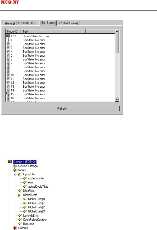
”Box States” tab
Displays an overview of all current box statuses.
Tab ”(Online) DPRAM”
See ”Online Display of DPRAM" in the System Manager Documentation.
Input Diagnosis
The FC510x automatically provides various diagnostic variables which describe the status of the card and the CANopen network:
cycleCounter: Is incremented at the end of each firmware cycle in order that this variable can indicate whether the last cycle was completed before the task was started.
Error: Shows the number of slaves whose Box State is not equal to zero. Only check the BoxState of the slaves if this value is other than 0.

Eiserstraße 5 / D-33415 Verl / Telefon 05246/963-0 / Telefax 05246/963-149
27
ActualCycleTime: Shows the current cycle time in 4/25 µs. This variable is only updated when all slaves are involved in the data exchange (and when error is 0)
DiagFlag: Shows whether the diagnostics information on the card has changed. This can be read off using ADS Read. For that purpose, specify the net ID of the FC510x, the port number 200 and the IndexGroup 0xF100. The IndexOffset and the length then relate to the diagnostic data. (Note: The Box States are also available as box variables.)
Offset 1-127: BusStatus List, 1-127 one byte per station address which contains the station status (see BoxState for CANopenboxes)
Global State: Various diagnostic and status displays for the FC510x. The byte in GlobalState(0) shows the status of the card in relation to the TwinCAT system: RUN, RESET, OFFLINE and STOP are distinguished. GlobalState(2) gives information about the status of the CAN controller: "CAN Warning Limit Reached" and "Bus Off" are displayed. Warning limit reached means that the send/receive error counter on the CAN controller has exceeded the value 96. BusOff means that the CAN controller can no longer participate in bus communication; this is caused by an excessive number of CAN errors (Error Frames). In this case there is a serious physical error in the CAN network. (e.g. too little or too much matching resistors, at least a device with an incorrect baudrate, short circuit etc.) The bus off state is only left by a card reset. Details about further global state data, see comments in ”Online” tab.
LastAdsError: Shows the error code of the last ADS access error, e.g. if an attempt has been made to read the diagnostic data for a deactivated node.
CycleFailedCounter: Counts the number of firmware cycles which could not be completed before the associated task wanted to re-read/re-write the process image. If this counter is incremented, the task cycle time has been set too low for the actual network configuration.
BusLoad: Shows the current bus load in %. The Bus Load is an important design criterion for CAN networks. The value shown is a average value over 100ms.
Eiserstraße 5 / D-33415 Verl / Telefon 05246/963-0 / Telefax 05246/963-149
28
BK51x0/LC5100/IPxxxx-B510 (CANopen)
The BK51x0 Bus Coupler and the IPxxx-B510 fieldbus box are installed in the CANopen bus. Those specific properties which distinguish them from other Bus Couplers and/or Fieldbus Box modules are described below. Following Bus Couplers are currently supported by TwinCAT:
Types |
Description |
BK5100 |
Bus Coupler |
BK5110 |
Economy Buskoppler |
|
|
BK5120 |
Bus Coupler, successor of BK5100 |
LC5100 |
Low-cost Bus Coupler |
IPxxxx-B510 |
Fieldbus Compact Box: CANopen in/output module, protection class IP67 |
ILxxxx-B510 |
Fieldbus Coupler Box: Expandable CANopen in/output module, protection class IP67 |
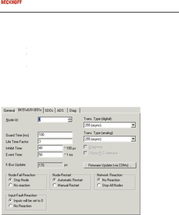
"BK51x0/IX-B510" tab
Node Id: Sets the node ID of the CAN bus device (between 1 and 63 (BK51x0) and/or 1 and 99 (IPxxxx-B510)). This value must comply with the value set at the Bus Coupler and/or at the compact box.
Guard time: Cycle time for the node monitoring (node guarding).
Life time factor: Guard time multiplied produces the watchdog time for the monitoring of the master by the coupler (life guarding). Life guarding is deactivated if the lifetime factor is set to zero.
Inhibit time: Displays the minimum send interval for PDOs (telegrams) with analogue and special signals. If more than digital 64 signals are present, these are also provided with this Inhibit Time.
Event Time: Sets the Event Timer Value for Transmit PDOs. The expiration of this timer is regarded as additional event for the corresponding PDO. Thus the PDO is being sent. If the application event occurs during the event timer period the PDO is sent as well and the timer is reset.
K-Bus Update: Calculates the anticipated duration of a complete update of the terminal bus (according to type and number of connected terminals).
Trans.Type: Gives the Transmission Type for digital / analogue input telegrams. 254 + 255 corresponds to the event-driven transfer, 1 … 240 are synchronous transfer types. For further details see also BK51X0 manual.
Eiserstraße 5 / D-33415 Verl / Telefon 05246/963-0 / Telefax 05246/963-149
29
Firmware Update: Enables the updating of the coupler firmware via the serial interface (requires KS2000 software package interface cable).
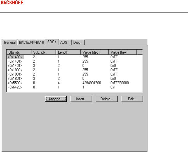
”SDOs” tab
SDO inputs sent to the node at StartUp are displayed/managed on this page. Inputs with an object index in straight brackets are automatically created on the basis of the updated terminal configuration. Other inputs can be managed using ”Add”, ”Insert”, ”Delete” and ”Edit”.
”ADS” tab
In order to be able to read and write SDO objects during the running time (e.g. from the PLC), the node (Bus Coupler) can be allocated an ADS port (CIFx0-CAN). The FC510x provides an ADS port at all times for every node since the diagnostic information is transported via ADS. These ports can be used to read and write SDO objects using ADS read requests and/or write requests.
The ADS IndexGroup contains the CANopen object index and the ADS IndexOffset contains the CANopen SubIndex. For details see Chapter SDO Communication
"Diag" tab
The diag tab displays the diagnosics information. The window contents are not refreshed cyclically. If required dial the "Refresh" button. The represented diagnosis information can be also questioned by ADS.
 Loading...