


Hardware documentation
for CX90x0 Ethernet controller
CX900x-xxxx
CX901x-xxxx
CX90x0-Nxxx
version:2.4 date:2008-06-11

Table of contents
Table of contents
1. Foreword |
|
Notes on the documentation |
|
Safety instructions |
4 |
Documentation issue status |
6 |
2. Product overview |
7 |
Appropiate use |
7 |
System overview |
8 |
Basic modules |
9 |
Technical data |
9 |
CX900x-0xxx (E-bus) |
10 |
CX900x-1xxx (K-bus) |
11 |
CX9010-0xxx (E-bus) |
12 |
CX9010-1xxx (K-bus) |
13 |
Configurations CX9000 |
14 |
Configurations CX9010 |
15 |
Connections |
16 |
Battery compartment |
20 |
DIP switch settings |
21 |
System interfaces |
24 |
Technical data |
24 |
Connections CX9000-N010 |
25 |
Connections CX9000-N030 |
27 |
Connections CX9000-N031 |
28 |
3. |
Transport |
31 |
|
Unpacking, installation and transport |
31 |
4. |
Assembly and connecting |
32 |
|
Mechanical assembly |
32 |
|
Dimensions |
32 |
|
Mechanical assembly of basic module |
35 |
|
Mechanical assembly of UPS module |
37 |
|
Start-up procedure |
40 |
|
Start-up procedure |
40 |
5. |
Error handling and diagnostics |
41 |
|
CPU basic module |
41 |
|
LED basic module E-Bus |
41 |
|
LED basic module K-Bus |
42 |
|
K-Bus diagnosis with TwinCAT |
44 |
6. |
Decomissioning |
46 |
|
Removal and disposal |
46 |
Embedded PC

Table of contents
7. Appendix |
48 |
Update image |
48 |
Accessories |
57 |
Certifications |
58 |
Support and service |
59 |
2 |
Embedded PC |

Foreword
1. Foreword
Notes on the Documentation
This description is only intended for the use of trained specialists in control and automation engineering who are familiar with the applicable national standards. It is essential that the following notes and explanations are followed when installing and commissioning these components.
Liability Conditions
The responsible staff must ensure that the application or use of the products described satisfy all the requirements for safety, including all the relevant laws, regulations, guidelines and standards.
The documentation has been prepared with care. The products described are, however, constantly under development. For that reason the documentation is not in every case checked for consistency with performance data, standards or other characteristics. None of the statements of this manual represents a guarantee (Garantie) in the meaning of § 443 BGB of the German Civil Code or a statement about the contractually expected fitness for a particular purpose in the meaning of § 434 par. 1 sentence 1 BGB. In the event that it contains technical or editorial errors, we retain the right to make alterations at any time and without warning. No claims for the modification of products that have already been supplied may be made on the basis of the data, diagrams and descriptions in this documentation.
© This documentation is copyrighted. Any reproduction or third party use of this publication, whether in whole or in part, without the written permission of Beckhoff Automation GmbH, is forbidden.
Embedded PC |
3 |
Foreword
Safety Instructions
Safety Rules
The responsible staff must ensure that the application or use of the products described satisfy all the requirements for safety, including all the relevant laws, regulations, guidelines and standards.
State at Delivery
All the components are supplied in particular hardware and software configurations appropriate for the application. Modifications to hardware or software configurations other than those described in the documentation are not permitted, and nullify the liability of Beckhoff Automation GmbH.
Personnel Qualification
This description is only intended for the use of trained specialists in control and automation engineering who are familiar with the applicable national standards.
Description of safety symbols
The following safety symbols are used in this operating manual. They are intended to alert the reader to the associated safety instructions
Danger
This symbol is intended to highlight risks for the life or health of personnel.
Warning
This symbol is intended to highlight risks for equipment, materials or the environment.
Note
This symbol indicates information that contributes to better understanding.
Operator's obligation to exercise diligence
The operator must ensure that
·the product is only used for its intended purpose.
·the product is only operated in sound condition and in working order.
·the instruction manual is in good condition and complete, and always available for reference at the location where the products are used.
·the product is operated only by suitably qualified and authorised personnel.
·the personnel is instructed regularly about relevant occupational safety and environmental protection aspects, and is familiar with the operating manual and in particular the safety notes contained herein.
National regulations depending on the machine type
Depending on the type of machine and plant in which the product is used, national regulations governing the controllers of such machines will apply, and must be observed by the operator. These regulations cover, amongst
4 |
Embedded PC |

Foreword
other things, the intervals between inspections of the controller. The operator must initiate such inspections in good time.
Operator requirements
Read the operating instructions
All users of the product must have read the operating instructions for the system they work with.
System know-how
All users must be familiar with all accessible functions of the product.
Embedded PC |
5 |
Foreword
Documentation Issue Status
Version  Changes
2.4system interfaces CX1200-xxxx removed
2.3 new installation positions are added
2.2 changes in names of system interfaces CX90x0-N070 and CX90x0-N080 inserted
2.1notes on new system interfaces CX90x0-N070 and CX90x0-N080 added
2.0 notes on UL added
1.9order information changed
1.8notes on K-Bus diagnosis added
1.7notes on USV and CF card handling added title picture changed
1.6 Notes on software image update
1.5 cable length for DVI cable corrected
1.4consumption value for CX1020-A001 added
1.3notes on dip switches and image update added
1.2information for CF-cards changed, errors in product numbers corrected
1.1notes for system interface N010 added
1.0revised version
0.0.1 |
preliminarily version |
6 |
Embedded PC |
Product overview
2. Product overview
Appropriate Use
The CX-SYSTEM device series is a modular control system designed for top-hat rail installation. The system is scalable, so that the required modules can be assembled and installed in the control cabinet or terminal box as required.
Only switch the PC off after closing the software
Before the Embedded PC is switched off, the software currently running on it should be stopped properly in order to avoid data loss on the hard disk. Please read the section on “Switching off”.
Switch off all system components and uncouple the Industrial PC from the system if the PC is not used for control purposes, e.g. during a function test.
System components that have been switched off must be secured against being switched on again.
The power supply unit of the Embedded PC requires a 24 V DC supply.
Danger
Do not exchange any parts when under power!
When components are being fitted or removed, the supply voltage must be switched off.
Software knowledge
Warning
Mandatory software knowledge!
Every user must be familiar with any of the functions of the software installed on the PC that he can reach.
Embedded PC |
7 |
Product overview
System overview
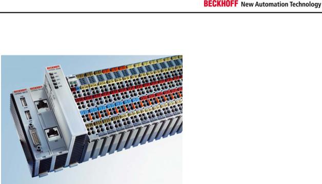
Ethernet-Controller CX9000
With the Ethernet controller CX9000, Beckhoff presents a further extension of the family of CX-type embedded controllers. The CX9000 is a compact, high-performance yet cost-effective PLC and motion controller for 30 mm DIN rail mounting. Within the Beckhoff control world it is positioned between the Bus Terminal Controller series BX and the Embedded PC CX1000. The main feature of this devices is an energy-saving 266 MHz Intel® IXP420 CPU with XScale® technology that runs under the Microsoft Windows CE operating system. It thus offers adequate computing capacity even for complex automation tasks. The CX9000 requires no external storage media – the device boots the operating system from the internal fl ash. Due to the low power consumption, within the specified operating range no fan is required. The CX9000 therefore requires no rotating components. As usual for the CX series, the device features a modular mechanical design. In its basic configuration, the compact device only measures 58 x 100 x 91 mm.
EtherCAT as fast I/O-System / K-Bus as alternative I/O-System
The CX9000 is available in two versions: with K-bus for direct connection of Bus Terminals, and as an E-bus version for direct connection of EtherCAT Terminals. In the basic confi guration, two RJ 45 sockets that are internally connected to an integrated switch are available as interfaces. This simplifies wiring of several CX9000 within a line topology. No separate switch hardware is required. The two externally accessible Ethernet ports are independent of the EtherCAT interface, which is served by a second MAC (media access controller) provided by the CPU.
Basic module and Systeminterfaces
Further interfaces may be added ex works as required: A screen display can be realized using a CX9000-N001 device, i.e. a module combining DVI/ VGA + 2 x USB 2.0. The combination of DVI and USB enables all types of Beckhoff Control Panel with DVI/USB interface to be used. Touch functionality is connected via USB. As a further option, two RS232 modules or two RS422/RS485 modules can be configured as COM1 and COM2. All serial interfaces feature opto-decoupling. Mass storage in form of a Compact Flash card can be used via the CX9000-A000 module, which offers physical storage capacity in the range of several gigabytes.
SPS, Motion Control and Visualization
Like for all Beckhoff controllers, TwinCAT is used for programming the CX9000 as an automation device. The device itself contains the run-time environment for PLC and Motion Control. One of the two Ethernet interfaces is used as programming interface.
Software
Microsoft Windows CE enables the creation of fully graphic user programs,which are able to satisfy high expectationsthanks to the graphics chip integrated in the CX9000.
In summary, the CX9000 is a compact Ethernet controller, which in combination with EtherCAT I/O allows very fast I/O control cycles. Windows CE and TwinCAT CE constitute the powerful software architecture for this controller.
8 |
Embedded PC |
Product overview
Basic modules
Ethernet-Controller CX90x0
The CX9000 is a compact, top hat rail-mountable Ethernet Controller with direct connection to the Beckhoff I/O systems in IP 20. The CX90x0 is available in four basic versions: two version for Bus Terminals with K-bus, the other two for EtherCAT Terminals with E-bus. The CX90x0 comprises the CPU (available in 266 MHz and 533 MHz), the internal flash memory with two configuration options, the main memory (RAM) (available in two different sizes), and NOVRAM as non-volatile memory. Two Ethernet RJ 45 interfaces are also part of the basic configuration. These interfaces are connected to an internal switch and offer a simple option for creating a line topology without the need for additional Ethernet switches. A memory medium in Compact Flash format I and II is available as an optional module.(only in combination with system interface CX90x0-N010) The operating system is Microsoft Windows CE. The TwinCAT automation software transforms a CX90x0 system into powerful PLC and Motion Control system that can be operated with or without visualization. Further system interfaces can be connected to the CPU module ex works. The CX9000-N010 option can be connected to Beckhoff Control Panels or standard monitors with DVI or VGA input via the DVI and USB interfaces. Devices such as printer, scanner, mouse, keyboard, mass storage, CR-RW etc. can be connected via the USB2.0 interfaces. The module CX90x0-N030 offers two serial RS232 interfaces with a maximum transfer speed of 115 kbaud. These two interfaces can be implemented as RS422/RS485, in which case they are identified as CX90x0-N031.
The Ethernet-Controller CX90xx is offered in four versions:
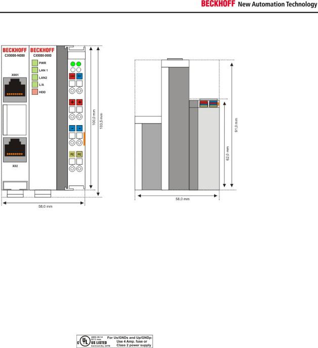
•CX900x-0000 E-bus connection
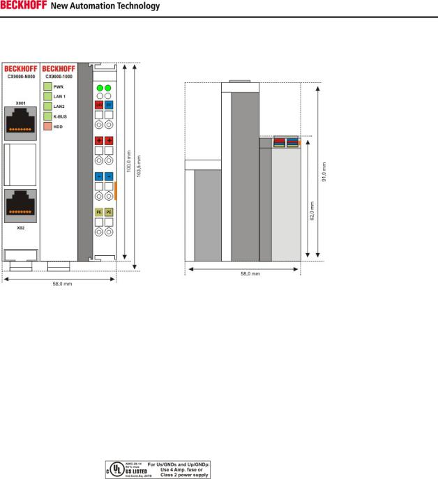
•CX900x-1000 K-bus connection
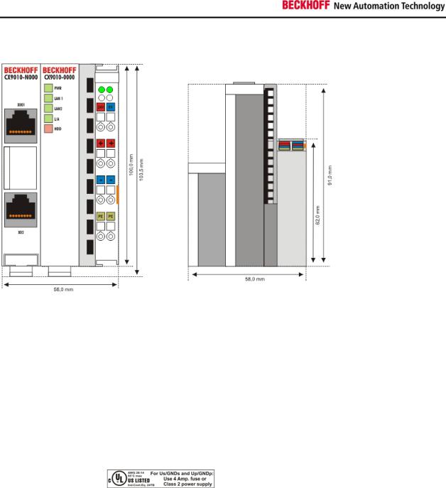
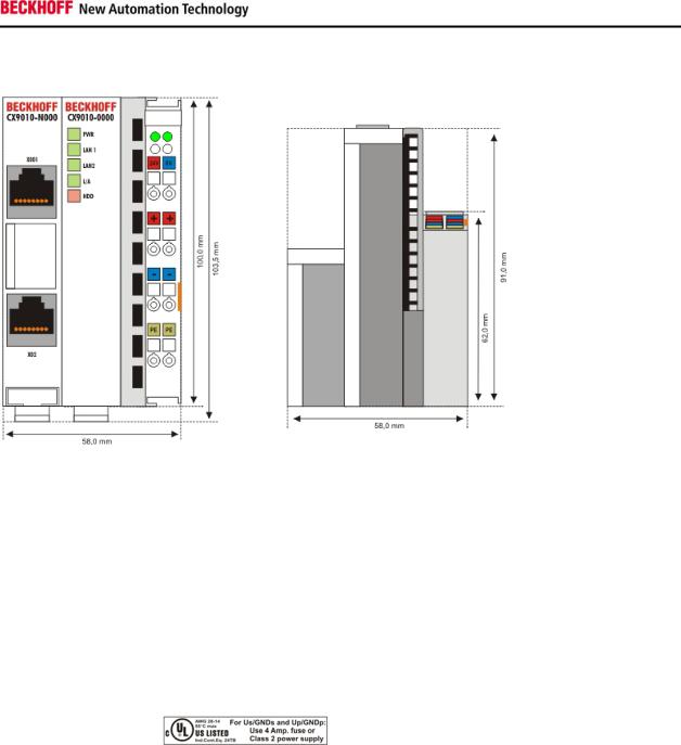
•CX9010-0000 E-bus connection
•CX9010-1000 K-bus connection
Embedded PC |
9 |
Product overview
Technical data – CX9000-0000 E-bus connection
Technical data |
CX9000-0000 |
|
|
Processor |
Intel® IXP420 with Xscale® Technology, 266-MHz clock rate |
Internal flash memory |
16 Mbyte Flash (internal, expandable up to 32 Mbyte) |
|
|
Internal main memory |
64 Mbyte RAM (internal, expandable up to 128 Mbyte) |
interfaces |
2 x RJ 45 (internal Switch), 10/100 Mbit |
Diagnostics LEDs |
1 x Power, 2 x LAN, 1 x L/A, 1 x flash access |
|
|
Clock |
internal battery-backed clock for time and date |
Operating system |
Microsoft Windows CE |
|
|
Control software |
TwinCAT-CE-PLC-Runtime or TwinCAT-CE-NC-PTP-Runtime |
Power supply |
24 VDC (-15%/+20%) To meet the UL requirements use a 4 A fuse or a power |
|
supply that has to satisfy NEC class 2! |
|
|
Dielectric strength |
500 Vrms (supply/internal electronics) |
I/O connection |
E-bus (EtherCAT Terminals) |
|
|
NOVRAM |
128 kByte |
I/O-DPRAM |
- |
|
|
Power supply I/O |
2 A |
terminals |
|
Max. power loss |
6 W (including CX9000-xxxx system interfaces) |
|
|
Dimensions (W x H x D) |
59 mm x 100 mm x 91 mm |
weight |
ca. 250 g |
|
|
Operating / storage |
0° C ... +50° C / -25° C ... +85° C |
temperature |
|
Relative humidity |
95% no condensation |
Vibration/shock |
conforms to EN 60068-2-6 / EN 60068-2-27/29 |
resistance |
|
EMC resistance |
conforms to EN 61000-6-2/EN 61000-6-4 |
burst/ESD |
|
Protection class |
IP 20 |
10 |
Embedded PC |
Product overview
Technical data CX9000-1000 K-bus connection
Technical data |
CX9000-1000 |
|
|
Processor |
Intel® IXP420 with XScale® Technology, 266-MHz clock rate |
Internal flash memory |
16 MByte Flash (internal, expandable up to 32 MByte) |
|
|
Internal main memory |
64 MByte RAM (internal, expandable up to 128 MByte) |
interfaces |
2 x RJ 45 (internal Switch), 10/100 MBit |
Diagnostics LEDs |
1 x Power, 2 x LAN, 1 x K-Bus, 1 x Flash-Zugriff |
|
|
Clock |
internal battery-backed clock for time and date |
Operating system |
Microsoft Windows CE |
|
|
Control software |
TwinCAT-CE-PLC-Runtime or TwinCAT-CE-NC-PTP-Runtime |
Power supply |
24 VDC (-15%/+20%) To meet the UL requirements use a 4 A fuse or a power |
|
supply that has to satisfy NEC class 2! |
|
|
Dielectric strength |
500 Vrms (supply/internal electronics) |
I/O connection |
K-bus (Bus Terminals) |
|
|
NOVRAM |
128 kByte |
I/O-DPRAM |
4 kByte |
|
|
Power supply I/O |
2 A |
terminals |
|
Max. power loss |
6 W (including CX9000-xxxx system interfaces) |
|
|
Dimensions (W x H x D) |
59 mm x 100 mm x 91 mm |
weight |
ca. 250 g |
|
|
Operating / storage |
0° C ... +50° C / -25° C ... +85° C |
temperature |
|
Relative humidity |
95% no condensation |
|
|
Vibration/shock |
conforms to EN 60068-2-6 / EN 60068-2-27/29 |
resistance |
|
EMC resistance |
conforms to EN 61000-6-2/EN 61000-6-4 |
burst/ESD |
|
Protection class |
IP 20 |
Embedded PC |
11 |
Product overview
Technical data – CX9010-0000 E-bus connection
Technical data |
CX9010-0000 |
|
|
Processor |
Intel® IXP420 with Xscale® Technology, 533-MHz clock rate |
Internal flash memory |
32 Mbyte Flash (internal) |
|
|
Internal main memory |
128 Mbyte RAM (internal) |
interfaces |
2 x RJ 45 (internal Switch), 10/100 Mbit |
Diagnostics LEDs |
1 x Power, 2 x LAN, 1 x L/A, 1 x flash access |
|
|
Clock |
internal battery-backed clock for time and date |
Operating system |
Microsoft Windows CE |
|
|
Control software |
TwinCAT-CE-PLC-Runtime or TwinCAT-CE-NC-PTP-Runtime |
Power supply |
24 VDC (-15%/+20%) To meet the UL requirements use a 4 A fuse or a power |
|
supply that has to satisfy NEC class 2! |
|
|
Dielectric strength |
500 Vrms (supply/internal electronics) |
I/O connection |
E-bus (EtherCAT Terminals) |
|
|
NOVRAM |
128 kByte |
I/O-DPRAM |
- |
|
|
Power supply I/O |
2 A |
terminals |
|
Max. power loss |
7 W (including CX9000-xxxx system interfaces) |
|
|
Dimensions (W x H x D) |
59 mm x 100 mm x 91 mm |
weight |
ca. 250 g |
|
|
Operating / storage |
0° C ... +50° C / -25° C ... +85° C |
temperature |
|
Relative humidity |
95% no condensation |
|
|
Vibration/shock |
conforms to EN 60068-2-6 / EN 60068-2-27/29 |
resistance |
|
EMC resistance |
conforms to EN 61000-6-2/EN 61000-6-4 |
burst/ESD |
|
Protection class |
IP 20 |
12 |
Embedded PC |
Product overview
Technical data CX9010-1000 K-bus connection
Technical data |
CX9010-1000 |
|
|
Processor |
Intel® IXP420 with XScale® Technology, 533-MHz clock rate |
Internal flash memory |
32 MByte Flash (internal) |
|
|
Internal main memory |
128 MByte RAM (internal) |
interfaces |
2 x RJ 45 (internal Switch), 10/100 MBit |
Diagnostics LEDs |
1 x Power, 2 x LAN, 1 x K-Bus, 1 x Flash-Zugriff |
|
|
Clock |
internal battery-backed clock for time and date |
Operating system |
Microsoft Windows CE |
|
|
Control software |
TwinCAT-CE-PLC-Runtime or TwinCAT-CE-NC-PTP-Runtime |
Power supply |
24 VDC (-15%/+20%) To meet the UL requirements use a 4 A fuse or a power |
|
supply that has to satisfy NEC class 2! |
|
|
Dielectric strength |
500 Vrms (supply/internal electronics) |
I/O connection |
K-bus (Bus Terminals) |
|
|
NOVRAM |
128 kByte |
I/O-DPRAM |
4 kByte |
|
|
Power supply I/O |
2 A |
terminals |
|
Max. power loss |
7 W (including CX90x0-xxxx system interfaces) |
|
|
Dimensions (W x H x D) |
59 mm x 100 mm x 91 mm |
weight |
ca. 250 g |
|
|
Operating / storage |
0° C ... +50° C / -25° C ... +85° C |
temperature |
|
Relative humidity |
95% no condensation |
|
|
Vibration/shock |
conforms to EN 60068-2-6 / EN 60068-2-27/29 |
resistance |
|
EMC resistance |
conforms to EN 61000-6-2/EN 61000-6-4 |
burst/ESD |
|
Protection class |
IP 20 |
Embedded PC |
13 |
Product overview
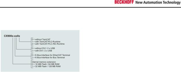
Configurations CX9000
The order identifier of the basic CPU module is derived as follows:
Following CX9000 configurations are available:
|
|
|
|
|
DVI, |
|
TwinCAT- |
TwinCAT- |
Ordering |
16 MB Flash |
32 MB Flash |
E- |
K- |
2 x |
no |
PLC- |
NC- |
information |
64 MB RAM |
128 MB RAM |
Bus |
Bus |
USB |
TwinCAT |
Runtime |
Runtime |
|
|
|
|
|
|
|
|
|
CX9000-0000 |
X |
- |
x |
- |
- |
X |
- |
- |
|
|
|
|
|
|
|
|
|
CX9000-0001 |
X |
- |
x |
- |
- |
- |
x |
- |
|
|
|
|
|
|
|
|
|
CX9000-1000 |
X |
- |
- |
x |
- |
x |
- |
- |
|
|
|
|
|
|
|
|
|
CX9000-1001 |
X |
- |
- |
x |
- |
- |
x |
- |
|
|
|
|
|
|
|
|
|
CX9001-0000 |
- |
x |
x |
- |
- |
x |
- |
- |
|
|
|
|
|
|
|
|
|
CX9001-0001 |
- |
x |
x |
- |
- |
- |
x |
- |
|
|
|
|
|
|
|
|
|
CX9001-0002 |
- |
x |
x |
- |
- |
- |
x |
x |
|
|
|
|
|
|
|
|
|
CX9001-0100 |
- |
x |
x |
- |
x |
x |
- |
- |
|
|
|
|
|
|
|
|
|
CX9001-0101 |
- |
x |
x |
- |
x |
- |
x |
- |
|
|
|
|
|
|
|
|
|
CX9001-0102 |
- |
x |
x |
- |
x |
- |
x |
x |
|
|
|
|
|
|
|
|
|
CX9001-1000 |
- |
x |
- |
x |
- |
x |
- |
- |
|
|
|
|
|
|
|
|
|
CX9001-1001 |
- |
x |
- |
x |
- |
- |
x |
- |
|
|
|
|
|
|
|
|
|
CX9001-1002 |
- |
x |
- |
x |
- |
- |
x |
x |
|
|
|
|
|
|
|
|
|
CX9001-1100 |
- |
x |
- |
x |
x |
x |
- |
- |
|
|
|
|
|
|
|
|
|
CX9001-1101 |
- |
x |
- |
x |
x |
- |
x |
- |
|
|
|
|
|
|
|
|
|
CX9001-1102 |
- |
x |
- |
x |
x |
- |
x |
x |
|
|
|
|
|
|
|
|
|
14 |
Embedded PC |
Product overview
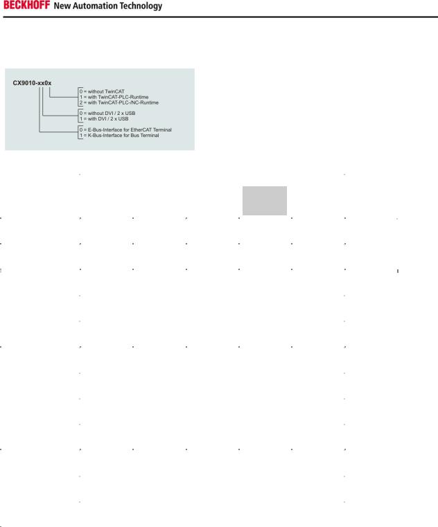
Configurations CX9010
The order identifier of the basic CPU module is derived as follows:
Following CX9000 configurations are available:
|
|
|
|
|
TwinCAT- |
TwinCAT- |
Ordering |
|
|
DVI, 2 x |
no |
PLC- |
NC- |
information |
E-Bus |
K-Bus |
USB |
TwinCAT |
Runtime |
Runtime |
|
|
|
|
|
|
|
CX9010-0000 |
x |
- |
- |
x |
- |
- |
|
|
|
|
|
|
|
|
|
|
|
|
|
|
CX9010-0001 |
x |
- |
- |
- |
x |
- |
|
|
|
|
|
|
|
|
|
|
|
|
|
|
CX9010-0002 |
x |
- |
- |
- |
x |
x |
|
|
|
|
|
|
|
|
|
|
|
|
|
|
CX9010-0100 |
x |
- |
x |
x |
- |
- |
|
|
|
|
|
|
|
|
|
|
|
|
|
|
CX9010-0101 |
x |
- |
x |
- |
x |
- |
|
|
|
|
|
|
|
|
|
|
|
|
|
|
CX9010-0102 |
x |
- |
x |
- |
x |
x |
|
|
|
|
|
|
|
|
|
|
|
|
|
|
CX9010-1000 |
- |
x |
- |
x |
- |
- |
|
|
|
|
|
|
|
|
|
|
|
|
|
|
CX9010-1001 |
- |
x |
- |
- |
x |
- |
|
|
|
|
|
|
|
|
|
|
|
|
|
|
CX9010-1002 |
- |
x |
- |
- |
x |
x |
|
|
|
|
|
|
|
|
|
|
|
|
|
|
CX9010-1100 |
- |
x |
x |
x |
- |
- |
|
|
|
|
|
|
|
|
|
|
|
|
|
|
CX9010-1101 |
- |
x |
x |
- |
x |
- |
|
|
|
|
|
|
|
|
|
|
|
|
|
|
CX9010-1102 |
- |
x |
x |
- |
x |
x |
|
|
|
|
|
|
|
|
|
|
|
|
|
|
Embedded PC |
15 |
Product overview
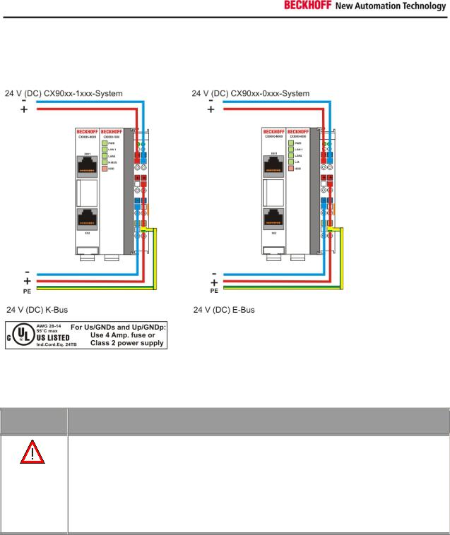
Connections
The system is supplied with power via the integrated power supply. This is wired as follows:
The basic module is powered via the upper connectors with 24 V DC. The terminal bus can be supplied via the lower connections.
UL requirements
Danger
For the compliance of the UL requirements the CX-Controllers should only be supplied
•by a 24 VDC supply voltage, supplied by an isolating source and protected by means of a fuse (in accordance with UL248), rated maximum 4 Amp.
•by a 24 VDC power source, that has to satisfy NEC class 2.
A NEC class 2 power supply shall not be connected in series or parallel with another (class 2) power source!
These UL requirements are valid for all supply voltages of the CX-Controllers!
16 |
Embedded PC |
Product overview
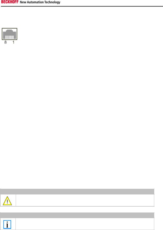
CPU basic module with 2 Ethernet RJ 45 connectors:
RJ 45 interface (socket):
Assignment of the RJ45-interface, Port 1:
|
PIN |
|
|
Signal |
|
|
|
Desciption |
|
|
|
|
|
|
|
|
|||
|
|
|
|
|
|
|
|
|
|
1 |
|
|
TD + |
|
|
Transmit + |
|||
|
|
|
|
|
|
|
|
|
|
2 |
|
|
TD - |
|
|
Transmit - |
|||
3 |
|
|
RD + |
|
|
Receive + |
|||
|
|
|
|
|
|
|
|
|
|
4 |
|
|
connected |
|
|
|
not used |
|
|
|
|
|
|
|
|
|
|
|
|
5 |
|
|
|
|
|
|
|
|
|
|
|
|
|
|
|
|
|
|
|
6 |
|
|
RD - |
|
|
Receive - |
|||
|
|
|
|
|
|
|
|||
7 |
|
|
connected |
|
|
|
not used |
|
|
|
|
|
|
|
|
|
|
|
|
8 |
|
|
|
|
|
|
|
|
|
|
|
|
|
|
|
|
|
|
|
TD & RD are exchanged at the hubs or between two PCs.
Assignment of the RJ45 interface, Port 2:
PIN |
Signal |
Description |
|
|
|
1 |
TD + |
Transmit + |
2 |
TD - |
Transmit - |
|
|
|
3 |
RD + |
Receive + |
4 |
connected |
not used |
|
|
|
5 |
|
|
|
|
|
6 |
RD - |
Receive - |
7 |
connected |
not used |
|
|
|
8 |
|
|
|
|
|
TD & RD are exchanged at the hubs or between two PCs.
Connection of the Ethernet ports:
Warning
The two Ethernet ports of a basic CPU module must not be connected to the same external switch!
Note
Only for use in LAN, not for connection to telecommunication circuits.
Schematic structure of the network components:
The CX9000 features two MAC blocks. The first one (MAC1) operates the network interfaces for the Ethernet ports. The two outputs are connected via a switch. In this way a line structure can be configured as described below. From an operating system perspective this represents a single connection. The second block (MAC2) operates the extended PC104 bus. The second physical network connection is used to run the E-bus connection. (in version CX900x-0xxx) The signals are connected to and FPGA. This unit converts the Ethernet signals to E-bus signals. So EtherCAT terminals can be connected to the system.
Embedded PC |
17 |
 Loading...