


 Loading...
Installation and Operating instructions for
Control Cabinet PCs C6920, C6925
Version: 2.2
Date: 2012-09-14

|
Table of contents |
|
|
Table of contents |
|
1. Foreword |
3 |
Notes on the Documentation |
3 |
Liability Conditions |
3 |
Trademarks |
3 |
Patent Pending |
3 |
Copyright |
3 |
State at Delivery |
3 |
Delivery conditions |
3 |
Description of safety symbols |
4 |
Basic safety measures |
5 |
Operator’s obligation to exercise diligence |
6 |
Operator requirements |
6 |
2. Product Description |
7 |
Appropriate Use |
7 |
Access to the battery and drives |
7 |
Status-LEDs |
8 |
Fan cartridge C6920 |
8 |
Extension for PCI and PCIe plug-in cards |
9 |
Access to the plug-in card slots |
9 |
Interfaces |
10 |
Power Supply |
10 |
Network connection |
10 |
USB-Interfaces |
10 |
DVI (Digital Visual Interface) |
10 |
Serial interface |
10 |
Fieldbus |
10 |
Additional plug-in cards (optional) |
10 |
3. Installation Instructions |
11 |
Transport and Unpacking |
11 |
Transport |
11 |
Unpacking |
11 |
Installation of the PC in the control cabinet |
12 |
Earthing measures |
12 |
Power Supply Connection |
13 |
Beckhoff power supply technology |
13 |
Pin assignment of the connector |
14 |
Fitting the cable |
15 |
Material for assembling the connectors |
15 |
Assembling the connectors |
15 |
Connecting Power Supply |
16 |
Cable Cross Sections |
16 |
Configuration for shutting down the PC |
16 |
PC_ON and Power Status functions |
16 |
UPS output |
16 |
UPS output function |
16 |
Wiring diagram |
17 |
Connecting devices |
18 |
Connecting cables |
18 |
Check voltage rating and connect |
18 |
4. Operating Instructions |
19 |
Switching the Industrial PC on and off |
19 |
First switching on and driver installation |
19 |
Servicing and Maintenance |
20 |
Cleaning the Industrial PC |
20 |
Servicing |
20 |
Replacing the battery on the motherboard |
20 |
Emergency procedures |
20 |
1 |
C6920/ 25 |

Table of contents
Shutting down |
20 |
Disposal |
20 |
5. UPS Software Components (optional) |
21 |
Installation on the PC |
21 |
Help files |
21 |
6. Troubleshooting |
22 |
Fault correction |
22 |
Beckhoff Support and Service |
23 |
Beckhoff branches and partner companies |
23 |
Beckhoff company headquarters |
23 |
Beckhoff Support |
23 |
Beckhoff Service |
23 |
7. Assembly dimensions |
24 |
Industrial-PC C6920 |
24 |
Industrial-PC C6920 |
25 |
Industrial-PC C6920 with plug-in card slots |
26 |
Industrial-PC C6920 with plug-in card slots |
27 |
Industrial-PC C6925 |
28 |
Industrial-PC C6925 |
29 |
8. Appendix |
30 |
Technical data |
30 |
Approvals |
30 |
FCC: Federal Communications Commission Radio Frequency Interference |
|
Statement |
30 |
FCC: Canadian Notice |
30 |
2 |
C6920/ 25 |

Foreword
Foreword
Notes on the Documentation
This description is only intended for the use of trained specialists in control and automation engineering who are familiar with the applicable national standards. It is essential that the following notes and explanations are followed when installing and commissioning these components.
The responsible staff must ensure that the application or use of the products described satisfy all the requirements for safety, including all the relevant laws, regulations, guidelines and standards.
Liability Conditions
The documentation has been prepared with care. The products described are, however, constantly under development. For that reason the documentation is not in every case checked for consistency with performance data, standards or other characteristics. In the event that it contains technical or editorial errors, we retain the right to make alterations at any time and without warning. No claims for the modification of products that have already been supplied may be made on the basis of the data, diagrams and descriptions in this documentation.
Trademarks
Beckhoff®, TwinCAT®, EtherCAT®, Safety over EtherCAT®, TwinSAFE® and XFC® are registered trademarks of and licensed by Beckhoff Automation GmbH.
Other designations used in this publication may be trademarks whose use by third parties for their own purposes could violate the rights of the owners.
Patent Pending
The EtherCAT Technology is covered, including but not limited to the following patent applications and patents:
EP1590927, EP1789857, DE102004044764, DE102007017835
with corresponding applications or registrations in various other countries. The TwinCAT Technology is covered, including but not limited to the following patent applications and patents:
EP0851348, US6167425 with corresponding applications or registrations in various other countries.
Copyright
© Beckhoff Automation GmbH.
The reproduction, distribution and utilization of this document as well as the communication of its contents to others without express authorization are prohibited. Offenders will be held liable for the payment of damages. All rights reserved in the event of the grant of a patent, utility model or design.
State at Delivery
All the components are supplied in particular hardware and software configurations appropriate for the application. Modifications to hardware or software configurations other than those described in the documentation are not permitted, and nullify the liability of Beckhoff Automation GmbH.
Delivery conditions
In addition, the general delivery conditions of the company Beckhoff
Automation GmbH apply.
C6920/ 25 |
3 |
Foreword
|
Description of safety symbols |
|
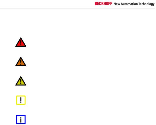
The following safety symbols are used in this operating manual. They are |
|
intended to alert the reader to the associated safety instructions. |
|
|
|
Acute risk of injury!! |
DANGER |
If you do not adhere the safety advise adjoining this symbol, there is |
immediate danger to life and health of individuals! |
|
|
|
|
Risk of injury! |
WARNING |
If you do not adhere the safety advise adjoining this symbol, there is |
danger to life and health of individuals! |
|
|
|
|
Hazard to individuals! |
CAUTION |
If you do not adhere the safety advise adjoining this symbol, there is |
obvious hazard to individuals! |
|
|
|
|
Hazard to devices and environment |
Attention |
If you do not adhere the notice adjoining this symbol, there is obvious |
hazard to materials and environment. |
|
|
|
|
Note or pointer |
Note |
This symbol indicates information that contributes to better understanding. |
|
4 |
C6920/ 25 |
Foreword
Basic safety measures
Only switch the PC off after closing the software
Before the Industrial PC is switched off, software that is running must be properly closed.
Otherwise it is possible that data on the hard disk is lost. Please read the section on Switching the Industrial PC on and off.
|
Switch off all parts of the equipment, then uncouple the fieldbus |
|
Before opening the housing of the PC, and whenever the PC is being |
Attention |
used for purposes other than plant control, such as during functional tests |
|
following repair, all parts of the equipment must first be switched off, after |
|
which the Industrial PC can be uncoupled from the plant. |
|
Pulling out the fieldbus connection plug uncouples the PC (optional). |
|
Items of equipment that have been switched off must be secured against |
|
being switched on again. |
|
The Industrial PC’s power supply unit must be supplied with 24 VDC. |
|
|
|
Do not exchange any parts when under power |
|
When components are being fitted or removed, the supply voltage must |
Attention |
be switched off. |
Fitting work on the Industrial PC can result in damage:
•if metal objects such as screws or tools fall onto operating circuit boards.
•if connecting cables internal to the PC are removed or inserted during operation.
•if plug-in cards are removed or inserted when the PC is switched on.
C6920/ 25 |
5 |
Foreword
Operator’s obligation to exercise diligence
The operator must ensure that
• the Industrial PC is only used for its intended use (see also Product Description chapter).
• the Industrial PC is in a sound condition and in working order during operation (see also chapter Servicing and Maintenance).
• the operation manual is in good condition and complete, and always available for reference at the location of the Industrial PC.
• the Industrial PC is operated, maintained and repaired only by sufficiently qualified and authorized personnel.
|
• the personnel is instructed regularly about relevant occupational |
|
safety and environmental protection aspects, and is familiar with |
|
the operating manual and in particular the safety notes contained |
|
herein. |
|
• none of the safety and warning notes attached to the Industrial PC |
|
are removed, and that all notes remain legible. |
National regulations |
Depending on the type of machine and plant in which the Industrial PC is |
depending on the machine |
being used, there will be national regulations for the control of such |
type |
machines and plant that the operator must observe. These regulations |
|
cover, amongst other things, the intervals between inspections of the |
|
controller. |
|
The operator must initiate such inspections in good time. |
|
|
|
Only trained persons may open the Industrial PC housing! |
Attention |
The operator is responsible for ensuring that only trained electrical staff |
opens the housing of the Industrial PC. |
Procedure in the event of a fault
In the event of a fault in the Industrial PC, appropriate measures can be determined with the aid of the list in the Fault correction section.
|
Operator requirements |
Read the operating |
Every user of the Industrial PC must have read these operating |
instructions |
instructions. |
Software knowledge |
Every user must be familiar with any of the functions of the software |
|
installed on the PC that he can reach. |
6 |
C6920/ 25 |
Product Description
Product Description
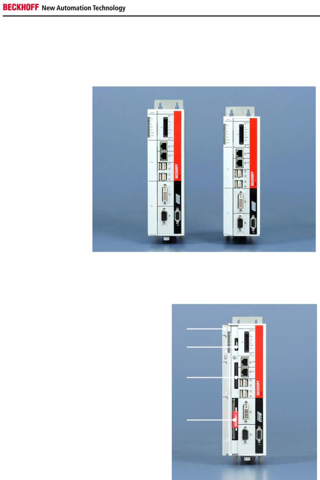
Appropriate Use
The C6920/ 25 series Industrial PCs are designed for mounting in control cabinets for machine and plant engineering applications.
Front view of Industrial PC |
C6920 |
C6925 |
|
C6920/ 25 |
|||
|
|
Configuration |
The C6920 is fitted with a fan cartridge with observated double ball bearing |
|
|
|
fans, exchangeable at the front. |
|
The C6925 is a fanless Industrial PC with passive cooling. |
|
Access to the battery and drives |
Access to hard-disk |
|
(optional), CF-Card/ |
|
CFast-Card and the battery |
1 |
|
|
|
2 |
|
3 |
4
Opening the front flap (1) allows access to the battery (2), the CF-Card/ CFast-Card (3) and the hard disk (4) (optional).
When provided with a CF-Card the ejection of the card occurs by pressing the eject button below the card slot.
C6920/ 25 |
7 |
Product Description
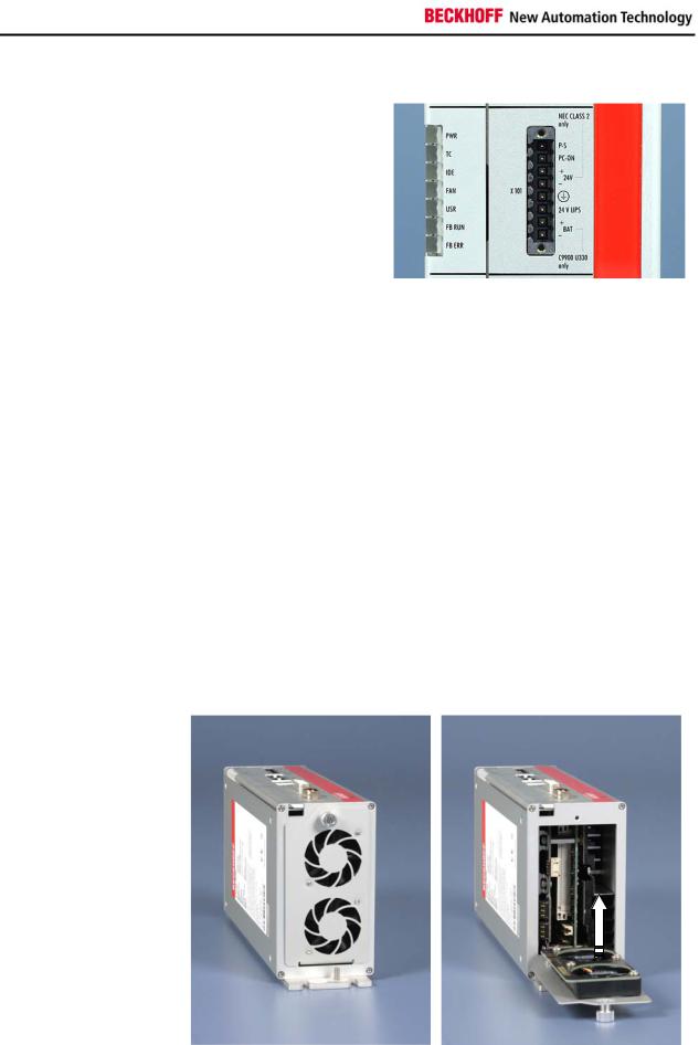
Status-LEDs
Description of the Status-
LEDs
2 |
X101 |
The Status-LEDs (2) are located near the power supply connector (X101):
1 |
PWR (Power): |
green |
Busy |
|
|
green blinking |
Standby |
2 |
TC (TwinCAT): |
red |
Stop Mode |
|
|
green |
Run Mode |
|
|
blue |
Configuration Mode |
3 |
IDE/ HDD: |
red |
Access to a memory |
|
|
|
device |
4 |
FAN: |
green |
Fans running |
|
|
red |
Fan Error |
5 |
USR (User): |
|
Programmable |
6 |
FB RUN (Fieldbus activ): |
green |
Activ |
|
|
red |
Not activ |
7 |
FB Error (Fieldbus Error): |
red |
Error |
|
|
|
|
Fan cartridge C6920
For optimal cooling the C6920 Industrial PC is equipped with a fan cartridge with two fans. The fan cartridge can be exchanged.
Replace the fans only with the identical type or an alternative type approved by Beckhoff.
View from the top
 2
2
1 
Exchanging the fan
cartridge For exchanging the fan cartridge (1), first solve the knurled screw (2). The cartridge can then be folded down and taken out.
8 |
C6920/ 25 |
Loading...