


BK2000

Beckhoff Lightbus Coupler
BK2000
valid for all BK2xxx bus coupler
Technical Documentation
2006-11-27
Version 1.4

Contents
2 BK2000
Contents
1. Foreword 3
Notes on the documentation 3
Liability Conditions 3
Delivery conditions 3
Copyright 3
Safety Instructions 4
State at Delivery 4
Description of safety symbols 4
2. Basic information 5
The Beckhoff bus terminal system 5
The interfaces 7
Power supply 7
Power supply to the power contacts 7
Power contacts 7
Field bus connection 8
Configuration interface 8
K-bus contacts 8
Supply isolation 8
The operating modes of the bus coupler 9
Mechanical construction 10
The peripheral data in the process image 12
Starting operation and diagnostics 15
3. Beckhoff-Lightbus coupler BK2000 17
Presentation of the Beckhoff-Lightbus system 17
4. Annex 24
Example: combination of a process image in the bus coupler 24
Examples S2100 Setup Digital Terminals 26
Representation of the analog signals in the process image 26
5. Support and Service 30
Beckhoff's branch offices and representatives 30
Beckhoff Headquarters 30

Foreword
BK2000 3
Foreword
Notes on the documentation
This description is only intended for the use of trained specialists in control and automation engineering
who are familiar with the applicable national standards. It is essential that the following notes and
explanations are followed when installing and commissioning these components.
Liability Conditions
The responsible staff must ensure that the application or use of the products described satisfy all the
requirements for safety, including all the relevant laws, regulations, guidelines and standards.
The documentation has been prepared with care. The products described are, however, constantly under
development. For that reason the documentation is not in every case checked for consistency with
performance data, standards or other characteristics. None of the statements of this manual represents a
guarantee (Garantie) in the meaning of § 443 BGB of the German Civil Code or a statement about the
contractually expected fitness for a particular purpose in the meaning of § 434 par. 1 sentence 1 BGB. In
the event that it contains technical or editorial errors, we retain the right to make alterations at any time
and without warning. No claims for the modification of products that have already been supplied may be
made on the basis of the data, diagrams and descriptions in this documentation.
Delivery conditions
In addition, the general delivery conditions of the company Beckhoff Automation GmbH apply.
Copyright
©
This documentation is copyrighted. Any reproduction or third party use of this publication, whether in
whole or in part, without the written permission of Beckhoff Automation GmbH, is forbidden.
Foreword
4 BK2000
Safety Instructions
State at Delivery
All the components are supplied in particular hardware and software configurations appropriate for the
application. Modifications to hardware or software configurations other than those described in the
documentation are not permitted, and nullify the liability of Beckhoff Automation GmbH.
Description of safety symbols
The following safety symbols are used in this documentation. They are intended to alert the reader to the
associated safety instructions..
Danger
This symbol is intended to highlight risks for the life or health of personnel.
Attention
This symbol is intended to highlight risks for equipment, materials or the
environment.
i
Note
This symbol indicates information that contributes to better understanding.

Basic information
BK2000 5
Basic information
The Beckhoff bus terminal system
Up to 64 bus terminals
each with 2 I/O channels
for any form of signal
Decentralized wiring of
the I/O level
IPC as control unit
Bus couplers for all current
bus systems
Standard C rail assembly
Modularity
Display of channel status
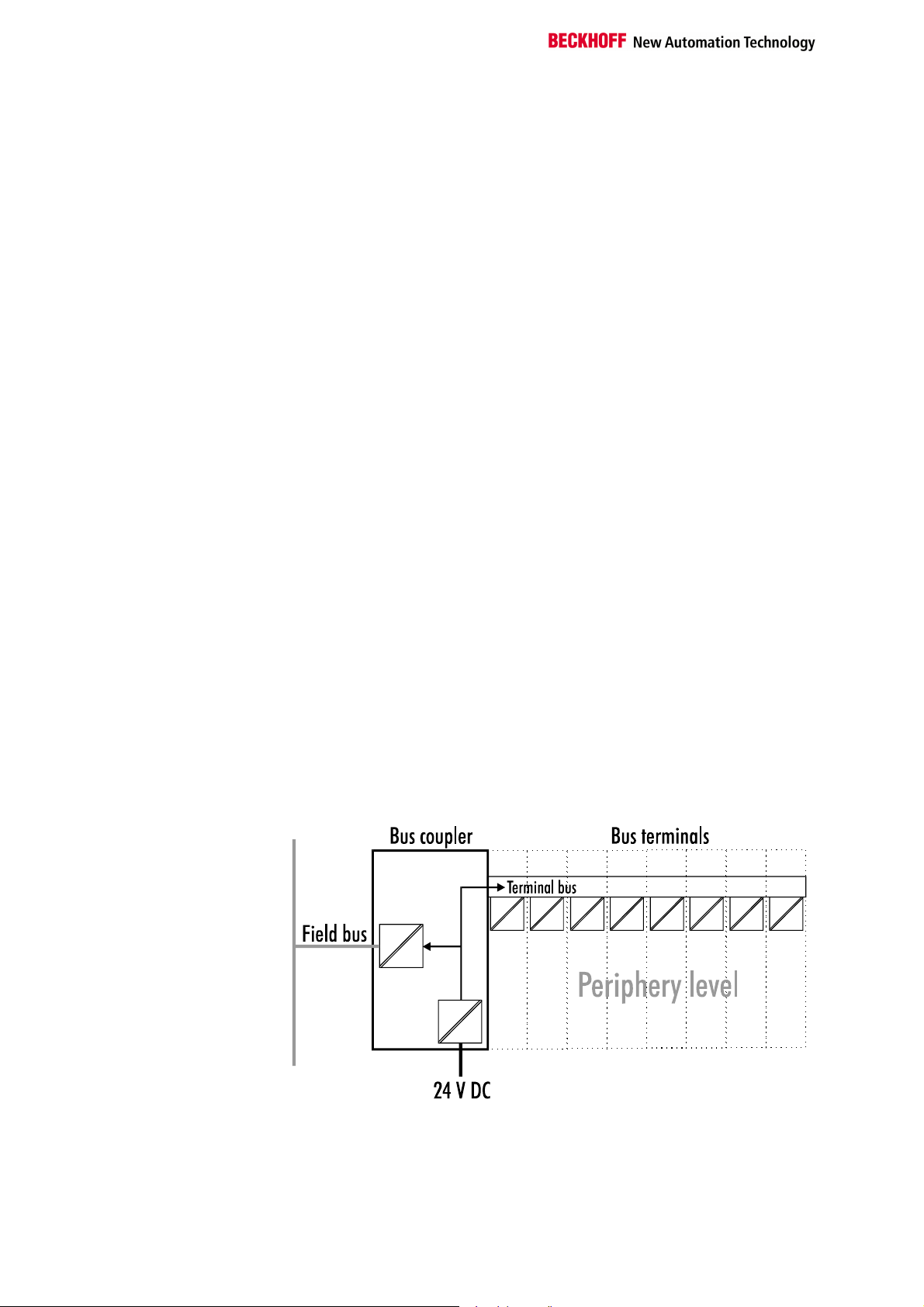
The bus terminal system is the universal connecting link between a
fieldbus system and the sensor/actor level. A unit consists of a bus coupler,
which is the interface to the fieldbus, and up to 64 electronic terminals, of
which the last is an end terminal. Terminals, each with two I/O channels,
are available for any form of technical signal and can be combined as
desired. The various types of terminal are all constructed in the same way,
so that the planning costs are kept extremely low. The height and depth of
the construction are calculated for compact terminal cabinets.
Fieldbus technology makes it possible to use compact control
architectures. The I/O level does not need to be taken right up to the
control unit. Sensors and actors can be connected decentrally with minimal
lengths of cable. You can position the control unit at any convenient
location in the installation. Using an industrial PC as control unit makes it
possible to implement the operating and monitoring element as part of the
control hardware, so the control unit can be located on an operating desk,
control point or similar. The bus terminals constitute the decentralized
input/output level of the control unit in the switch cabinet and its
subordinate terminal cabinets. As well as the sensor/actor level, the power
unit of the equipment is also controlled via the bus system. The bus
terminal replaces a conventional terminal as the cabling level in the switch
cabinet; the switch cabinet can be made smaller.
The Beckhoff bus terminal system combines the advantages of a bus
system with the functionality of compact terminals. Bus terminals can be
used on all current bus systems and serve to reduce the diversity of parts
in the control unit, while behaving like the conventional standard units for
the relevant bus system and supporting the entire range of functionality of
the bus system.
The simple and compact assembly on a standard C rail, and the direct
cabling of actors and sensors without cross connections between the
terminals, serve to standardize the installation, as does the uniformly
designed labeling.
The small size and great flexibility of the bus terminal system mean that
you can use it anywhere that you could use a terminal and use any type of
connection – analog, digital, serial or direct sensors.
The modular construction of the terminal row, using bus terminals with
various functions, limits the number of unused channels to at most one per
function. Two channels to a terminal is the optimum solution for the number
of unused channels and the cost per channel. The possibility of using
power input terminals to provide separate power supplies also helps to
minimize the number of unused channels.
The integrated light-emitting diodes close to the sensor/actor indicate the
status of each channel.
The K-bus
End terminal
Power input terminals
The K-bus is the path taken by data within the terminal row. The bus
coupler carries the K-bus through all the terminals by means of six contacts
on the side walls of the terminals, and the end terminal terminates the K-
bus. The user does not need to know anything about the function of the K-
bus or the internal operation of terminals and bus couplers. There are
numerous software tools available which provide for convenient planning,
configuration and operation.
Three power contacts pass the operating power to the following terminals.
Basic information
6 BK2000
for separately powered
groups
You can use power input terminals to subdivide the terminal row as desired
into groups, each with a separate power supply. These power input
terminals are not taken into account for addressing the terminals, you can
insert them at any position along the terminal row.
You can install up to 64 terminals on a terminal row, including power input
terminals and the end terminal.
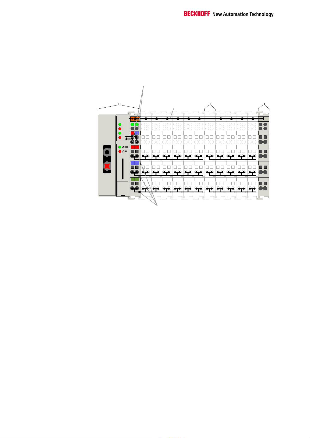
The principle of the bus
terminal
0201
+ +
PE
PE
BECKHOFF
24V
0V
K-Bus
End terminal
Electrical
Potential
supply
terminal
Power
Supply voltage
for the
bus coupler
CYC
ER R
W D
II/O -Li ght bus
Beckhoff-Lightbus
bus coupler
BK2000
BK 2000
Bus couplers for various
fieldbus systems
You can use a variety of bus couplers to attach the electronic terminal row
quickly and easily to the various fieldbus systems, and you can also sub-
sequently convert to a different fieldbus system. The bus coupler deals with
all the necessary monitoring and control tasks for operating the attached
bus terminals, indeed all the operation and configuration of the bus
terminals is carried out via the bus coupler. The fieldbus, K-bus and I/O
level are electrically isolated.
If the exchange of data across the fieldbus is temporarily interrupted, logic
states are preserved, digital outputs are cleared and analog outputs revert
to a reset value which can be individually configured for each output when
the equipment is set up. The default for the analog outputs is 0V or 0mA.
Digital outputs assume an inactive state. The bus couplers' timeouts
correspond to the usual times for the field bus system. When changing
over to a different bus system, pay attention to the change in timeouts in
the event of larger-scale bus system cycle times.
Basic information
BK2000 7
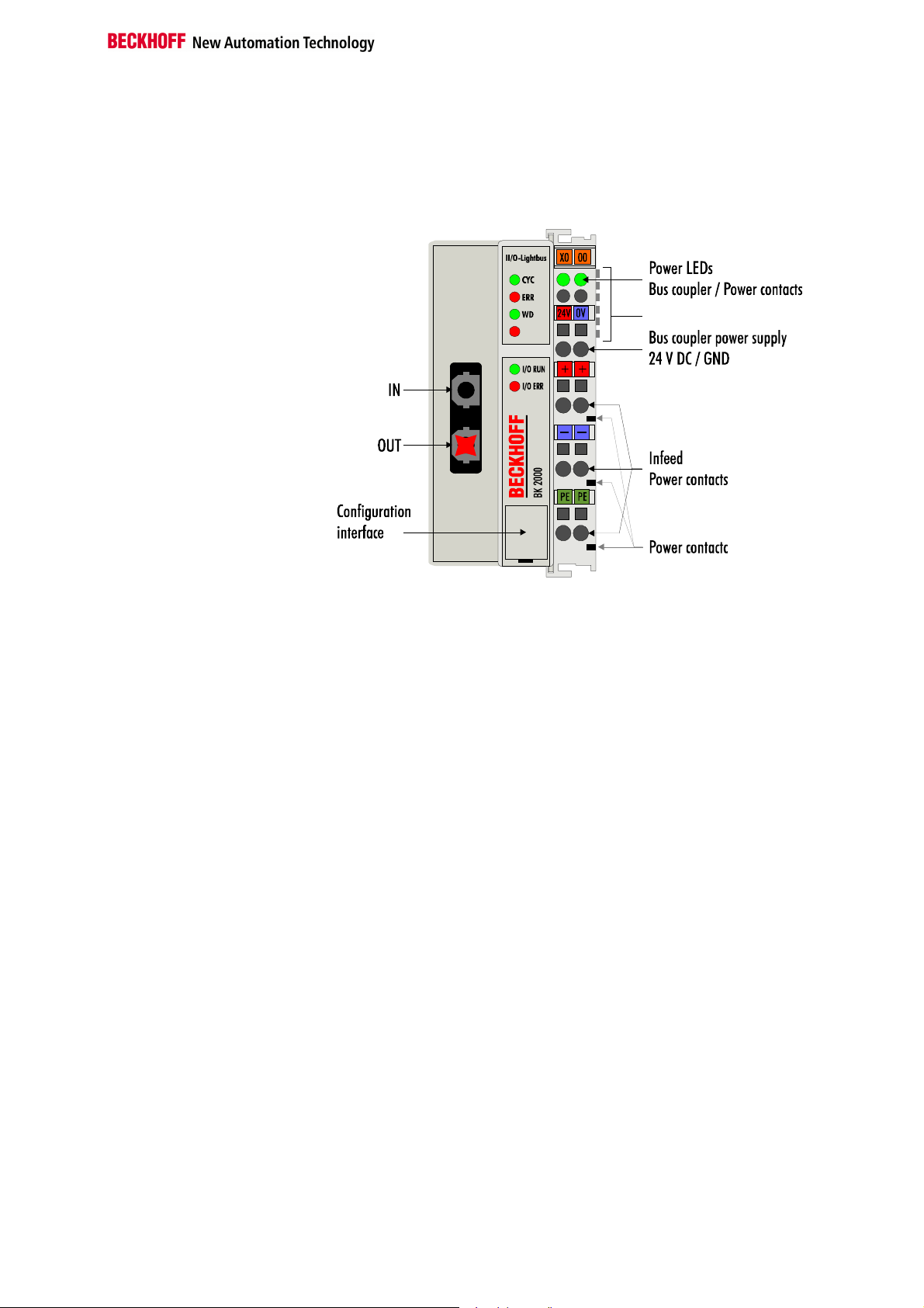
The interfaces
There are six ways of making a connection to a bus coupler. These
interfaces are designed as plug connections and spring terminals.
The Beckhoff-Lightbus –
coupler BK2000
K-Bus
Beckhoff-Lightbus
Power supply
24 V DC on the topmost
terminals “24 V” and “0 V”
The bus couplers need an operating power of 24 V DC which is connected
via the topmost spring terminals, labeled “24 V” and “0 V”. This power
supply serves not only the electronic components of the bus coupler but
(via the K-bus) also the bus terminals. The power supply of the bus coupler
circuitry and that of the K-bus are electrically isolated from the voltage of
the field level.
Power supply to the power contacts
Lower 3 terminal pairs for
power input
maximum 24 V
maximum 10 A
The six lower connections with spring terminals can be used to supply
power to the peripherals. The spring terminals are connected in pairs to the
power contacts. The power supply to the power contacts has no
connection to the power supply of the bus couplers. The power input is
designed to permit voltages up to 24 V. The pair-wise arrangement and the
electrical connection between the feed terminal contacts makes it possible
to loop through the wires connecting to different terminal points. The load
on the power contact may not continuously exceed 10 A. The current
capacity between two spring terminals is the same as the capacity of the
connecting wires.
Power contacts
Spring contacts at the side
On the right-hand side face of the bus coupler are three spring contacts
which are the power connections. The spring contacts are recessed in slots
to prevent them from being touched. When a bus terminal is connected,
the blade contacts on the left-hand side of the bus terminal are connected
to the spring contacts. The slot and key guides at the top and bottom of the
bus couplers and bus terminals ensure reliable location of the power
contacts.
Basic information
8 BK2000
Field bus connection
Beckhoff-Lightbus fiber-
optic conductor ring
Beckhoff Z1000 connector
There is a recessed front surface on the left-hand side. The typical
Beckhoff-Lightbus connectors can be inserted here. The Beckhoff-Lightbus
consists of a fiber-optic conductor ring into which the bus coupler is
inserted. In doing so, the connector out of which red light emerges when
the Beckhoff-Lightbus is switched on must be inserted in the top socket. In
the illustration, this is marked "IN". You need a fiber-optic conductor
connector type Beckhoff Z1000 for connection.
Configuration interface
Serial interface under the
front flap
On the lower part of the front face you will find the standbus couplers which
are fitted with an RS232 interface. The miniature plug can be attached to a
PC by means of a connection cable and the configuration software
KS2000. This interface enables you to configure the analog channels. You
can also access the functionality of the configuration interface via the
fieldbus by means of the ADS communications.
K-bus contacts
6 contacts at the side
The connections between the bus coupler and the bus terminals are
effected by gold contacts at the right-hand side of the bus coupler. When
the bus terminals are plugged together, these gold contacts automatically
complete the connection to the bus terminals. The K-bus is responsible for
the power supply to the electronic components of the K-bus in the bus
terminals, and for the exchange of data between the bus coupler and the
bus terminals. Part of the data exchange takes place via a ring structure
within the K-bus. Disengaging the K-bus, for example by pulling on one the
bus terminals, will break this circuit so that data can no longer be
exchanged. However, there are mechanisms in place which enable the bus
coupler to locate the interruption and report it.
Supply isolation
3 supply groups:
fieldbus
K-bus
peripheral level
The bus couplers operate with three independent supplies. The input
power supplies the electrically isolated K-bus circuitry in the bus coupler
and the K-bus itself. The power supply is also used to generate the
operating power for the fieldbus.
Note: All the bus terminals are electrically isolated from the K-bus, so that
the K-bus is completely electrically isolated.
Setting up the power levels
in the bus terminal system
Basic information
BK2000 9
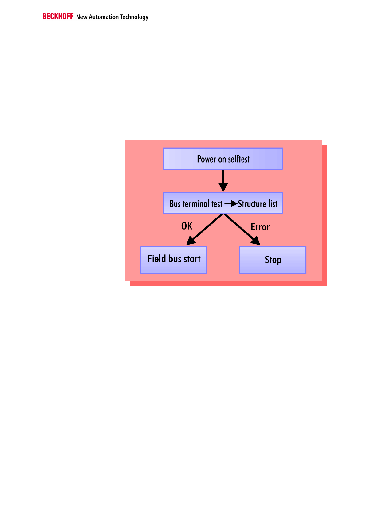
The operating modes of the bus coupler
When it is first switched on the bus coupler carries out a self-test to check
the functions of its components and the communications of the K-bus, and
while this is going on the red I/O LED will flash. When the self-test has
been completed successfully, the bus coupler will begin to test the
attached bus terminals (the “bus terminal test”) and read in the
configuration from which it constructs an internal structure list, which is not
accessible from outside. If an error occurs the bus coupler will enter the
operating mode “STOP”. If the start-up sequence is completed without
errors the bus coupler will enter the mode “fieldbus start”.
Start-up behavior of the bus
coupler
The bus coupler can only be returned to normal operation after fault
clearance by restarting the system.
 Loading...