


CX5120
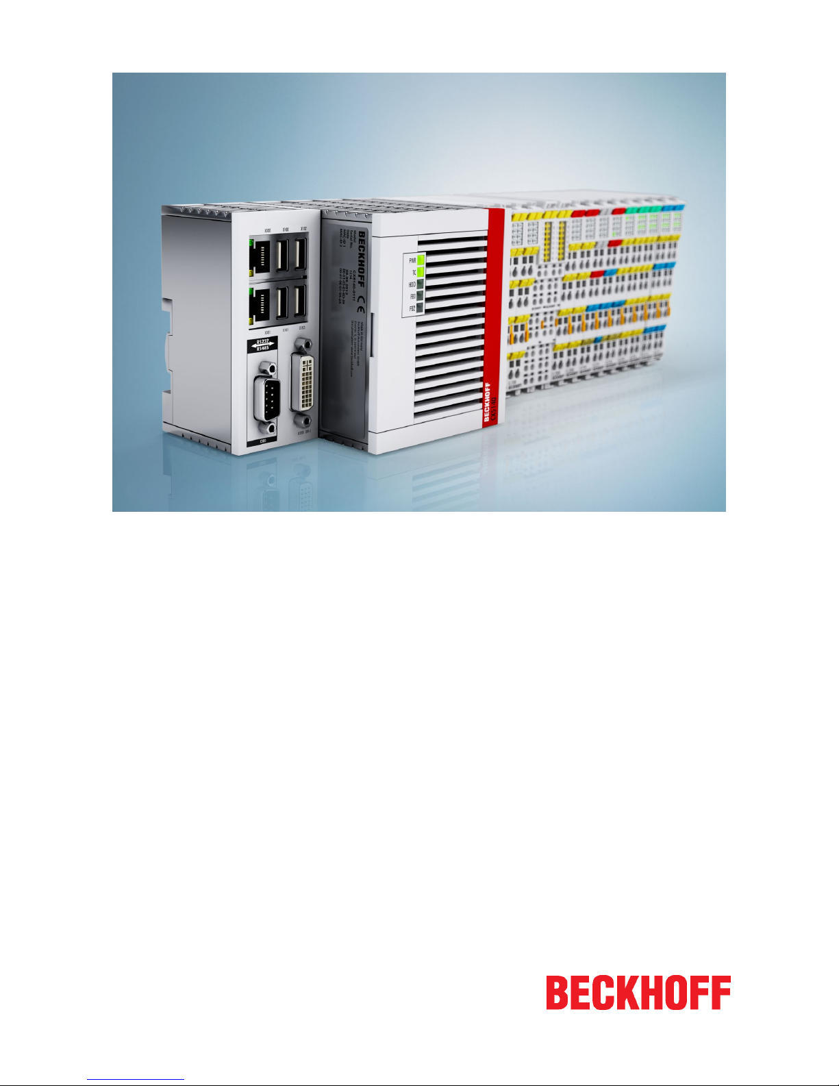
Manual
CX51x0
Embedded-PC
1.9
2018-01-25
Version:
Date:


Table of contents
CX51x0 3Version: 1.9
Table of contents
1 Notes on the documentation ....................................................................................................................5
1.1 Explanation of symbols................................................................................................................... 6
1.2 Related documents......................................................................................................................... 7
1.3 Documentation issue status............................................................................................................ 7
2 For your safety...........................................................................................................................................8
2.1 Intended use ................................................................................................................................... 8
2.2 Staff qualification ............................................................................................................................ 9
2.3 Safety instructions .......................................................................................................................... 9
3 Transport and storage ............................................................................................................................11
4 Product overview.....................................................................................................................................12
4.1 Configuration of the CX51x0 Embedded PC ................................................................................ 13
4.2 Name plate ................................................................................................................................... 14
4.3 Types ............................................................................................................................................ 15
4.4 Architecture overview ................................................................................................................... 16
5 Description of the interfaces ..................................................................................................................18
5.1 USB (X100, X101, X102, X103) ................................................................................................... 18
5.2 Ethernet RJ45 (X000, X001)......................................................................................................... 19
5.3 DVI-I (X200).................................................................................................................................. 20
5.4 Optional interfaces........................................................................................................................ 21
5.4.1 DVI-D (N010) ...................................................................................................................21
5.4.2 DisplayPort (N011)...........................................................................................................22
5.4.3 Audio interface (N020) .....................................................................................................23
5.4.4 RS232 (N030) ..................................................................................................................24
5.4.5 RS422/RS485 (N031) ......................................................................................................25
5.4.6 EtherCAT slave (B110) ....................................................................................................27
5.4.7 PROFIBUS (x310)............................................................................................................28
5.4.8 CANopen (x510) ..............................................................................................................29
5.4.9 PROFINET RT (x930)......................................................................................................30
6 Commissioning........................................................................................................................................31
6.1 Assembly ...................................................................................................................................... 31
6.1.1 Note the permissible installation positions ......................................................................31
6.1.2 Attaching on mounting rail ...............................................................................................33
6.1.3 MicroSD card installation and removal ............................................................................34
6.1.4 CFast card installation and removal.................................................................................35
6.1.5 Installing passive EtherCAT Terminals ............................................................................36
6.2 Connecting the power supply ....................................................................................................... 37
6.3 Switching on ................................................................................................................................. 39
6.4 Switching off ................................................................................................................................. 39
7 Configuration ...........................................................................................................................................40
7.1 Windows Embedded Compact 7 .................................................................................................. 40
7.1.1 Setting up the audio interface (N020) ..............................................................................40
7.2 Windows Embedded Standard 7 P............................................................................................... 41
7.2.1 Identification of the Ethernet interfaces (X000, X001) .....................................................41
7.2.2 Enabling jumbo frames ....................................................................................................42
7.2.3 Set NIC Teaming..............................................................................................................43
7.2.4 Restoring the Beckhoff real-time driver............................................................................45

Table of contents
CX51x04 Version: 1.9
7.3 Windows 10 IoT Enterprise LTSB................................................................................................. 46
7.3.1 Identification of the Ethernet interfaces (X000, X001) .....................................................46
7.3.2 Enabling jumbo frames ....................................................................................................47
7.3.3 Set NIC Teaming..............................................................................................................48
7.3.4 Restoring the Beckhoff real-time driver............................................................................50
7.4 Beckhoff Device Manager............................................................................................................. 51
7.4.1 Starting the Beckhoff Device Manager ............................................................................51
7.4.2 Enabling a remote display................................................................................................52
7.5 TwinCAT ....................................................................................................................................... 53
7.5.1 Tree view..........................................................................................................................53
7.5.2 Searching for target systems ...........................................................................................54
7.5.3 Adding an Embedded PC ................................................................................................56
7.5.4 Configure the serial interface (N03x) ...............................................................................57
7.5.5 Configuring EtherCAT cable redundancy. .......................................................................59
7.5.6 Using a hardware watchdog ............................................................................................61
8 1-second UPS (persistent data) .............................................................................................................63
8.1 BIOS settings................................................................................................................................ 64
8.2 Windows write filter....................................................................................................................... 66
8.3 FB_S_UPS_CX51x0..................................................................................................................... 67
8.4 Mode and status of the function block .......................................................................................... 69
8.5 Checking the validity of the variables ........................................................................................... 70
8.5.1 SYSTEMINFOTYPE ........................................................................................................70
8.5.2 PlcAppSystemInfo............................................................................................................72
9 Error handling and diagnostics .............................................................................................................73
9.1 Diagnostic LEDs ........................................................................................................................... 73
9.2 Power supply terminal LEDs in K-bus mode ................................................................................ 74
9.3 Power supply terminal LEDs in K-bus mode ................................................................................ 77
9.4 Faults ............................................................................................................................................ 78
10 Care and maintenance ...........................................................................................................................79
10.1 Replace the battery....................................................................................................................... 79
11 Decommissioning....................................................................................................................................80
11.1 Removing cables .......................................................................................................................... 80
11.2 Dismantling the Embedded PC..................................................................................................... 81
12 Technical data..........................................................................................................................................82
13 Appendix ..................................................................................................................................................84
13.1 Accessories .................................................................................................................................. 84
13.2 Certifications ................................................................................................................................. 85
13.3 Support and Service ..................................................................................................................... 86
List of tables ............................................................................................................................................87
List of figures...........................................................................................................................................88

Notes on the documentation
CX51x0 5Version: 1.9
1 Notes on the documentation
This description is only intended for the use of trained specialists in control and automation engineering who
are familiar with the applicable national standards.
It is essential that the documentation and the following notes and explanations are followed when installing
and commissioning the components.
It is the duty of the technical personnel to use the documentation published at the respective time of each
installation and commissioning.
The responsible staff must ensure that the application or use of the products described satisfy all the
requirements for safety, including all the relevant laws, regulations, guidelines and standards.
Disclaimer
The documentation has been prepared with care. The products described are, however, constantly under
development.
We reserve the right to revise and change the documentation at any time and without prior announcement.
No claims for the modification of products that have already been supplied may be made on the basis of the
data, diagrams and descriptions in this documentation.
Trademarks
Beckhoff®, TwinCAT®, EtherCAT®, Safety over EtherCAT®, TwinSAFE®, XFC® and XTS® are registered
trademarks of and licensed by Beckhoff Automation GmbH.
Other designations used in this publication may be trademarks whose use by third parties for their own
purposes could violate the rights of the owners.
Patent Pending
The EtherCAT Technology is covered, including but not limited to the following patent applications and
patents:
EP1590927, EP1789857, DE102004044764, DE102007017835
with corresponding applications or registrations in various other countries.
The TwinCAT Technology is covered, including but not limited to the following patent applications and
patents:
EP0851348, US6167425 with corresponding applications or registrations in various other countries.
EtherCAT® is registered trademark and patented technology, licensed by Beckhoff Automation GmbH,
Germany
Copyright
© Beckhoff Automation GmbH & Co. KG, Germany.
The reproduction, distribution and utilization of this document as well as the communication of its contents to
others without express authorization are prohibited.
Offenders will be held liable for the payment of damages. All rights reserved in the event of the grant of a
patent, utility model or design.
Notes on the documentation
CX51x06 Version: 1.9
1.1 Explanation of symbols
The following symbols with corresponding warnings or explanatory text are used in the documentation. Read
and follow the warnings.
Symbols that warn of personal injury:
DANGER
Serious risk of injury
Note this warning. Hazard with high risk of death or serious injury.
WARNING
Risk of injury
Note this warning. Hazard with medium risk of death or serious injury.
CAUTION
Personal injuries
Note this warning. Hazard with a low degree of risk, which could lead to minor or moderate
injury.
Symbols that warn of damage to property or equipment:
Attention
Damage to the devices or environment
Note this warning. Risk of damage to the environment and equipment.
Symbols indicating further information or tips:
Note
Tip or pointer
This symbol indicates information that contributes to better understanding.
Notes on the documentation
CX51x0 7Version: 1.9
1.2 Related documents
Information on operation in potentially explosive atmospheres
Please refer to the corresponding documentation for important information and notes regarding operation of
the CX51x0 Embedded PCs in potentially explosive atmospheres. In particular, read and follow the sections
on safety contained in this document:
http://www.beckhoff.de
Document name
Notes on using the CX51x0 in potentially explosive atmospheres.
Retaining the documentation
This documentation is part of the Embedded PC. Keep the documentation in the immediate vicinity of the
device throughout its entire service life. Ensure that personnel have access to the documentation at all times.
Pass on the documentation to subsequent users, and in addition ensure that all supplementary information is
included in the documentation.
1.3 Documentation issue status
Version Modifications
0.1 Preliminary version
1.0 First publication
1.1 UL requirements added
1.2 Values changed in chapter Seconds UPS
1.3 Architecture overview added
1.4 Revised description of the Diagnostic LEDs
1.5 Note about driver support for serial port added
1.6 Chapter Types reworked
1.7 Chapter 1-seconds UPS reworked
1.8 Documentation restructured and revised
1.9 Information for operation in potentially explosive
atmospheres added

For your safety
CX51x08 Version: 1.9
2 For your safety
Read the chapter on safety and follow the instructions in order to protect from personal injury and damage to
equipment.
Limitation of liability
All the components are supplied in particular hardware and software configurations appropriate for the
application. Unauthorized modifications and changes to the hardware or software configuration, which go
beyond the documented options, are prohibited and nullify the liability of Beckhoff Automation GmbH & Co.
KG.
In addition, the following actions are excluded from the liability of Beckhoff Automation GmbH & Co. KG:
• Failure to comply with this documentation.
• Improper use.
• Use of untrained personnel.
• Use of unauthorized replacement parts.
2.1 Intended use
The CX51x0 Embedded PC is a control system and is intended for mounting on a DIN rail in a control
cabinet or terminal box. The Embedded PC series is used in conjunction with Bus Terminals for recording
digital or analog signals from sensors and transferring them to actuators or higher-level controllers.
The Embedded PC is designed for a working environment that meets the requirements of protection class
IP20. This involves finger protection and protection against solid foreign objects up to 12.5 mm, but not
protection against water. Operation of the devices in wet and dusty environments is not permitted, unless
specified otherwise. The specified limits for electrical and technical data must be adhered to.
Potentially explosive atmospheres
Device modification CX2900-0107 is mandatory for operation of the Embedded PC in potentially explosive
atmospheres, zone 2/22. The device modification includes a factory-installed retainer bracket for
mechanically securing the plug connectors.
The device modification is mandatory for operating the Embedded PC in the following potentially explosive
atmospheres:
1. For Zone 2 atmospheres in which gas is present as a combustible material. Zone 2 means that an explosive atmosphere does usually not occur during normal operation, or only for a short time.
2. For Zone 22 atmospheres in which dust is present as a combustible material. Zone 22 means that an
explosive atmosphere in the form of a cloud does usually not occur during normal operation, or only
for a short time.
The Embedded PC must be installed in a housing, which ensures protection class IP 54 for gas according to
EN 60079-15. A housing with protection class IP 54 is required for non-conductive dust. IP 6X is required for
conductive dust according to EN 60079-31.
Improper use
The Embedded PC is not suitable for operation in the following areas:
• In potentially explosive atmospheres, the Embedded PC may not be used in other zones except for
2/22 and not without a suitable housing.
• Areas with an aggressive environment, e.g. aggressive gases or chemicals.
• Living areas. In living areas, the relevant standards and guidelines for interference emissions must be
adhered to, and the devices must be installed in housings or control boxes with suitable attenuation of
shielding.
For your safety
CX51x0 9Version: 1.9
2.2 Staff qualification
All operations involving Beckhoff software and hardware may only be carried out by qualified personnel with
knowledge of control and automation engineering. The qualified personnel must have knowledge of the
administration of the Embedded PC and the associated network.
All interventions must be carried out with knowledge of control programming, and the qualified personnel
must be familiar with the current standards and guidelines for the automation environment.
2.3 Safety instructions
The following safety instructions must be followed during installation and working with networks and the
software.
Explosion protection
Device modification CX2900-0107 is mandatory for operation of the Embedded PC in potentially explosive
atmospheres, zone 2/22. The device modification entails the modification and relocation of the device label
and a factory-fitted retainer bracket for mechanically securing the connectors.
WARNING
Operation without device modification
Without the CX2900-0107 device modification, the USB plug connectors may slip out of the
USB ports due to vibration, which may trigger a deflagration or explosion.
The Embedded PC must only be used with the device modification, and the USB plug connectors must be secured to the retainer brackets with cable ties.
Tighten the screws of the DVI plug connector and, if present, also the screws of the fieldbus plug connectors,
in order to prevent the plug connectors slipping out. Only use RJ45 connectors with an intact latch. Use
cable ties to secure the USB plug connectors and RJ45 connectors to the retainer brackets.
The CXxxxx-N020 optional interface (audio interface) may not be used in potentially explosive atmospheres.
The Embedded PC must be installed in a housing, which ensures protection class IP54 for gas according to
EN 60079-15. A housing with protection class IP54 is required for non-conductive dust. IP6X is required for
conductive dust according to EN 60079-31.
Observe the temperature at the cable entry points into the housing. If the temperature during nominal
operation is higher than 70 °C at the entry points or higher than 80 °C at the wire branching points, cables
must be selected that are designed for these high temperatures and operation in potentially explosive
atmospheres.
Maintain the prescribed ambient temperature during operation. The permissible ambient temperature lies
within the range from 0 °C ... +60 °C.
Take measures to prevent the rated operating voltage exceeding 119 V through short-term interference
voltages.
Switch off the power supply and ensure that no explosive atmosphere occurs when:
• Bus Terminals are connected or removed,
• the Embedded PC is wired or cables are connected,
• the front flap is opened,
• the CFast card, MicroSD card or battery is replaced.
Mounting
• Never work on live equipment. Always switch off the power supply for the device before installation,
troubleshooting or maintenance. Protect the device against unintentional switching on.
• Observe the relevant accident prevention regulations for your machine (e.g. the BGV A 3, electrical
systems and equipment).

For your safety
CX51x010 Version: 1.9
• Ensure standard-compliant connection and avoid risks to personnel. Ensure that data and supply
cables are laid in a standard-compliant manner and ensure correct pin assignment.
• Observe the relevant EMC guidelines for your application.
• Avoid polarity reversal of the data and supply cables, as this may cause damage to the equipment.
• The devices contain electronic components, which may be destroyed by electrostatic discharge when
touched. Observe the safety precautions against electrostatic discharge according to DIN EN
61340-5-1/-3.
Working with networks
• Restrict access to all devices to an authorized circle of persons.
• Change the default passwords to reduce the risk of unauthorized access. Regularly change the
passwords.
• Install the devices behind a firewall.
• Apply the IT security precautions according to IEC 62443, in order to limit access to and control of
devices and networks.
Working with the software
• Use up-to-date security software. The safe function of the PC can be compromised by malicious
software such as viruses or Trojans.
• The sensitivity of a PC against malicious software increases with the number of installed and active
software.
• Uninstall or disable unnecessary software.
Further information about the safe handling of networks and software can be found in the Beckhoff
Information System:
http://infosys.beckhoff.de
Document name
Documentation about IPC Security
Transport and storage
CX51x0 11Version: 1.9
3 Transport and storage
Transport
Attention
Short circuit due to moisture
Moisture can form during transport in cold weather or in the event of large temperature fluctuations.
Avoid moisture formation (condensation) in the Embedded PC, and leave it to adjust to
room temperature slowly. If condensation has occurred, wait at least 12 hours before
switching on the Embedded PC.
Despite the robust design of the unit, the components are sensitive to strong vibrations and impacts. During
transport the Embedded PC must be protected from
• mechanical stress and
• use the original packaging.
Table1: Dimensions and weight of the individual modules.
CX5120 CX5130 CX5140
Dimensions (W x H x D) 123 mm x 100 mm x 91
mm
142 mm x 100 mm x 91 mm
Weight approx. 975 g approx. 1095 g approx. 1095 g
Storage
• The battery should be removed if the Embedded PC is stored at temperatures above 60°C. The
battery should be stored separate from the Embedded PC in a dry environment at a temperature
between 0 °C and 30 °C.
The preset date and time are lost if the battery is removed.
• Store the Embedded PC in the original packaging.

Product overview
CX51x012 Version: 1.9
4 Product overview
The CX5100 product family comprises three Embedded PCs, which differ in terms of processor type, RAM
and housing size. The CX51x0 Embedded PC is a full-fledged PC with the following basic configuration:
• CFast card slot,
• MicroSD card slot,
• two independent Gbit Ethernet interfaces,
• four USB 2.0 interfaces,
• and a DVI-I interface.
Suitable operating systems are Microsoft Windows 10 IoT Enterprise LTSB, Microsoft Windows Embedded
Standard 7 P or Microsoft Windows Embedded Compact 7.
The Embedded PC features an internal 1-second UPS as persistent data memory. In the event of a power
failure the 1-second UPS can store up to 1 MB of persistent data on the CFast card or MicroSD card.
The Embedded PC can be ordered ex factory with an optional interface. The optional interface cannot be
retrofitted.
Table2: Available optional interfaces for the CX51x0.
CX51x0-xxxx Optional interfaces
CX51x0-N010 DVI-D, additional DVI-D socket for clone and extended display mode.
1)
CX51x0-N011 DisplayPort, additional DisplayPort for clone and extended display mode.
1)
CX51x0-N020 Audio interface, 3 x 3.5 mm jack plug, Line-In, Mic-In, Line-Out
CX51x0-N030 RS232, D-sub connector, 9-pin.
CX51x0-N031 RS422/RS485, D-sub socket, 9-pin.
CX51x0-B110 EtherCAT slave, EtherCAT IN and OUT (2 x RJ45).
CX51x0-M310 PROFIBUS master, D-sub socket, 9-pin.
CX51x0-B310 PROFIBUS slave, D-sub socket, 9-pin.
CX51x0-M510 CANopen master, D-sub connector, 9-pin.
CX51x0-B510 CANopen slave, D-sub connector, 9-pin.
CX51x0-M930 PROFINET RT, controller, Ethernet (2 x RJ-45).
CX51x0-B930 PROFINET RT, device, Ethernet (2 x RJ-45 switch).
1)
Only available for CX5130 and CX5140.
Power supply terminal
The power supply terminal for the Embedded PC is located on the right-hand side. Bus Terminals (K-bus) or
EtherCAT Terminals (E-bus) can be attached on the right-hand side of the power supply unit. The power
supply terminal automatically recognizes the respective bus system (K-bus or E-bus).
Software
In combination with the TwinCAT automation software, the CX51x0 Embedded PC becomes a powerful IEC
61131-3 PLC with up to four user tasks.
Additionally, Motion Control tasks can also be executed. It may be possible to control several servo axes,
depending on the required sampling time. In addition to simple point-to-point movements, it is possible to
execute more complex multi-axis functions such as electronic gear unit, cam plate and flying saw.
In addition to real-time execution of control tasks, the TwinCAT real-time kernel ensures that enough time
remains for the user interface (HMI), to communicate with the real-time components via software interfaces
such as ADS or OPC.
Product overview
CX51x0 13Version: 1.9
4.1 Configuration of the CX51x0 Embedded PC
1
2
8
3
5
9
11
12
13
15
4
14
16
6
7
10
11
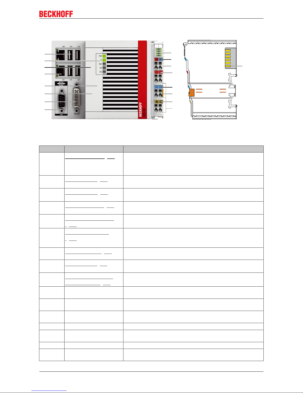
Fig.1: Example: CX5140 Embedded PC.
Table3: Legend for the configuration.
No. Component Description
1
Optional interface [}21]
(X300).
Space for interfaces such as RS232, EtherCAT, CANopen or
others.
The optional interface must be ordered ex factory and cannot be
retrofitted retrospectively.
2
DVI-I interface [}20]
(X200).
Interface for a monitor or Panel.
3
CFast card slot [}35]
(under the front flap).
Slot for industrial CFast cards.
4
MicroSD card slot [}34]
(under the front flap).
Slot for industrial MicroSD cards.
5
RJ45 Ethernet interfaces
[}19] (X000, X001).
For connecting to local networks or the internet.
6
Battery compartment
[}79] (under the front
flap).
Power supply for the battery-backed clock for time and date.
7
Diagnostic LEDs. [}73]
Diagnostic LEDs for power supply, TwinCAT and the optional
interface.
8
USB interfaces [}18]
(X100, X101, X102, X103).
Interfaces for peripherals such as mouse, keyboard or USB
memory.
9
Diagnostic LEDs, power
supply terminal. [}74]
Diagnosis of the power supply for the Embedded PC and the
Terminal Bus. Status of the E-bus and K-bus communication.
10 Spring-loaded terminals,
+24 V and 0 V
Power supply for Embedded PC.
11 Terminal bus (K- or E-bus) Interface for EtherCAT Terminals or Bus Terminals. Data exchange
and supply.
12 Spring-loaded terminal, +24VPower supply for Bus Terminals via power contact.
13 Spring-loaded terminal, 0 V Power supply for Bus Terminals via power contact.
14 Terminal release Releases the power supply terminal and therefore the Embedded
PC from the mounting rail.
15 Spring-loaded terminal, PE Spring-loaded terminal for power contact PE.
16 Power contacts, +24 V, 0
V, PE
Power contacts for Bus Terminals.
Product overview
CX51x014 Version: 1.9
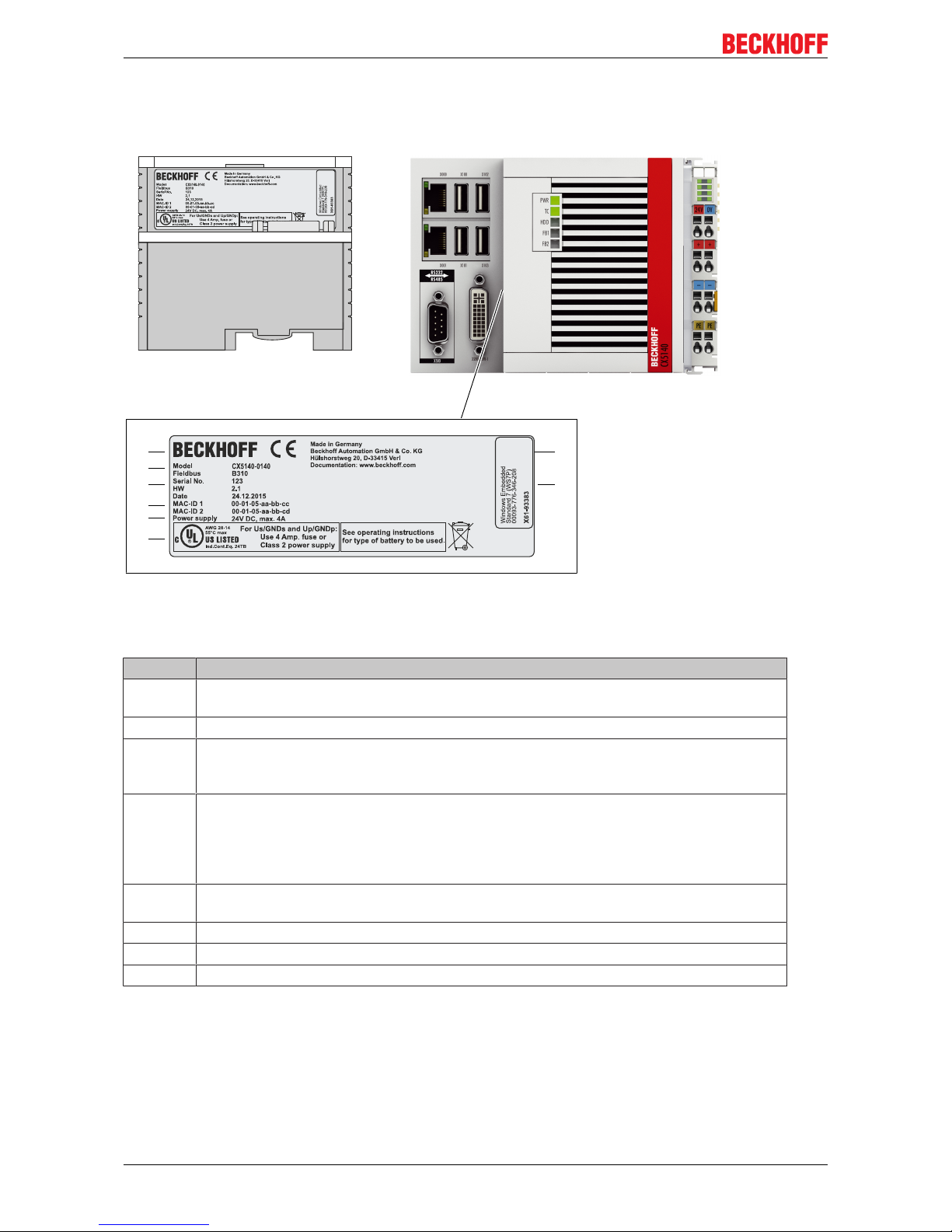
4.2 Name plate
The CX51x0 Embedded PC features a name plate on the left-hand side of the housing.
1
2
3
6
4
5
7
8
Fig.2: CX51x0 name plate.
Table4: Legend for the name plate.
No. Description
1 UL approval with prescribed information on power supply, fuse, temperature and cable
cross-sections.
2 Information on the power supply unit. 24 V DC, 4 A max.
3 MAC addresses of the integrated Ethernet ports.
By default, the host name is formed from "CX-" plus the last 3 bytes of the MAC address:
Example: the host name CX-aabbcc is formed from the MAC address 00-01-05-aa-bb-cc.
4 Information on:
• serial number,
• hardware version
• and date of manufacture.
5 Information on the model. The last four numerals relate to the configuration of Embedded
PC.
6 Manufacturer information including address.
7 CE compliant.
8 Windows license sticker (optional).
Product overview
CX51x0 15Version: 1.9
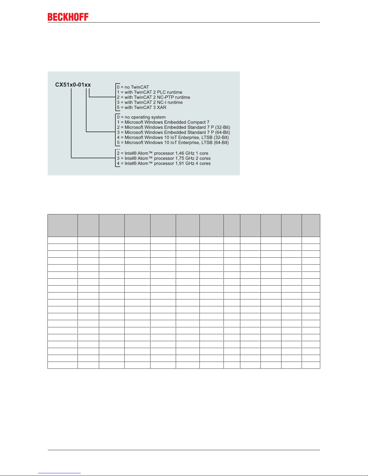
4.3 Types
The CX51x0 Embedded PC can be ordered with different software options. Use this overview in conjunction
with the information on the name plate to ascertain the operating system and the TwinCAT version of the
Embedded PC.
Fig.3: Nomenclature for the CX51x0 Embedded PC.
The Embedded PCs CX5120, CX5130 and CX5140 are available with the following software options:
Table5: CX51x0, ordering information for software.
Modul no
operatingsystem
Windows
Embedded
Compact 7
Windows
Embedded
Standard 7
P (32-Bit)
Windows
Embedded
Standard 7
P (64-Bit)
Windows
10 IoT Enterprise,
(32 Bit)
Windows
10 IoT Enterprise,
(64 Bit)
no
TwinCAT
TwinCAT 2
PLCRuntime
TwinCAT 2
NC-PTPRuntime
TwinCAT 2
NC-IRuntime
TwinCAT 3
XAR
CX51x0-0100 X - - - - - X - - - -
CX51x0-0110 - X
1)
- - - - X - - - -
CX51x0-0111 - X
1)
- - - - - X - - -
CX51x0-0112 - X
1)
- - - - - - X - -
CX51x0-0113 - X
1)
- - - - - - - X -
CX51x0-0115 - X
1)
- - - - - - - - X
CX51x0-0120 - - X - - - X - - - -
CX51x0-0121 - - X - - - - X - - -
CX51x0-0122 - - X - - - - - X - -
CX51x0-0123 - - X - - - - - - X -
CX51x0-0125 - - X - - - - - - - X
CX51x0-0130 - - - X - - X - - - -
CX51x0-0135 - - - X - - - - - - X
CX51x0-0140 - - - - X - X - - - -
CX51x0-0141 - - - - X - - X - - -
CX51x0-0142 - - - - X - - - X - -
CX51x0-0143 - - - - X - - - - X -
CX51x0-0150 - - - - - X X - - - -
CX51x0-0155 - - - - - X - - - - X
1)
With Microsoft Windows Embedded Compact 7 only one core is supported.
A CX51x0 Embedded PC with Microsoft Windows Embedded Standard 7 P (32-bit) requires a CFast card
with a minimum capacity of 8 GB. For Microsoft Windows Embedded Standard 7 P (64-bit) and Microsoft
Windows 10 IoT Enterprise (32- and 64-bit) a CFast card with a minimum capacity of 16 GB is required.
Product overview
CX51x016 Version: 1.9
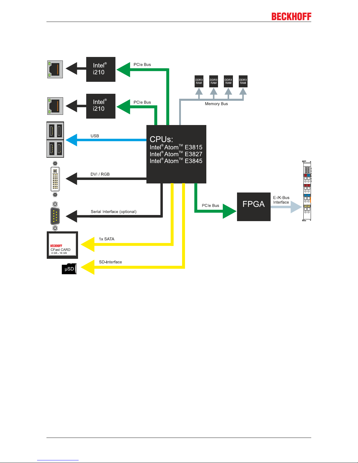
4.4 Architecture overview
The Embedded PCs of the CX51x0 family all have the same architecture. This is described below.
The CX51x0 Embedded PCs are based on the Intel Atom microarchitecture, which was developed by Intel.
The following CPUs are used:
• Intel®AtomTM E3815 (Singlecore)
• Intel®AtomTM E3827 (Dualcore)
• Intel®AtomTM E3845 (Quadcore)
In addition to the arithmetic unit, the CPU also contains the memory controller and the graphics controller.
The processors use the Intel® HD Graphics core. For details on the CPUs please refer to Intel. The memory
is connected directly to the CPU. The Embedded PCs are available in two memory configurations: 2GB or
4GB DDR3 RAM. The memory is not extendable and must be ordered ex factory.
The CPU provides all required interfaces:
• 1 PCI lane for each of the two Intel® i210 Gigabit Ethernet controllers
• 4x USB 2.0 (interfaces)
• DVI-I and DVI-D interface (2nd interface optional in CX51x0-N010)
• Serial interface (CX51x0-N03x)
• 1 PCIe for FPGA for K-/E-bus and NOV-RAM
• 1 SATA for CFast card interface
• 1 IDE for MicroSD card interface

Product overview
CX51x0 17Version: 1.9
The interfaces (USB, DVI, and LAN) are standard interfaces. Devices that meet the corresponding standard
can be connected to and operated at these interfaces. A VGA monitor can be connected to the DVI-I
interface with an adapter.
Intel® i210 Gigabit Ethernet controllers are used as network controllers. There are two independent Ethernet
interfaces. Both LAN interfaces are gigabit-capable.
Description of the interfaces
CX51x018 Version: 1.9
5 Description of the interfaces
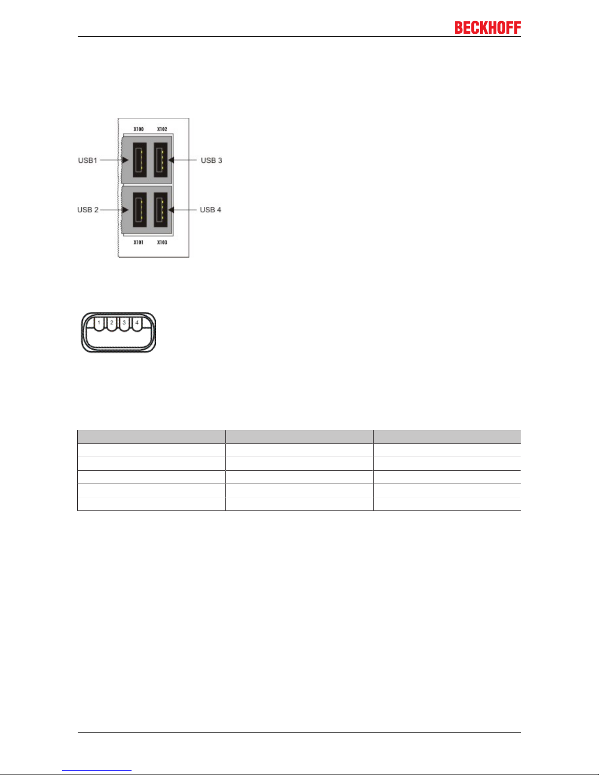
5.1 USB (X100, X101, X102, X103)
Fig.4: USB interfaces (X100, X101, X102, X103).
The Embedded PC has four independent USB interfaces for connecting keyboards, mice, touchscreens and
other input or data storage devices.
Fig.5: USB interface, pin numbering.
Note the power consumption of the individual devices. Each interface is limited to 500mA. The USB
interface is of type A and corresponds to the USB 2.0 specification.
Table6: USB interfaces (X100, X101, X102, X103), pin assignment.
Pin Assignment Typical assignment
1 VBUS Red
2 D- White
3 D+ Green
4 GND Black
Shell Shield Drain Wire
Description of the interfaces
CX51x0 19Version: 1.9
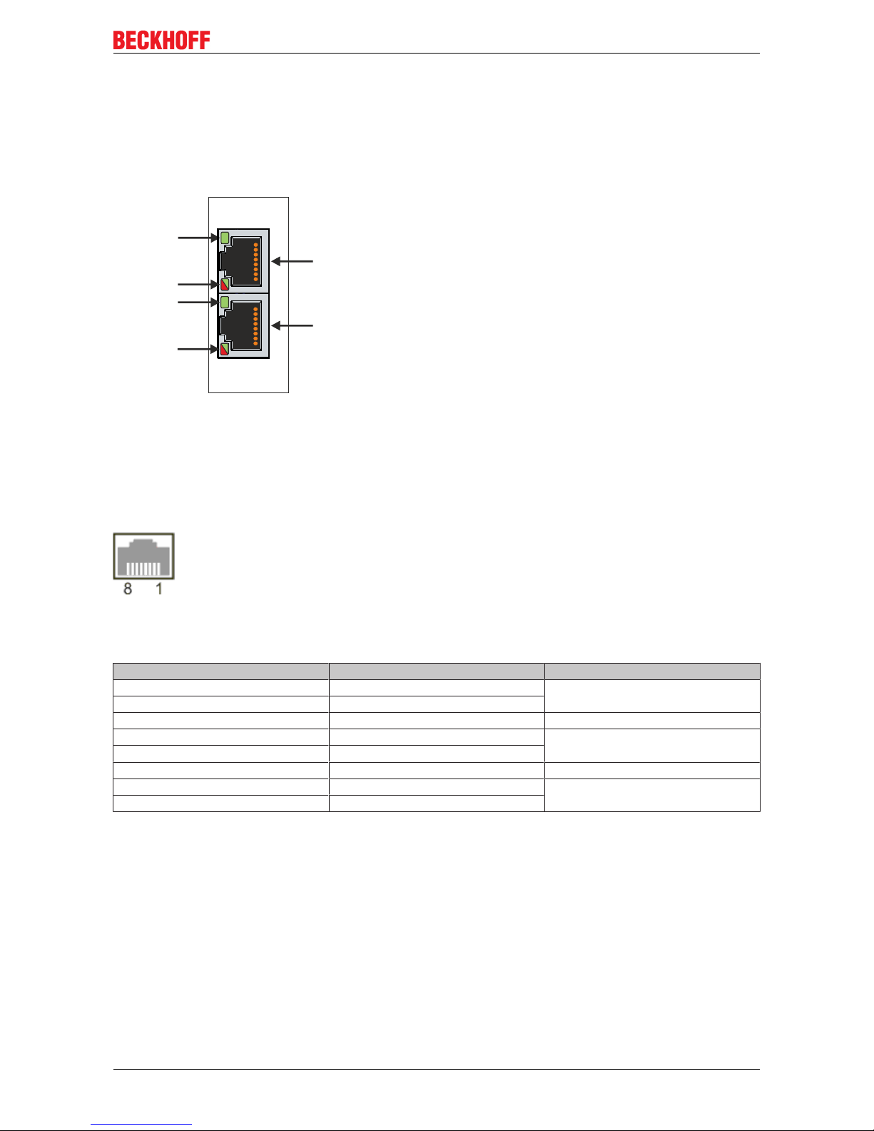
5.2 Ethernet RJ45 (X000, X001)
The two Ethernet interfaces are independent; no switch is integrated. The independent Ethernet interfaces
can be configured in different ways. In delivery state the Ethernet interfaces (X000, X001) are configured for
EtherCAT communication.
Note that an additional switch is required for a line topology.
X000
X001
LAN 1
LAN 2
LINK / ACT 2
SPEED 2
LINK / ACT 1
SPEED 1
Fig.6: Ethernet interface X000, X001.
Both Ethernet interfaces reach speeds of 10 / 100 / 1000 Mbit. The LEDs on the left of the interfaces indicate
the connection status. The upper LED (LINK/ACT) indicates whether the interface is connected to a network.
If this is the case the LED is green. The LED flashes when data transfer is in progress.
The lower LED (SPEED) indicates the connection speed. The LED does not light up if the speed is 10 Mbit.
The LED is green if the speed is 100 Mbit. The LED lights up red if the speed is 1000 Mbit (gigabit).
Fig.7: Ethernet interface, pin numbering.
Table7: Ethernet interface X000 and X001, pin assignment.
PIN Signal Description
1 T2 + Pair 2
2 T2 -
3 T3 + Pair 3
4 T1 + Pair 1
5 T1 -
6 T3 - Pair 3
7 T4 + Pair 4
8 T4 -
Description of the interfaces
CX51x020 Version: 1.9
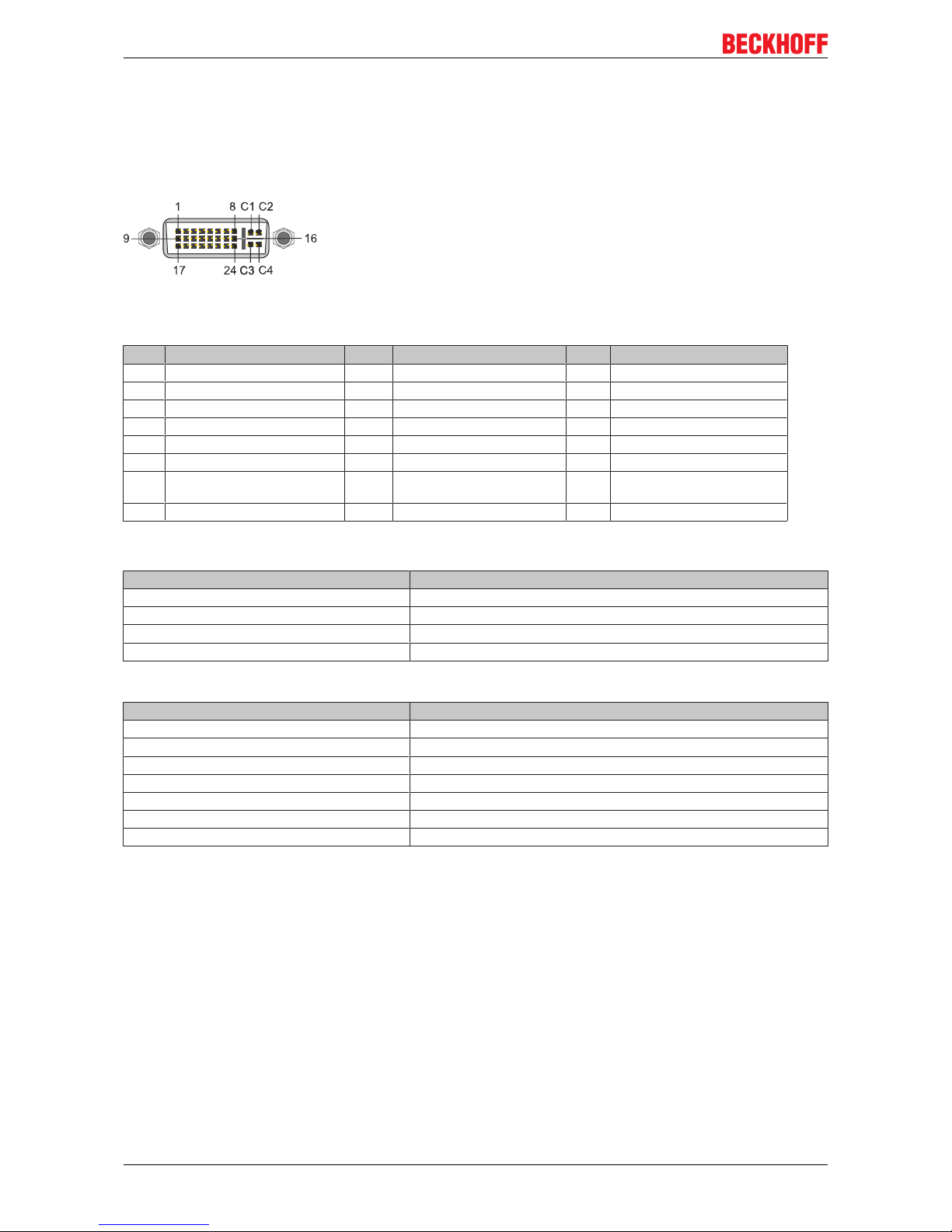
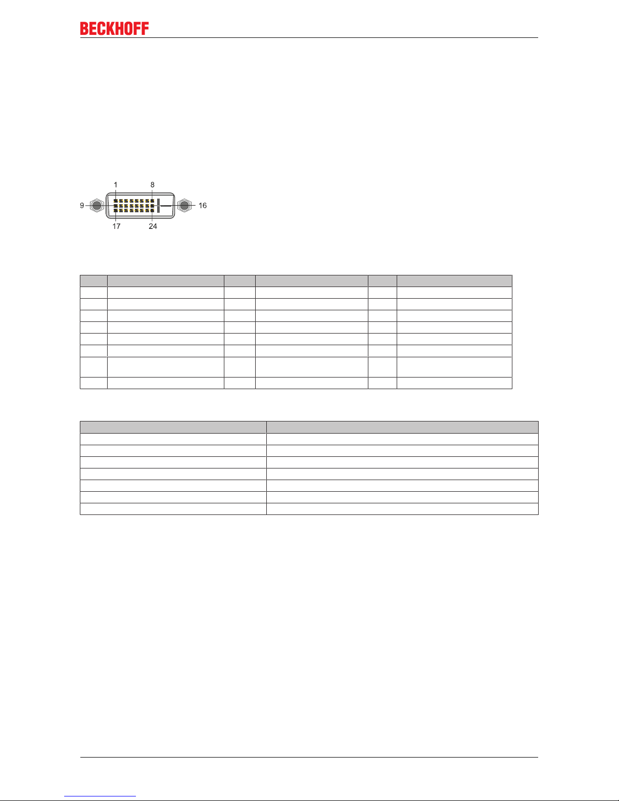
5.3 DVI-I (X200)
The DVI-I interface (X200) transfers digital data and is suitable for connection to digital or analog monitors.
The resolution at the display or the Beckhoff Control Panel depends on the distance from the display device.
The maximum distance is 5 m. Beckhoff offers various Panels with an integrated “DVI extension”. These
make a cable length of up to 50 meters possible.
Fig.8: DVI-I interface X200.
Table8: DVI-I interface X200, pin assignment.
Pin Assignment Pin Assignment Pin Assignment
1 TMDS Data 2- 9 TMDS Data 1- 17 TMDS Data 0-
2 TMDS Data 2+ 10 TMDS Data 1+ 18 TMDS Data 0+
3 TMDS Data 2/4 Shield 11 TMDS Data 1/3 Shield 19 TMDS Data 0/5 Shield
4 not connected 12 not connected 20 not connected
5 not connected 13 not connected 21 not connected
6 DDC Clock 14 + 5V Power 22 TMDS Clock Shield
7 DDC Data 15 Ground ( +5V, Analog H/V
Sync)
23 TMDS Clock +
8 Analog Vertical Sync 16 Hot Plug Detect 24 TMDA Clock -
Table9: DVI-I cross, pin assignment.
Pin Assignment
C1 Analog Red Video Out
C2 Analog Green Video Out
C3 Analog Blue Video Out
C4 Analog Horizontal Sync
Table10: DVI-I interface X200, resolution at the monitor.
Resolution in pixels Distance of the interface from the monitor
1920 x 1200 5 m
1920 x 1080 5 m
1600 x 1200 5 m
1280 x 1024 5 m
1024 x 768 5 m
800 x 600 5 m
640 x 480 5 m
The Embedded PC also supports higher resolutions, based on the DVI standard. A maximum resolution of
2560 x 1440 pixels can be set on the Embedded PC. Whether this resolution is achieved depends on the
monitor, the cable quality and the cable length.
Description of the interfaces
CX51x0 21Version: 1.9
5.4 Optional interfaces
5.4.1 DVI-D (N010)
The DVI-D interface (X300) transfers digital data and is suitable for connection to digital displays. If the
optional N010 interface (DVI-D interface) is used, the first DVI-I interface can be operated either in VGA
mode or in DVI mode. The resolution at the display or the Beckhoff Control Panel depends on the distance
from the display device. The maximum distance is 5 m. Beckhoff offers various Panels with an integrated
“DVI extension”. These make a cable length of up to 50 meters possible.
Fig.9: DVI-D interface X300.
Table11: DVI-D interface X300, pin assignment.
Pin Assignment Pin Assignment Pin Assignment
1 TMDS Data 2- 9 TMDS Data 1- 17 TMDS Data 0-
2 TMDS Data 2+ 10 TMDS Data 1+ 18 TMDS Data 0+
3 TMDS Data 2/4 Shield 11 TMDS Data 1/3 Shield 19 TMDS Data 0/5 Shield
4 not connected 12 not connected 20 not connected
5 not connected 13 not connected 21 not connected
6 DDC Clock 14 + 5V Power 22 TMDS Clock Shield
7 DDC Data 15 Ground ( +5V, Analog H/V
Sync)
23 TMDS Clock +
8 Analog Vertical Sync 16 Hot Plug Detect 24 TMDA Clock -
Table12: DVI-D interface X300, resolution at the monitor.
Resolution in pixels Distance of the interface from the monitor
1920 x 1200 5 m
1920 x 1080 5 m
1600 x 1200 5 m
1280 x 1024 5 m
1024 x 768 5 m
800 x 600 5 m
640 x 480 5 m
The Embedded PC also supports higher resolutions, based on the DVI standard. A maximum resolution of
2560 x 1440 pixels can be set on the Embedded PC. Whether this resolution is achieved depends on the
monitor, the cable quality and the cable length.
Description of the interfaces
CX51x022 Version: 1.9
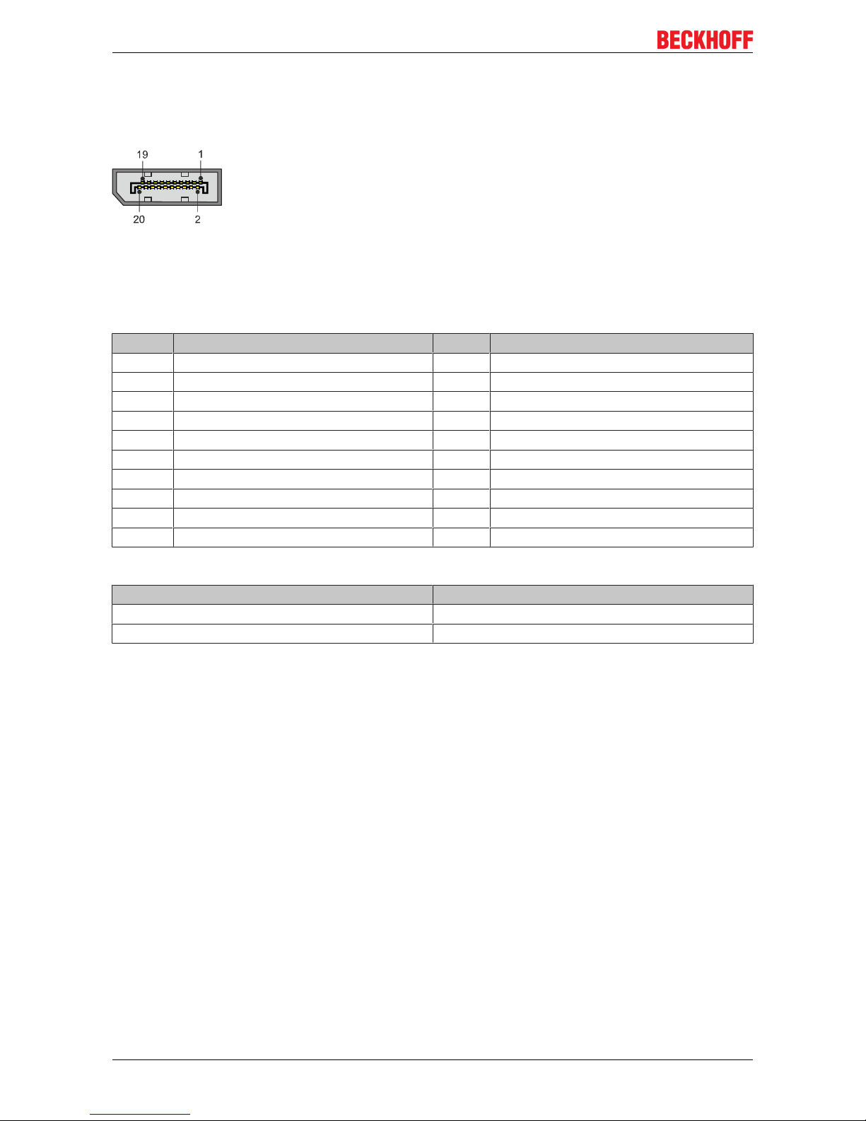
5.4.2 DisplayPort (N011)
The DisplayPort transfers image and audio signal at the same time and is therefore suitable for connecting
panels or monitors to the Embedded PC.
Fig.10: DisplayPort X300.
Version 1.1a of the DisplayPort (DisplayPort++) is installed on the Embedded PC. Adapters from DisplayPort
to DVI-D or DisplayPort to HDMI can be used to connect monitors without DisplayPort to the Embedded PC.
Table13: DisplayPort, pin assignment.
Pin Assignment Pin Assignment
1 LVDS lane 0+ 2 Ground
3 LVDS lane 0- 4 LVDS lane 1+
5 Ground 6 LVDS lane 1-
7 LVDS lane 2+ 8 Ground
9 LVDS lane 2- 10 LVDS lane 3+
11 Ground 12 LVDS lane 3-
13 Config 1 14 Config 2
15 AUX channel+ 16 Ground
17 AUX channel- 18 Hot-plug detection
19 Power supply: ground 20 Power supply: 3.3 V / 500 mA
Table14: DisplayPort X300, resolution at the monitor.
Interface Resolution in pixels
DisplayPort max. 2560 x 1600 @ 60 Hz
DisplayPort with adapter, DisplayPort to DVI-D max. 1600 x 1200 @ 60 Hz
Description of the interfaces
CX51x0 23Version: 1.9
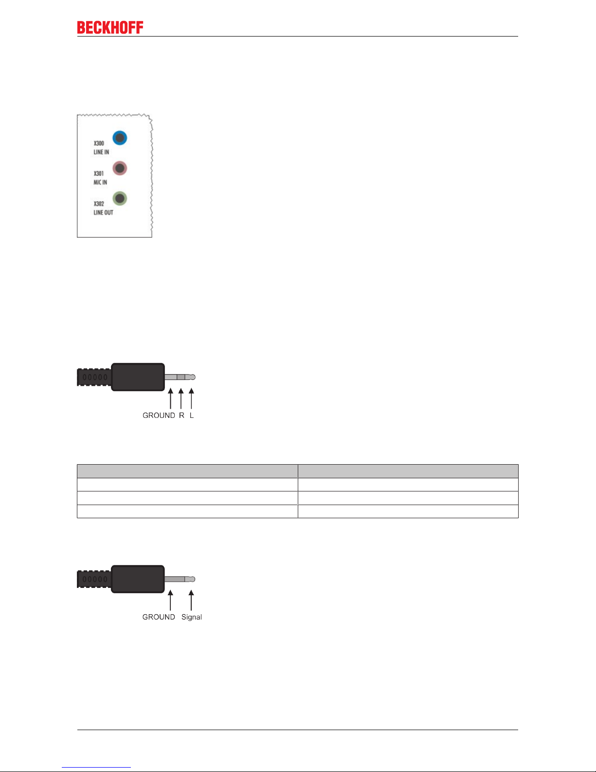
5.4.3 Audio interface (N020)
Two inputs are available: "LINE IN" (X300) and "MIC IN" (X301). The "LINE OUT" interface (X302) is
intended for audio signal output. The 3.5 mm sockets are designed for jack plugs. It can also be used for
connecting headphones with a maximum output of 200 mW.
Fig.11: Audio interface X300, X301, X302.
The audio interfaces are accessed via the operating system.
The audio interface operates in stereo mode as standard, using stereo outputs/inputs and a single-channel
input for the microphone. The inputs should be connected as indicated.
Line In / Line Out jack plugs
The left channel is transferred via the tip of the jack plug, the right channel via the first ring. The remainder of
the sleeve is used for earthing.
Fig.12: Line In / Line Out X300, X302 jack plugs.
Table15: Line In /Line Out jack plugs, pin assignment.
Signal Description
L Left channel
R Right channel
Ground Ground
Mic In jack plug
The only existing channel is transferred via the tip, the remainder of the sleeve is used for earthing.
Fig.13: Mic In X301 jack plug.
Description of the interfaces
CX51x024 Version: 1.9
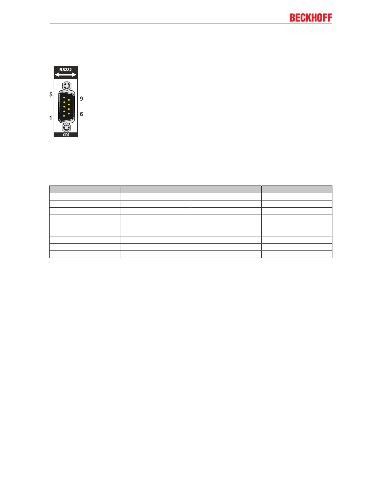
5.4.4 RS232 (N030)
The optional N030 interface provides an RS232 interface (X300). The RS232 interface is implemented on a
9-pin D-sub connector.
Fig.14: RS232 interface X300 with pin numbering.
The maximum baud rate on both channels is 115 kbit. The interface parameters are set via the operating
system or from the PLC program.
Table16: RS232 interface X300, pin assignment.
PIN Signal Type Description
1 DCD Signal in Data Carrier Detected
2 RxD Signal in Receive Data
3 TxD Signal out Transmit Data
4 DTR Signal out Data Terminal Ready
5 GND Ground Ground
6 DSR Signal in Dataset Ready
7 RTS Signal out Request to Send
8 CTS Signal in Clear to Send
9 RI Signal in Ring Indicator
Limited driver support
The driver manufacturer does not support all standard functions for the interface. As a result, some
applications may not run properly under Windows.
The following API and IOCTLs are not supported:
• SetupComm
• SetCommBreak
• ClearCommBreak
• EscapeCommFunction (no support for parameters SETBREAK and CLR-BREAK)
• IOCTL_SERIAL_XOFF_COUNTER
• IOCTL_SERIAL_LSRMST_INSERT
• IOCTL_SERIAL_SET_BREAK_ON
• IOCTL_SERIAL_SET_BREAK_OFF
Description of the interfaces
CX51x0 25Version: 1.9
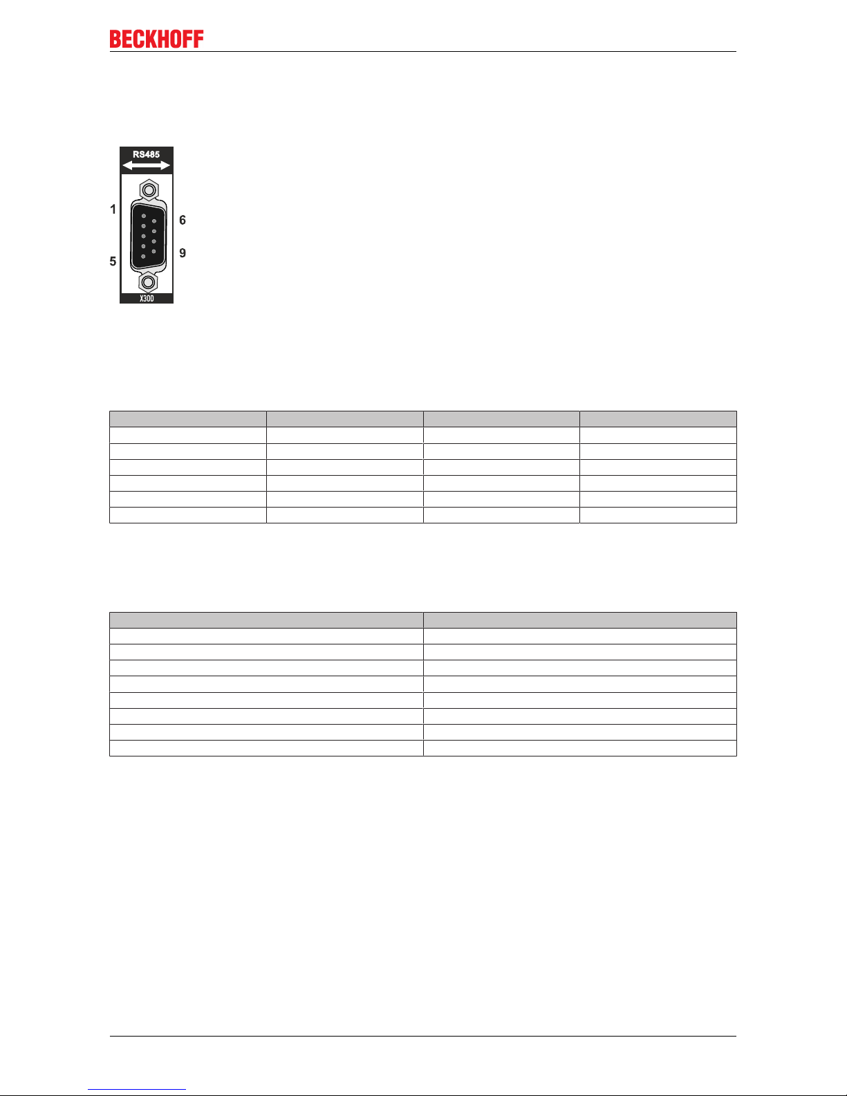
5.4.5 RS422/RS485 (N031)
The optional N031 interface provides an RS422 or RS485 interface (X300). The interface is implemented on
a 9-pin D-sub connector.
Fig.15: RS485 interface X300 with pin numbering.
The maximum baud rate on both channels is 115 kbit. The interface parameters are set via the operating
system or from the PLC program.
Table17: RS422/485 interface, pin assignment.
PIN Signal Type Description
2 TxD+ Data-Out + Transmit 422
3 RxD+ Data-In + Receive 422
5 GND Ground Ground
6 VCC VCC +5 V
7 TxD- Data-Out - Transmit 422
8 RxD- Data-In - Receive 422
For RS485 pins 2 and 3 (data +) must be connected, and pins 7 and 8 (data –).
By default the interface is parameterized as follows on delivery:
Table18: Default setting, RS485 without echo with end point (terminated).
Function Status
Echo on off
Echo off on
Auto send on on
Always send on off
Auto receive on on
Always receive on off
Term on on
Term on On
Other configurations for the RS485 interface
Other configurations for the RS485 interface can be ordered ex factory. The following options are available:
• N031-0001 RS485 with echo, end point (terminated).
• N031-0002 RS485 without echo, stub (without termination).
• N031-0003 RS485 with echo, stub (without termination).
• N031-0004 RS422 full duplex end point (terminated).
An RS485 interface cannot be configured retrospectively and must always be ordered ex factory as required.
Limited driver support
The driver manufacturer does not support all standard functions for the interface. As a result, some
applications may not run properly under Windows.
The following API and IOCTLs are not supported:

Description of the interfaces
CX51x026 Version: 1.9
• SetupComm
• SetCommBreak
• ClearCommBreak
• EscapeCommFunction (no support for parameters SETBREAK and CLR-BREAK)
• IOCTL_SERIAL_XOFF_COUNTER
• IOCTL_SERIAL_LSRMST_INSERT
• IOCTL_SERIAL_SET_BREAK_ON
• IOCTL_SERIAL_SET_BREAK_OFF
Description of the interfaces
CX51x0 27Version: 1.9
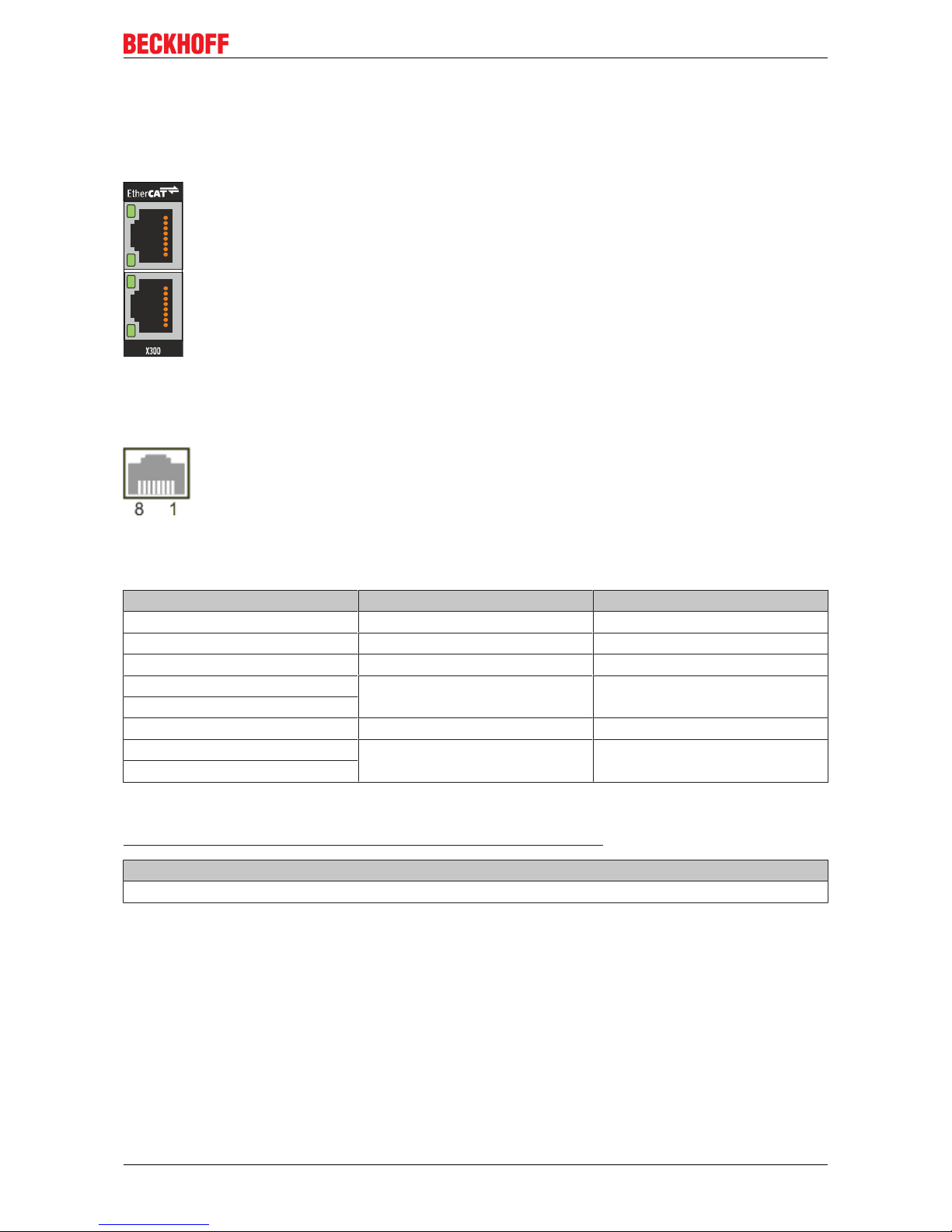
5.4.6 EtherCAT slave (B110)
The latest generation of Embedded PCs can be ordered ex factory with an EtherCAT slave interface (B110).
On the devices the optional B110 interface is referred to as X300.
Fig.16: EtherCAT slave interface X300.
The incoming EtherCAT signal is connected to the upper LAN interface. The lower LAN interface relays the
signal to other EtherCAT slave devices.
Fig.17: EtherCAT slave LAN interface, pin numbering.
Table19: EtherCAT slave interface X300, pin assignment.
PIN Signal Description
1 TD + Transmit +
2 TD - Transmit -
3 RD + Receive +
4 connected reserved
5
6 RD - Receive -
7 connected reserved
8
For the optional EtherCAT slave interface (B110), documentation with further information is available for
download from the Beckhoff website:
https://www.beckhoff.de/german/download/epc.htm?id=71003127100362
Document name
CXxxx0-B110 optional interface EtherCAT slave.
 Loading...