


Documentation
EL6900-FB, KL6904-FB
TwinCAT function blocks for TwinSAFE logic terminals
Version: 2.4.1
Date: 2015-03-11

Table of contents
Table of contents
1 |
Foreword |
5 |
||
|
1.1 |
Notes on the manual |
5 |
|
|
|
1.1.1 |
Disclaimer |
5 |
|
|
1.1.2 |
Brands |
5 |
|
|
1.1.3 |
Patents |
5 |
|
|
1.1.4 |
Copyright |
5 |
|
|
1.1.5 |
Delivery conditions |
5 |
|
1.2 |
Safety instructions |
6 |
|
|
|
1.2.1 |
Delivery state |
6 |
|
|
1.2.2 Operator's obligation to exercise diligence |
6 |
|
|
|
1.2.3 Description of safety symbols |
7 |
|
|
|
1.2.4 Origin of the document |
7 |
|
|
|
1.2.5 |
Documentation issue status |
8 |
2 |
System description |
9 |
||
|
2.1 |
TwinSAFE logic terminals EL6900/KL6904 |
9 |
|
|
|
2.1.1 |
TwinSAFE group |
9 |
|
|
2.1.2 |
TwinSAFE connection |
11 |
|
|
2.1.3 |
System diagnosis |
11 |
3 |
Function blocks |
17 |
||
|
3.1 |
The AND function block |
17 |
|
|
|
3.1.1 |
Functional description |
17 |
|
|
3.1.2 |
Signal description |
18 |
|
|
3.1.3 FB AND configuration in the TwinCAT System Manager |
20 |
|
|
3.2 |
The OR function block |
21 |
|
|
|
3.2.1 |
Functional description |
21 |
|
|
3.2.2 |
Signal description |
22 |
|
|
3.2.3 FB OR configuration in the TwinCAT System Manager |
24 |
|
|
3.3 |
The OPMODE function block |
25 |
|
|
|
3.3.1 |
Functional description |
25 |
|
|
3.3.2 |
Signal description |
26 |
|
|
3.3.3 FB OPMODE configuration in the TwinCAT System Manager |
29 |
|
|
3.4 |
The ESTOP function block |
30 |
|
|
|
3.4.1 |
Functional description |
30 |
|
|
3.4.2 |
Signal description |
31 |
|
|
3.4.3 FB ESTOP configuration in the TwinCAT System Manager |
33 |
|
|
3.5 |
The MON function block |
35 |
|
|
|
3.5.1 |
Functional description |
35 |
Function blocks for TwinSAFE logic terminals |
1 |
|||

Table of contents
3.5.2 |
Signal description |
37 |
3.5.3 |
FB MON configuration in the TwinCAT System Manager |
39 |
3.6 The DECOUPLE function block |
41 |
|
3.6.1 |
Functional description |
41 |
3.6.2 |
Signal description |
42 |
3.6.3 |
FB DECOUPLE configuration in the TwinCAT System Manager |
45 |
3.7 The TWO-HAND function block |
46 |
|
3.7.1 |
Functional description |
46 |
3.7.2 |
Signal description |
47 |
3.7.3 |
FB TWO-HAND configuration in the TwinCAT System Manager |
49 |
3.7.4 |
Examples of two-hand control types according to DIN EN 574 : 1996 |
50 |
3.8 The MUTING function block |
51 |
|
3.8.1 |
Functional description |
51 |
3.8.2 |
Signal description |
52 |
3.8.3 |
FB MUTING configuration in the TwinCAT System Manager |
55 |
3.9 The EDM function block |
61 |
|
3.9.1 |
Functional description |
61 |
3.9.2 |
Signal description |
62 |
3.9.3 |
FB EDM configuration in the TwinCAT System Manager |
63 |
3.10 The RS function block |
64 |
|
3.10.1 |
Functional description |
64 |
3.10.2 |
Signal description |
65 |
3.10.3 |
FB RS configuration in the TwinCAT System Manager |
66 |
3.11 The SR function block |
67 |
|
3.11.1 |
Functional description |
67 |
3.11.2 |
Signal description |
68 |
3.11.3 |
FB SR configuration in the TwinCAT System Manager |
69 |
3.12 The TON function block |
70 |
|
3.12.1 |
Functional description |
70 |
3.12.2 |
Signal description |
71 |
3.12.3 |
FB TON configuration in the TwinCAT System Manager |
72 |
3.13 The TOF function block |
73 |
|
3.13.1 |
Functional description |
73 |
3.13.2 |
Signal description |
74 |
3.13.3 |
FB TOF configuration in the TwinCAT System Manager |
75 |
3.14 The CONNECTION SHUTDOWN function block |
76 |
|
3.14.1 |
Functional description |
76 |
3.14.2 |
Signal description |
78 |
3.14.3 |
FB ConnectionShutdown configuration in the TwinCAT System Manager |
80 |
2 |
Function blocks for TwinSAFE logic terminals |
|

Table of contents
4 Appendix |
81 |
|
4.1 Beckhoff Support and Service |
81 |
|
4.1.1 |
Beckhoff branches and partner companies Beckhoff Support |
81 |
4.1.2 |
Beckhoff company headquarters |
81 |
Function blocks for TwinSAFE logic terminals |
3 |

Foreword
1 Foreword
1.1 Notes on the manual
This description is only intended for the use of trained specialists in control and automation technology familiar with the applicable national standards. It is essential that the following notes and explanations are followed when installing and commissioning these components.
The responsible staff must ensure that the application or use of the products described satisfy all the safety requirements, including all the relevant laws, regulations, guidelines and standards.
1.1.1 Disclaimer
This documentation has been prepared with care. The products described are, however, constantly under development. For this reason, the documentation may not always have been fully checked for consistency with the performance data, standards or other characteristics described.
If it should contain technical or editorial errors, we reserve the right to make changes at any time and without notice.
No claims for the modification of products that have already been supplied may be made on the basis of the data, diagrams and descriptions in this documentation.
1.1.2 Brands
Beckhoff®, TwinCAT®, EtherCAT®, Safety over EtherCAT®, TwinSAFE® and XFC® are registered trademarks of and licensed by Beckhoff Automation GmbH.
The use by third parties of other brand names or trademarks contained in this documentation may lead to an infringement of the rights of the respective trademark owner.
1.1.3 Patents
The EtherCAT technology is patent protected, in particular by the following applications and patents: EP1590927, EP1789857, DE102004044764, DE102007017835 with the corresponding applications and registrations in various other countries.
The TwinCAT technology is patent protected, in particular by the following applications and patents: EP0851348, US6167425 with the corresponding applications and registrations in various other countries.
1.1.4 Copyright
© Beckhoff Automation GmbH & Co. KG.
The copying, distribution and utilization of this document as well as the communication of its contents to others without express authorization is prohibited. Offenders shall be held liable for damages. All rights conferred by patent grant or registration of a utility model or registered design are reserved.
1.1.5 Delivery conditions
In addition, the general delivery conditions of the company Beckhoff Automation GmbH & Co. KG apply.
Function blocks for TwinSAFE logic terminals |
5 |

Foreword
1.2 Safety instructions
1.2.1Delivery state
All the components are supplied in particular hardware and software configurations appropriate for the application. Modifications to hardware or software configurations other than those described in the documentation are not permitted, and nullify the liability of Beckhoff Automation GmbH & Co. KG.
1.2.2Operator's obligation to exercise diligence
The operator must ensure that
∙the TwinSAFE products are only used as intended (see section Product description);
∙the TwinSAFE products are only operated in sound condition and in working order.
∙the TwinSAFE products are operated only by suitably qualified and authorized personnel.
∙the personnel is instructed regularly about relevant occupational safety and environmental protection aspects, and is familiar with the operating instructions and in particular the safety instructions contained herein.
∙the operating instructions are in good condition and complete, and always available for reference at the location where the TwinSAFE products are used.
∙none of the safety and warning notes attached to the TwinSAFE products are removed, and all notes remain legible.
6 |
Function blocks for TwinSAFE logic terminals |
Foreword
1.2.3Description of safety symbols
The following safety symbols are used in these operating instructions. They are intended to alert the reader to the associated safety instructions.
|
Serious risk of injury! |
|
DANGER |
Failure to follow the safety instructions associated with this symbol directly endangers |
|
the life and health of persons. |
||
|
||
|
|
|
|
Risk of injury! |
|
WARNING |
Failure to follow the safety instructions associated with this symbol endangers the life |
|
and health of persons. |
||
|
||
|
|
|
|
Personal injuries! |
|
CAUTION |
Failure to follow the safety instructions associated with this symbol can lead to injuries |
|
to persons. |
||
|
||
|
|
|
|
Damage to the environment or devices |
|
Attention |
Failure to follow the instructions associated with this symbol can lead to damage to the |
|
environment or equipment. |
||
|
Tip or pointer
This symbol indicates information that contributes to better understanding.
Note
1.2.4 Origin of the document
This documentation was originally written in German. All other languages are derived from the German original.
Function blocks for TwinSAFE logic terminals |
7 |

Foreword
1.2.5 Documentation issue status
Version |
Comment |
|
2.4.1 |
∙ |
Markings removed |
|
|
|
2.4.0 |
∙ |
Company address changed |
|
|
|
2.3.0 |
∙ Document origin and versions added |
|
|
∙ EDM extended with standard In |
|
|
∙ MUTING status information expanded |
|
|
∙ Two-hand diagnostic information expanded |
|
|
|
|
2.2.0 |
∙ TwinSAFE connection info data expanded |
|
|
∙ FB ESTOP info data expanded |
|
|
|
|
2.1.0 |
∙ FB OPMODE description expanded |
|
|
∙ |
Service/support information modified |
|
|
|
2.0.0 |
∙ |
EL6900 blocks added |
|
|
|
1.1.1 |
∙ Corrections during the translation into English |
|
|
|
|
1.1.0 |
∙ Amendments in the application examples |
|
|
|
|
1.0.0 |
∙ |
First released version |
|
|
|
8 |
Function blocks for TwinSAFE logic terminals |
System description
2 System description
The TwinSAFE system consists of safe inputs (EL/KL1904), safe outputs (EL/KL2904) and logic modules (KL6904/EL6900). The TwinSAFE logic terminal (KL6904/EL6900) contains function blocks, which can be parameterized and connected to each other and form the safety-related logic. Free programming is not possible. In addition to the non-safety-related logic configuration a fieldbus configuration is required for mapping the TwinSAFE data packets. These functions are realized via the TwinCAT System Manager. The safety-related TwinSAFE Verifier, which is available at the moment as a separate installation, deals with the loading and testing of the TwinSAFE project onto the EL6900/KL6904.
The TwinSAFE logic terminal can communicate, via the fieldbus-independent and certified TwinSAFEprotocol with safe input and output terminals, and also via further logic terminals. The TwinSAFE protocol is a Safety over EtherCAT (FSoE) protocol with one byte of safe user data. It is openly available via the EtherCAT Technology Group (www.ethercat.org).
2.1 TwinSAFE logic terminals EL6900/KL6904
The configuration of a TwinSAFE logic terminal consists of function blocks that are consolidated into one or several TwinSAFE groups. TwinSAFE groups can be started and stopped independently of each other.
The execution sequence of the function blocks corresponds to the TwinCAT System Managers project structure sequence illustrated. This sequence can be changed in the System Manager by Drag’n Drop.
The function blocks have parameters which must be configured by the user.
The inputs and outputs of the function blocks are assigned to the inputs and outputs of the TwinSAFE terminals, to other function blocks or to the input and output variable of the standard PLC by the user.
A TwinSAFE connection involves unambiguous assignment of a TwinSAFE device (EL/KL1904, EL/KL2904, EL6900/KL6904) to TwinSAFE group. Only function blocks which belong to this TwinSAFE group can be linked with the input and outputs of an assigned TwinSAFE connection. The DECOUPLE block can be used if it is necessary for other groups to access the inputs and outputs (see chapter 3.6).
Errors of the TwinSAFE communication within the TwinSAFE group and errors within a function block affect the complete TwinSAFE group. The TwinSAFE group then stops all associated function blocks, which then switch their outputs into a safe state.
Errors in the TwinSAFE Logic result in it switching off completely.
2.1.1TwinSAFE group
The function blocks are assigned to TwinSAFE groups. These have a characteristic that results in the return of all group outputs to a safe state (a safe state is always a wattless state at the output, corresponding to a logical 0) such as, in case of a communication error of an assigned TwinSAFE connection, in case of an error in assigned function blocks (e.g. excessive discrepancy time) or an error in the local assigned outputs. I.e. the TwinSAFE connection data and thus TwinSAFE input or output terminal are always exactly assigned to a TwinSAFE group.
A communication error is displayed on the output (COM ERR) of the TwinSAFE group and acknowledged on the input (ERR ACK). A function block error is displayed on the output (FB ERR) and acknowledged on the same input (ERR ACK) as the communication error. An error on the local outputs (only KL6904) is displayed on the third output (OUT ERR) and once again acknowledged (ERR_ACK) on the same input. The safe state of the TwinSAFE group outputs is removed once the error is no longer present and has been acknowledged.
The error acknowledgement is not carried out automatically, i.e. the "ERR ACK" input must always be
Function blocks for TwinSAFE logic terminals |
9 |

System description
linked.
Apart from this the TwinSAFE group has an input (RUN), with which the processing of the assigned function blocks can be stopped and started. All TwinSAFE group assigned outputs are in a safe state when stopped.
2.1.1.1TwinSAFE group inputs and outputs
Table 2-1: TwinSAFE group inputs
Name |
Permitted type |
Description |
RUN |
FB-Out |
TRUE: |
|
Standard-In |
The function blocks assigned to the TwinSAFE group are executed |
|
|
FALSE: |
|
|
All assigned function blocks of the TwinSAFE group are at a STOP |
|
|
state and thus all associated outputs are in a safe state |
|
|
When the input is not linked it is in the TRUE state |
|
|
|
ERR ACK |
FB-Out |
All pending errors in the assigned function blocks and in the |
|
Standard-In |
TwinSAFE connections are acknowledged by the FALSE->TRUE- |
|
|
>FALSE signal sequence. |
|
|
|
Table 2-2: TwinSAFE group outputs |
||
|
|
|
Name |
Permitted type |
Description |
FB ERR |
TwinSAFE-Out |
TRUE: |
|
FB-In |
At least one assigned function block has an error |
|
Standard-Out |
FALSE: |
|
Local-Out |
All assigned function blocks have no errors |
|
|
|
COM ERR |
TwinSAFE-Out |
TRUE: |
|
FB-In |
At least one TwinSAFE connection of TwinSAFE group has an error |
|
Standard-Out |
FALSE: |
|
Local-Out |
All TwinSAFE connections of the TwinSAFE group have no errors |
|
|
|
OUT ERR |
TwinSAFE-Out |
TRUE: |
|
FB-In |
At least one local output assigned to the TwinSAFE group has an |
|
Standard-Out |
error |
|
Local-Out |
FALSE: |
|
|
All of the local outputs assigned to the TwinSAFE group have no |
|
|
errors |
|
|
Always FALSE for EL6900, since the device has no local outputs. |
|
|
|
10 |
Function blocks for TwinSAFE logic terminals |
System description
2.1.2TwinSAFE connection
Each safe communication path between the TwinSAFE logic and TwinSAFE inputs, TwinSAFE outputs or other TwinSAFE logic terminals are referred to as TwinSAFE connection.
A communication partner is thus always the TwinSAFE master, the other the TwinSAFE slave. The TwinSAFE logic is in a TwinSAFE connection to a TwinSAFE input or TwinSAFE output is always TwinSAFE master. The TwinSAFE connection to another TwinSAFE logic can be TwinSAFE slave on the other hand, whereby the TwinCAT System Manager automatically defines this assignment.
Both the TwinSAFE master and the TwinSAFE slave have a FSoE (Safety over EtherCAT) address that can be set on the respective TwinSAFE terminal via a DIP switch in order to ensure that any mix-up of the TwinSAFE data packets is always detected. These FSoE addresses are checked within the TwinSAFE communication and must be unambiguous in the control system. The TwinSAFE Verifier for each TwinSAFE logic terminal checks that. The TwinSAFE logic control system may contain several TwinSAFE logic terminals, although the TwinSAFE Verifier can only be active for one TwinSAFE logic terminal at a time. The user must therefore ensure that multiple allocation of FSoE addresses is avoided.
For each TwinSAFE connection a watchdog time and the corresponding FSoE address for the communication devices can be set. In addition there is a possibility to adjust the SIL level, however this setting is not supported at the moment and has no effects on the safety behavior of the system. In another configuration option a module error in the TwinSAFE communication partner can be set to trigger a communication error in the TwinSAFE group.
2.1.3System diagnosis
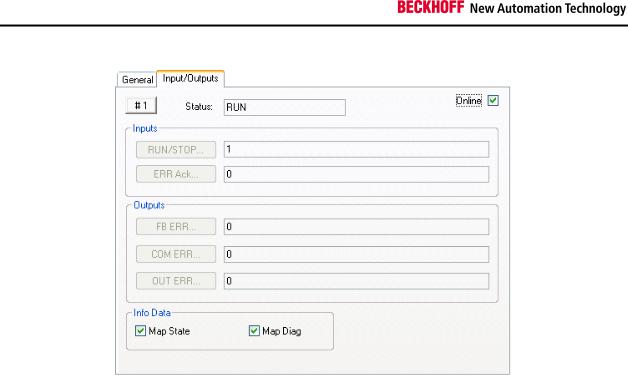
The states of the TwinSAFE groups, FBs and connections can be checked in the System Manager. The diagnostic information can be copied into the cyclic process image.
TwinSAFE groups have inputs and outputs of associated Screenshots assigned offline and which can be considered online.
If the checkboxes ‘Map State’ and ‘Map Diag’ are set, the state and diagnostic data for the group are copied into the cyclic process image and can be linked directly with PLC variables. The diagnostic data are currently always 0.
KL6904
With the KL6904 copying of the diagnostic information to the cyclic process image is Note only possible to a limited extent. The checkboxes ‘Map State’ and ‘Map Diag’ are not
available.
Function blocks for TwinSAFE logic terminals |
11 |
System description
|
|
Figure 2-1: Inputs/Outputs |
Table 2-3: Status information |
||
|
|
|
Value |
Status |
Description |
1 |
RUN |
All function blocks and TwinSAFE connections assigned to the TwinSAFE |
|
|
group operate properly, and all TwinSAFE connections assigned to the |
|
|
TwinSAFE group are up and running |
|
|
|
2 |
STOP |
State after initialization |
|
|
|
3 |
SAFE |
All function blocks and TwinSAFE connections assigned to the TwinSAFE |
|
|
group operate properly, and at least one of the TwinSAFE connections |
|
|
assigned to the TwinSAFE group is not yet up and running |
|
|
|
4 |
ERROR |
At least one assigned function block or one assigned TwinSAFE connection |
|
|
has reported an error |
|
|
|
5 |
RESET |
A positive edge (FALSE->TRUE) for acknowledgement of a function block |
|
|
or a TwinSAFE connection error was detected on the ERR_ACK input. The |
|
|
system is waiting for the negative edge of the ERR_ACK input |
|
|
|
12 |
Function blocks for TwinSAFE logic terminals |

System description
Figure 2-2: Inputs/Outputs
The status of TwinSAFE FBs is displayed on online summary. The current status data are read from the EL6900/KL6904 via a manual refresh.
Figure 2-3: Function Block List
If the checkboxes ‘Map State’ and ‘Map Diag’ for the individual TwinSAFE FBs are set, the status and diagnostic data for the FBs are copied into the cyclic process image and can be linked directly with PLC variables. The description of the status and diagnostic values can be found under the respective FBs.
Function blocks for TwinSAFE logic terminals |
13 |
System description
KL6904
With the KL6904 copying of the diagnostic information to the cyclic process image is Note only possible to a limited extent. The checkboxes ‘Map State’ and ‘Map Diag’ are not
available.
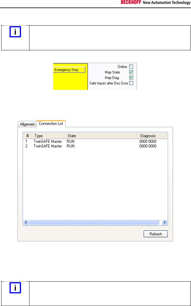
Figure 2-4: Emergency Stop
The TwinSAFE connections status is displayed on the TwinSAFE connection list summary under the "Connection List" tab. Diagnostics bits are also set in addition to the status.
Figure 2-5: Connection List
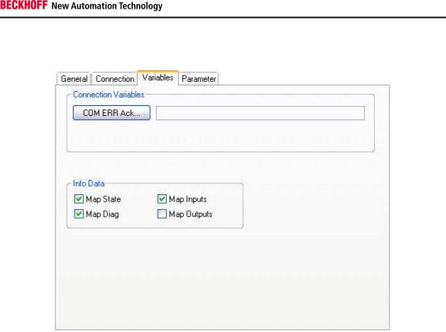
If the checkboxes ‘Map State’ and ‘Map Diag’ for the individual TwinSAFE connections are set, the status and diagnostic data for the connections are copied into the cyclic process image and can be linked directly with PLC variables. In addition, the safe inputs and outputs can be copied into the cyclic process image and used for diagnostic purposes.
KL6904
With the KL6904 copying of the diagnostic information to the cyclic process image is Note only possible to a limited extent. The checkboxes ‘Map State’, ‘Map Diag’‚ ‘Map Inputs’
and ‘Map Outputs’ are not available. The button “Com Err Ack” is also not available.
14 |
Function blocks for TwinSAFE logic terminals |
System description
Figure 2-6: Variables
Table 2-4: Diagnostic information for a connection
Value |
Description |
xxxx 0001 |
Invalid command |
|
|
xxxx 0010 |
Unknown command |
|
|
xxxx 0011 |
Invalid connection ID |
|
|
xxxx 0100 |
Invalid CRC |
|
|
xxxx 0101 |
Watchdog time elapsed |
|
|
xxxx 0110 |
Invalid FSoE address |
|
|
xxxx 0111 |
Invalid data |
|
|
xxxx 1000 |
Invalid communication parameter length |
|
|
xxxx 1001 |
Invalid communication parameters |
|
|
xxxx 1010 |
Invalid user parameter length |
|
|
xxxx 1011 |
Invalid user parameters |
|
|
xxxx 1100 |
FSoE master reset |
|
|
xxxx 1101 |
Module error detected on slave, with option "Module error is ComError" activated |
|
|
xxxx 1110 |
Module error detected on EL290x, with option "Error acknowledge active" activated |
|
|
xxxx 1111 |
Slave not yet started, or unexpected error argument |
|
|
xxx1 xxxx |
FSoE slave error detected |
|
|
xx1x xxxx |
FSoE slave reports Failsafe Value active |
|
|
x1xx xxxx |
StartUp |
|
|
1xxx xxxx |
FSoE master reports Failsafe Value active |
|
|
Function blocks for TwinSAFE logic terminals |
15 |

System description
Table 2-5: Status information for a connection
Value |
Description |
100 (0x64) |
Reset state: |
|
The reset state is used to re-initialize the Safety over EtherCAT connection after |
|
the power-on or a Safety over EtherCAT communication error. |
|
|
101 (0x65) |
Session state: |
|
During the transition to or in the session state a session ID is transferred from |
|
the Safety over EtherCAT master to the Safety over EtherCAT slave, which in |
|
turn responds with its own session ID. |
|
|
102 (0x66) |
Connection state: |
|
In the connection state a connection ID is transferred from the Safety over |
|
EtherCAT master to the Safety over EtherCAT slave. |
|
|
103 (0x67) |
Parameter state: |
|
In the parameter state safe communicationand device-specific application |
|
parameters are transferred. |
|
|
104 (0x68) |
Data state: |
|
In the data state Safety over EtherCAT cycles are transferred until either a |
|
communication error occurs or a Safety over EtherCAT node is stopped locally. |
|
|
105 (0x69) |
Shutdown state: |
|
In the shutdown state the connection was shut down by one of the |
|
communication partners. |
|
|
Further information can be found in the Safety over EtherCAT specification.
16 |
Function blocks for TwinSAFE logic terminals |
Function blocks
3 Function blocks
The function blocks have a specified functionality that still must be configured via a parameter. The inputs or outputs of a function block can be inputs or outputs of a local process image, but function block outputs and inputs can be can be linked.
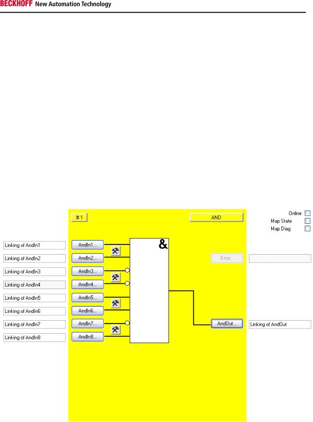
3.1 The AND function block
3.1.1Functional description
With the FB AND several input signals can be linked via AND to one output signal. In addition each input can still be set even if the input signal is a normally closed contact (Break contact) or normally open contact (Make contact). A normally open contact means that the corresponding input signal is negated, before it affects the AND.
The AndIn1 input differs from the AndIn2-AndIn8 inputs in such a way that it can also be linked with a standard input. This makes it possible to switch off a safe output using a standard signal. Outputs cannot be switched on but only released using a standard signal, since at least two inputs must always be linked for FB AND (and the second input is a safe one, which prevents switching on).
Figure 3-1: AND function block
Function blocks for TwinSAFE logic terminals |
17 |

Function blocks
3.1.2Signal description
Table 3-1: FB AND inputs
Name |
|
Permitted type |
Description |
AndIn1 |
|
TwinSAFE-In |
1st input channel |
|
|
FB-Out |
|
|
|
Standard-In |
|
|
|
|
|
AndIn2 |
|
TwinSAFE-In |
2nd input channel |
|
|
FB-Out |
|
|
|
|
|
AndIn3 |
|
TwinSAFE-In |
3rd input channel |
|
|
FB-Out |
|
|
|
|
|
AndIn4 |
|
TwinSAFE-In |
4th input channel |
|
|
FB-Out |
|
|
|
|
|
AndIn5 |
|
TwinSAFE-In |
5th input channel |
|
|
FB-Out |
|
|
|
|
|
AndIn6 |
|
TwinSAFE-In |
6th input channel |
|
|
FB-Out |
|
|
|
|
|
AndIn7 |
|
TwinSAFE-In |
7th input channel |
|
|
FB-Out |
|
|
|
|
|
AndIn8 |
|
TwinSAFE-In |
8th input channel |
|
|
FB-Out |
|
|
|
|
|
Table 3-2: FB AND outputs |
|
||
|
|
|
|
Name |
|
Permitted type |
Description |
AndOut |
|
TwinSAFE-Out |
Output channel |
|
|
FB-In |
|
|
|
Standard-Out |
|
|
|
Local-Out |
|
|
|
|
|
Table 3-3: FB AND input and output types |
|||
|
|
|
|
Type |
|
Description |
|
TwinSAFE-In |
|
TwinSAFE input at an EL1904/KL1904 |
|
|
|
|
|
Standard-In |
|
Standard PLC variable (output in the PLC %Q*) |
|
|
|
|
|
FB-Out |
|
TwinSAFE FB output |
|
|
|
||
TwinSAFE-Out |
TwinSAFE output at an EL2904/KL2904 |
||
|
|
|
|
Standard-Out |
|
Standard PLC variable (input in the PLC %I*) |
|
|
|
|
|
FB-In |
|
TwinSAFE FB input |
|
|
|
|
|
Local-Out |
|
TwinSAFE output at the KL6904 (not available for EL6900) |
|
|
|
|
|
18 |
Function blocks for TwinSAFE logic terminals |
Function blocks
3.1.2.1Diagnostic and status information for FB AND
Table 3-4: Diagnostic information (16-bit value)
Index |
Description |
0-15 |
always 0 |
|
|
Table 3-5: Status information (8-bit value)
Index |
Description |
0 |
undefined |
|
|
1 |
RUN |
|
|
2 |
STOP |
|
|
3 |
SAFE |
|
|
KL6904
The checkboxes ‘Map State’ and ‘Map Diag’ are notvailable for the KL6904.
Note
Function blocks for TwinSAFE logic terminals |
19 |
Function blocks
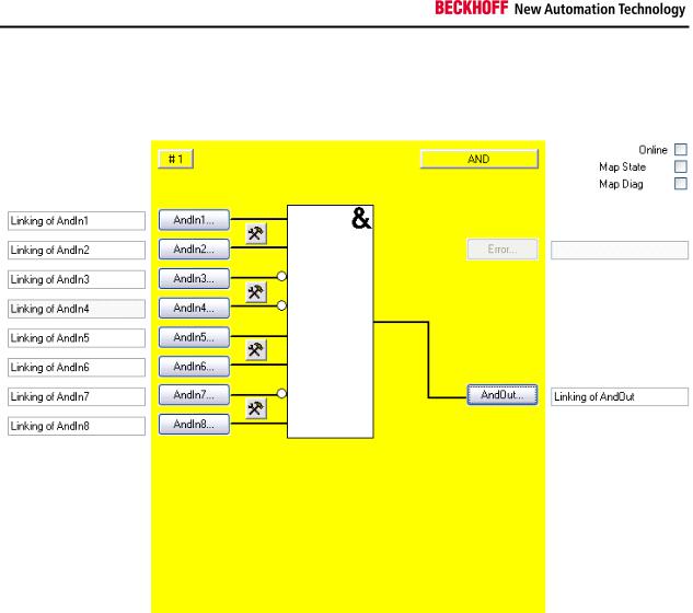
3.1.3FB AND configuration in the TwinCAT System Manager
Figure 3-2: FB AND configuration
Their characteristics are configured with the setting buttons on the right near the two AndIn inputs, whereby the inputs are always single-channel ones. A discrepancy monitoring cannot be used for the AND.
The 'AndIn(x)' buttons can only be selected when the corresponding input has been activated. All inputs are deactivated in the default setting.
The FB AND input variables are linked using the 'AndIn(x)' buttons.
The output variable of the FB AND are linked using the 'AndOut' button.
The ‘MapState’ and ‘MapDiag’ checkboxes are used tospecify which FB diagnostic functions are mapped to the cyclic process image.
The FB AND does not supply any error information and therefore the error button is basically deactivated.
20 |
Function blocks for TwinSAFE logic terminals |
Function blocks
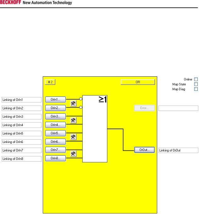
3.2 The OR function block
3.2.1Functional description
With the FB OR several input signals can be linked via OR to one output signal. In addition each input can still be set even if the input signal is a normally closed contact (Break contact) or normally open contact (Make contact). A normally open contact means that the corresponding input signal is negated, before it affects the OR.
Figure 3-3: OR function block
Function blocks for TwinSAFE logic terminals |
21 |

Function blocks
3.2.2Signal description
Table 3-6: FB OR inputs
Name |
Permitted type |
Description |
OrIn1 |
TwinSAFE-In |
1st input channel |
|
FB-Out |
|
|
|
|
OrIn2 |
TwinSAFE-In |
2nd input channel |
|
FB-Out |
|
|
|
|
OrIn3 |
TwinSAFE-In |
3rd input channel |
|
FB-Out |
|
|
|
|
OrIn4 |
TwinSAFE-In |
4th input channel |
|
FB-Out |
|
|
|
|
OrIn5 |
TwinSAFE-In |
5th input channel |
|
FB-Out |
|
|
|
|
OrIn6 |
TwinSAFE-In |
6th input channel |
|
FB-Out |
|
|
|
|
OrIn7 |
TwinSAFE-In |
7th input channel |
|
FB-Out |
|
|
|
|
OrIn8 |
TwinSAFE-In |
8th input channel |
|
FB-Out |
|
|
|
|
Table 3-7: FB OR outputs |
|
|
|
|
|
Name |
Permitted type |
Description |
OrOut |
TwinSAFE-Out |
Output channel |
|
FB-In |
|
|
Standard-Out |
|
|
Local-Out |
|
|
|
|
Table 3-8: FB OR input and output types |
||
|
|
|
Type |
|
Description |
TwinSAFE-In |
|
TwinSAFE input at an EL1904/KL1904 |
|
|
|
Standard-In |
|
Standard PLC variable (output in the PLC %Q*) |
|
|
|
FB-Out |
|
TwinSAFE FB output |
|
|
|
TwinSAFE-Out |
TwinSAFE output at an EL2904/KL2904 |
|
|
|
|
Standard-Out |
|
Standard PLC variable (input in the PLC %I*) |
|
|
|
FB-In |
|
TwinSAFE FB input |
|
|
|
Local-Out |
|
TwinSAFE output at the KL6904 (not available for EL6900) |
|
|
|
22 |
Function blocks for TwinSAFE logic terminals |
Function blocks
3.2.2.1Diagnostic and status information for FB OR
Table 3-9: Diagnostic information (16-bit value)
Index |
Description |
0-15 |
always 0 |
|
|
Table 3-10: Status information (8-bit value)
Index |
Description |
0 |
undefined |
|
|
1 |
RUN |
|
|
2 |
STOP |
|
|
3 |
SAFE |
|
|
KL6904
The checkboxes ‘Map State’ and ‘Map Diag’ are notvailable for the KL6904.
Note
Function blocks for TwinSAFE logic terminals |
23 |
 Loading...