


Operating instructions for
EL1904
TwinSAFE input terminal with 4 fail-safe inputs
Version: 1.5.1
Date: 30.01.2015

|
|
|
Table of contents |
|
|
|
|||
Table of contents |
|
|||
1 |
Foreword |
|
3 |
|
|
1.1 |
Notes on the manual |
3 |
|
|
|
1.1.1 |
Disclaimer |
3 |
|
|
1.1.2 |
Brands |
3 |
|
|
1.1.3 |
Patents |
3 |
|
|
1.1.4 |
Copyright |
3 |
|
|
1.1.5 |
Delivery conditions |
3 |
|
1.2 |
Safety instructions |
4 |
|
|
|
1.2.1 |
Delivery state |
4 |
|
|
1.2.2 Operator's obligation to exercise diligence |
4 |
|
|
|
1.2.3 Description of safety symbols |
5 |
|
|
|
1.2.4 Origin of the document |
5 |
|
|
|
1.2.5 |
Documentation issue status |
6 |
2 |
System description |
7 |
||
|
2.1 |
The Beckhoff Bus Terminal system |
7 |
|
|
|
2.1.1 |
Bus Coupler |
8 |
|
|
2.1.2 |
Bus Terminals |
9 |
|
|
2.1.3 |
E-bus |
9 |
|
|
2.1.4 |
Power contacts |
9 |
|
2.2 |
TwinSAFE |
10 |
|
|
|
2.2.1 The I/O construction kit is extended safely |
10 |
|
|
|
2.2.2 |
Safety concept |
10 |
|
|
2.2.3 EL1904, EL2904 – Bus Terminals with 4 fail-safe inputs or outputs |
11 |
|
|
|
2.2.4 |
EL6900 - TwinSAFE logic terminal |
11 |
|
|
2.2.5 The fail-safe principle (Fail Stop) |
11 |
|
3 |
Product description |
12 |
||
|
3.1 |
General description |
12 |
|
|
3.2 |
Intended use |
13 |
|
|
3.3 |
Technical data |
14 |
|
|
3.4 |
Safety parameters |
15 |
|
|
3.5 |
Characteristic curve of the inputs |
15 |
|
|
3.6 |
Dimensions |
16 |
|
|
3.7 |
Block diagram EL1904 |
17 |
|
EL1904 |
1 |

Table of contents
4 |
Operation |
18 |
||
|
4.1 |
Installation |
18 |
|
|
|
4.1.1 |
Safety instructions |
18 |
|
|
4.1.2 |
Transport / storage |
18 |
|
|
4.1.3 |
Mechanical installation |
19 |
|
|
4.1.4 |
Electrical installation |
22 |
|
|
4.1.5 |
Tested devices |
27 |
|
4.2 |
Operation in potentially explosive atmospheres (ATEX) |
28 |
|
|
|
4.2.1 |
Special conditions |
28 |
|
|
4.2.2 |
Identification |
29 |
|
|
4.2.3 Date code and serial number |
29 |
|
|
|
4.2.4 |
Further ATEX documentation |
29 |
|
4.3 |
Configuration of the EL1904 in the TwinCAT System Manager |
30 |
|
|
|
4.3.1 Inserting a Beckhoff Bus Coupler |
30 |
|
|
|
4.3.2 Inserting a Beckhoff Bus Terminal |
30 |
|
|
|
4.3.3 |
Inserting an EL1904 |
30 |
|
|
4.3.4 Address settings on the TwinSAFE terminals |
31 |
|
|
|
4.3.5 Entering a TwinSAFE address and parameters in the System Manager |
32 |
|
|
4.4 |
Diagnostics |
35 |
|
|
|
4.4.1 |
Diagnostic LEDs |
35 |
|
|
4.4.2 |
Diagnostic objects |
37 |
|
4.5 |
Maintenance |
38 |
|
|
|
4.5.1 |
Cleaning |
38 |
|
|
4.5.2 |
Service life |
38 |
|
4.6 |
Decommissioning |
39 |
|
|
|
4.6.1 |
Disposal |
39 |
5 |
Appendix |
|
40 |
|
|
5.1 |
Beckhoff Support and Service |
40 |
|
|
|
5.1.1 Beckhoff branches and partner companies Beckhoff Support |
40 |
|
|
|
5.1.2 |
Beckhoff company headquarters |
40 |
|
5.2 |
Certificates |
41 |
|
2 |
EL1904 |

Foreword
1 Foreword
1.1 Notes on the manual
This description is only intended for the use of trained specialists in control and automation technology familiar with the applicable national standards. It is essential that the following notes and explanations are followed when installing and commissioning these components.
The responsible staff must ensure that the application or use of the products described satisfy all the safety requirements, including all the relevant laws, regulations, guidelines and standards.
1.1.1 Disclaimer
This documentation has been prepared with care. The products described are, however, constantly under development. For this reason, the documentation may not always have been fully checked for consistency with the performance data, standards or other characteristics described.
If it should contain technical or editorial errors, we reserve the right to make changes at any time and without notice.
No claims for the modification of products that have already been supplied may be made on the basis of the data, diagrams and descriptions in this documentation.
1.1.2 Brands
Beckhoff®, TwinCAT®, EtherCAT®, Safety over EtherCAT®, TwinSAFE® and XFC® are registered trademarks of and licensed by Beckhoff Automation GmbH.
The use by third parties of other brand names or trademarks contained in this documentation may lead to an infringement of the rights of the respective trademark owner.
1.1.3 Patents
The EtherCAT technology is patent protected, in particular by the following applications and patents: EP1590927, EP1789857, DE102004044764, DE102007017835 with the corresponding applications and registrations in various other countries.
The TwinCAT technology is patent protected, in particular by the following applications and patents: EP0851348, US6167425 with the corresponding applications and registrations in various other countries.
1.1.4 Copyright
© Beckhoff Automation GmbH & Co. KG.
The copying, distribution and utilization of this document as well as the communication of its contents to others without express authorization is prohibited. Offenders shall be held liable for damages. All rights conferred by patent grant or registration of a utility model or registered design are reserved.
1.1.5 Delivery conditions
In addition, the general delivery conditions of the company Beckhoff Automation GmbH & Co. KG apply.
EL1904 |
3 |

Foreword
1.2 Safety instructions
1.2.1 Delivery state
All the components are supplied in particular hardware and software configurations appropriate for the application. Modifications to hardware or software configurations other than those described in the documentation are not permitted, and nullify the liability of Beckhoff Automation GmbH & Co. KG.
1.2.2 Operator's obligation to exercise diligence
The operator must ensure that
the TwinSAFE products are only used as intended (see section Product description);
the TwinSAFE products are only operated in sound condition and in working order (see chapter
Cleaning).
the TwinSAFE products are operated only by suitably qualified and authorized personnel.
the personnel is instructed regularly about relevant occupational safety and environmental protection aspects, and is familiar with the operating instructions and in particular the safety instructions contained herein.
the operating instructions are in good condition and complete, and always available for reference at the location where the TwinSAFE products are used.
none of the safety and warning notes attached to the TwinSAFE products are removed, and all notes remain legible.
4 |
EL1904 |
Foreword
1.2.3 Description of safety symbols
The following safety symbols are used in these operating instructions. They are intended to alert the reader to the associated safety instructions.
|
Serious risk of injury! |
DANGER |
Failure to follow the safety instructions associated with this symbol directly endangers |
the life and health of persons. |
|
|
|
|
Caution - Risk of injury! |
WARNING |
Failure to follow the safety instructions associated with this symbol endangers the life |
and health of persons. |
|
|
|
|
Personal injuries! |
CAUTION |
Failure to follow the safety instructions associated with this symbol can lead to injuries |
to persons. |
|
|
|
|
Damage to the environment or devices |
Attention |
Failure to follow the instructions associated with this symbol can lead to damage to the |
environment or equipment. |
|
|
|
|
Tip or pointer |
Note |
This symbol indicates information that contributes to better understanding. |
|
1.2.4 Origin of the document
These operating instructions were originally written in German. All other languages are derived from the German original.
EL1904 |
5 |

Foreword
1.2.5 Documentation issue status
Version |
Comment |
|
1.5.1 |
|
Certificate updated |
|
|
|
1.5.0 |
|
Company address amended |
|
|
Safety parameters extended |
|
|
|
1.4.0 |
|
Extended temperature range added |
|
|
Temperature measurement described |
|
Characteristic input curve added |
|
|
Description of date code extended |
|
|
|
|
1.3.1 |
|
Document origin added |
|
|
|
1.3.0 |
|
Clock output currents in the technical data amended |
|
Block diagram for EL1904 added |
|
|
|
|
1.2.1 |
|
Reference to EN 60068-2-29 removed |
|
|
|
1.2.0 |
|
ATEX notes amended |
|
Installation position / minimum distances extended |
|
|
Notes regarding overvoltage protection amended |
|
|
Notes regarding cable length and clocked signals extended |
|
|
Diagnostics for CoE object 0x800E described |
|
|
|
|
1.1.0 |
|
Minor amendments for EtherCAT |
|
Copyright / disclaimer modified |
|
|
Support / service addresses updated |
|
|
|
|
1.0.0 |
|
First released version |
6 |
EL1904 |
System description
2 System description
2.1 The Beckhoff Bus Terminal system
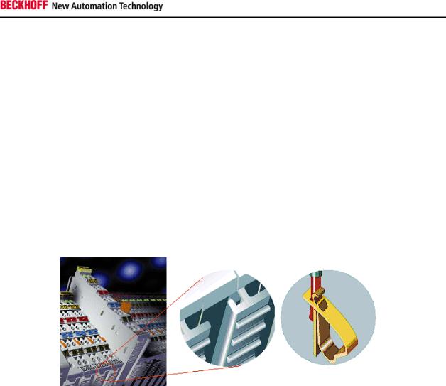
The Beckhoff Bus Terminal system is used for decentralized connection of sensors and actuators to a control system. The Beckhoff Bus Terminal system components are mainly used in industrial automation and building management applications. In its minimum configuration, a bus station consists of a Bus Coupler or a Bus Terminal Controller and Bus Terminals connected to it. The Bus Coupler forms the communication interface to the higher-level controller, and the terminals are the interface to sensors and actuators. The whole bus station is clipped onto a 35 mm DIN mounting rail (EN 50022). The mechanical cross connection of the bus station is established via a slot and key system at the Bus Coupler and the Bus Terminals.
The sensors and actuators are connected with terminals via the screwless Cage Clamp© connection system.
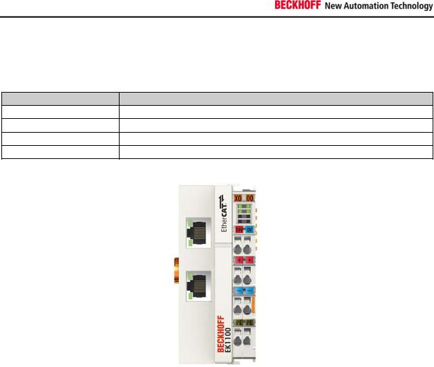
In order to accommodate the wide range of different communication standards encountered in industrial automation, Beckhoff offers Bus Couplers for a number of common bus systems (e.g. EK1100 for EtherCAT).
EL1904 |
7 |
System description
2.1.1 Bus Coupler
Mechanical data
Mechanical data |
Bus Coupler |
Material |
polycarbonate, polyamide (PA6.6). |
Dimensions (W x H x D) |
44 mm x 100 mm x 68 mm |
Installation |
on 35 mm mounting rail (EN50022) with locking |
Attachable by |
double slot and key connection |
Connection technology
Connection technology |
Bus Coupler |
Wiring |
Cage Clamp® spring-loaded system |
Connection cross-section |
0.08 mm2 ... 2.5 mm2, stranded wire, solid wire |
Fieldbus connection |
depending on fieldbus |
Power contacts |
3 spring contacts |
Current load |
10 A |
Rated voltage |
24 VDC |
8 |
EL1904 |

System description
2.1.2 Bus Terminals
Mechanical data
Mechanical data |
Bus Terminal |
Material |
polycarbonate, polyamide (PA6.6). |
Dimensions (W x H x D) |
12 mm x 100 mm x 68 mm or 24 mm x 100 mm x 68 mm |
Installation |
on 35 mm mounting rail (EN50022) with locking |
Attachable by |
double slot and key connection |
Connection technology
Connection technology |
Bus Terminal |
Wiring |
Cage Clamp® spring-loaded system |
Connection cross-section |
0.08 mm2 ... 2.5 mm2, stranded wire, solid wire |
Fieldbus connection |
E-bus |
Power contacts |
up to 3 blade/spring contacts |
Current load |
10 A |
Rated voltage |
depends on Bus Terminal type |
2.1.3 E-bus
The E-bus is the data path within a terminal strip. The E-bus is led through from the Bus Coupler through all the terminals via six contacts on the terminals' side walls.
2.1.4 Power contacts
The operating voltage is passed on to following terminals via three power contacts. Terminal strip can be split into galvanically isolated groups by means of potential feed terminals as required. The power feed terminals play no part in the control of the terminals, and can be inserted at any locations within the terminal strip.
EL1904 |
9 |

System description
2.2 TwinSAFE
2.2.1 The I/O construction kit is extended safely
With the TwinSAFE Terminals, Beckhoff offers the option of simply expanding the proven Bus Terminal system, and to transfer the complete cabling for the safety circuit into the already existing fieldbus cable. Safe signals can be mixed with standard signals without restriction. This saves design effort, installation and material. Maintenance is simplified significantly through faster diagnosis and simple replacement of only a few components.
The new ELx9xx series Bus Terminals only include three basic functionalities: digital inputs EL19xx, digital outputs EL29xx and a logic unit EL6900. For a large number of applications, all sensors and actuators can be wired on these Bus Terminals. The required logical link of the inputs and the outputs is handled by the EL6900. For small to medium-sized configurations, the tasks of a fail-safe PLC can thus be handled within the Bus Terminal system.
2.2.2 Safety concept
TwinSAFE: Safety and I/O technology in one system
Extension of the familiar Beckhoff I/O system with TwinSAFE terminals
Freely selectable mix of safe and standard signals
Logical link of the I/Os in the EL6900 TwinSAFE logic terminal
Safety-relevant networking of machines via bus systems
TwinSAFE protocol (Fail Safe over EtherCAT - FSoE)
Transfer of safety-relevant data via any media (“genuine black channel”)
TwinSAFE communication via fieldbus systems such as EtherCAT, Lightbus, PROFIBUS or Ethernet
IEC 61508:2010 SIL 3 compliant
Configuring instead of wiring: the TwinSAFE configurator
Configuration of the TwinSAFE system via the TwinCAT System Manager
System Manager for editing and displaying all bus parameters
Certified function blocks such as emergency stop, operation mode, etc.
Simple handling
Typical function blocks for machine safety
Any bus connection with the EL6900 TwinSAFE logic terminal
TwinSAFE logic Bus Terminal EL6900
Link unit between TwinSAFE input and output terminals
Configuration of a simple, flexible, cost-effective, decentralized safety controller
No safety requirements for higher-level control system
TwinSAFE enables networks with up to 65535 TwinSAFE devices
TwinSAFE logic terminal can establish up to 128 connections (TwinSAFE connections).
Several TwinSAFE logic terminals are cascadable in a network
Safety functions such as emergency stop, protective door etc. are already included
Suitable for applications up to SIL 3 according to IEC 61508:2010 and DIN EN ISO 13849- 1:2006 (Cat 4, PL e).
10 |
EL1904 |

System description
TwinSAFE digital input (EL1904) and output terminal (EL2904)
All current safety sensors can be connected
Operation with a TwinSAFE logic terminal
EL1904 with 4 fail-safe inputs for sensors (24 VDC) with floating contacts
EL2904 with four safe channels for actuators (24 VDC, 0.5 A per channel)
Conforming to IEC 61508:2010 SIL 3 and DIN EN ISO 13849-1:2006 (Cat 4, PL e) requirements.
2.2.3 EL1904, EL2904 – Bus Terminals with 4 fail-safe inputs or outputs
The EL1904 and EL2904 Bus Terminals enable connection of common safety sensors and actuators. They are operated with the EL6900 TwinSAFE logic terminal. The TwinSAFE logic terminal is the link unit between the TwinSAFE input and output terminals. It enables the configuration of a simple, flexible and cost-effective decentralized safety control system.
Therefore, there are no safety requirements for the higher-level controller! The typical safety functions required for the automation of machines, such as emergency stop, protective door, two-hand etc., are already permanently programmed in the EL6900. The user configures the EL6900 terminal according to the safety requirements of his application.
2.2.4 EL6900 - TwinSAFE logic terminal
The TwinSAFE logic terminal is the link unit between the TwinSAFE input and output terminals. The EL6900 meets the requirements of IEC 61508:2010 SIL 3, EN 954 Cat. 4 and DIN EN ISO 13849-1:2006 (Cat 4, PL e).
2.2.5 The fail-safe principle (Fail Stop)
The basic rule for a safety system such as TwinSAFE is that failure of a part, a system component or the overall system must never lead to a dangerous condition. The safe state is always the switched off and wattless state.
EL1904 |
11 |
Product description
3 Product description
3.1 General description
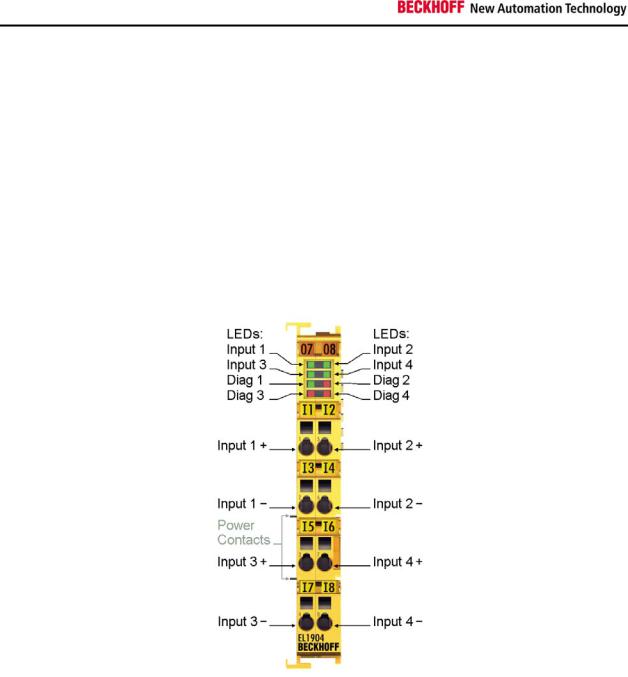
EL1904 - TwinSAFE digital four channel input terminal
The EL1904 is a digital input terminal for encoder with floating contacts for 24 V DC. The Bus Terminal has 4 fail-safe inputs.
With two-channel connection, the EL1904 meets the requirements of IEC 61508:2010 SIL 3, DIN EN ISO 13849-1:2006 (Cat 4, PL e), NRTL, UL508, UL1998 and UL991.
The TwinSAFE terminal has the typical design of an EtherCAT terminal.
12 |
EL1904 |
 Loading...