


CX1000 Embedded PC Hardware documentation
CX1000-0xxx
CX1000-Nxxx
version: 1.1 date: 2006-06-21

Table of contents
Table of contents
CX1000 Hardware Documentation
1. Foreword |
|
Notes on the Manual |
|
Safety instructions |
4 |
Documentation Issue Status |
5 |
2. Product Overview |
6 |
Appropriate Use |
6 |
System Overview |
7 |
Base Modules |
9 |
Technical Data |
9 |
Types |
10 |
Connections |
12 |
Compact flash insert |
14 |
Compact flash card |
14 |
PC 104 bus |
15 |
System interfaces |
17 |
Technical Data |
17 |
Connections CX1000-N001 |
18 |
Connections CX1000-N002 |
20 |
Connections CX1000-N003 |
21 |
Connections CX1000-N005 |
22 |
Power supply |
24 |
Technical data CX1100-0001 |
24 |
Technical data CX1100-0002 / CX1100-0003 |
25 |
Connections CX1100-0001 |
26 |
Connections CX1100-0002 |
27 |
Connections CX1100-0003 |
28 |
LCD display |
29 |
3. |
Transport |
30 |
|
Unpacking, installation and transport |
30 |
4. |
Fitting and wiring |
31 |
|
Mechanical mounting |
31 |
|
Dimensions |
31 |
|
Mechanical Assembly of the base module |
32 |
|
Mechanical Mounting of the Fieldbus modules |
35 |
5. |
Error handling and diagnostics |
37 |
|
CPU base module |
37 |
|
LED CPU base module |
37 |
Embedded PC |
1 |
|

Table of contents
|
Power supplys |
38 |
|
LED CX1100-0001 |
38 |
|
LED CX1100-0002 |
39 |
|
LED CX1100-0003 |
41 |
|
Trouble shooting |
43 |
6. |
Decommissioning |
44 |
|
Removal and disposal |
44 |
7. |
Appendix |
46 |
|
Accessories |
46 |
|
Support |
47 |
|
Certificates |
48 |
2 |
Embedded PC |

Foreword
1. Foreword
Notes on the Manual
This description is only intended for the use of trained specialists in control and automation engineering who are familiar with the applicable national standards. It is essential that the following notes and explanations are followed when installing and commissioning these components.
Liability Conditions
The responsible staff must ensure that the application or use of the products described satisfy all the requirements for safety, including all the relevant laws, regulations, guidelines and standards.
The documentation has been prepared with care. The products described are, however, constantly under development. For that reason the documentation is not in every case checked for consistency with performance data, standards or other characteristics. None of the statements of this manual represents a guarantee (Garantie) in the meaning of § 443 BGB of the German Civil Code or a statement about the contractually expected fitness for a particular purpose in the meaning of § 434 par. 1 sentence 1 BGB. In the event that it contains technical or editorial errors, we retain the right to make alterations at any time and without warning. No claims for the modification of products that have already been supplied may be made on the basis of the data, diagrams and descriptions in this documentation.
© This manual is copyrighted. Any reproduction or third party use of this publication, whether in whole or in part, without the written permission of Beckhoff Automation GmbH, is forbidden.
Associated publication
For commissioning the use of the appropriate hardware documentation is recommended apart from this documentation.
Embedded PC |
3 |
Foreword
Safety Instructions
Safety Rules
The responsible staff must ensure that the application or use of the products described satisfy all the requirements for safety, including all the relevant laws, regulations, guidelines and standards.
State at Delivery
All the components are supplied in particular hardware and software configurations appropriate for the application. Modifications to hardware or software configurations other than those described in the documentation are not permitted, and nullify the liability of Beckhoff Automation GmbH.
Personnel Qualification
This description is only intended for the use of trained specialists in control and automation engineering who are familiar with the applicable national standards.
Description of safety symbols
The following safety symbols are used in this operating manual. They are intended to alert the reader to the associated safety instructions.
Danger
This symbol is intended to highlight risks for the life or health of personnel.
Warning
This symbol is intended to highlight risks for equipment, materials or the environment.
Note
This symbol indicates information that contributes to better understanding.
4 |
Embedded PC |

Foreword
Documentation Issue Status
Version |
Changes |
1.1 |
comments on hardware watchdog added |
|
|
1.0 |
updated version |
|
|
0.1 |
preliminarily version |
Embedded PC |
5 |

Product Overview
2. Product Overview
Appropriate Use
The CX1000 device series is a modular control system that can be mounted on top hat rails. Its components are plugged together and installed in the control cabinet or junction box, depending on the required function.
6 |
Embedded PC |
Product Overview
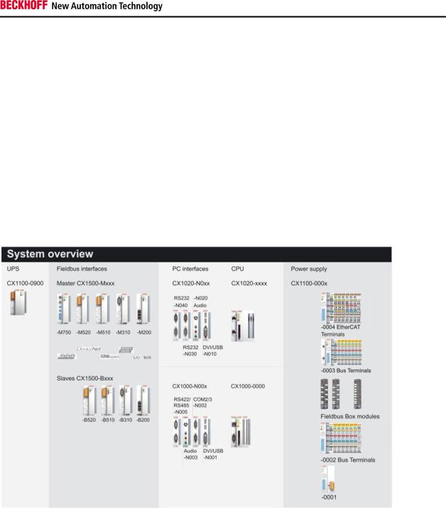
System Overview
The System
The CX1000 system covers the whole range of Beckhoff control technology both in terms of price and performance: The new product range is designed for tasks requiring the characteristics and computing capacity of Industrial PCs, but whose budget does not stretch to full-blown Industrial PCs.
The system only uses those components that are actually required. For example, a CX1000 can be operated in „headless“mode, i.e. without display or keyboard; in this case, the associated interface is not required. Whilst the resulting control system has no visualisation, it does have communications capability via the built-in Ethernet and RS 232 interfaces.
If local visualisation is required, this can be implemented via a DVI (digital video interface), to which all Beckhoff Control Panels and all commercially available monitors with DVI-input can be connected. The touch screen signal is read via one of the two available USB interfaces.
The components
The modules of the CX1000 series system are connected with each other via the standardised PC104 bus (16 bit). The individual system components are modules that can be arranged in series. The basic unit consists of a CPU module(CX1000-0000) and a power supply module(CX1100-000x). Further system interfaces for serial communication(2x RS 232, and RS422, RS485) as well as audio signals are available separately.
CPU base module
The CPU module is available in several variants. These relate to:
–Internal memory configuration: there are two options – either 16 MB Flash/32 MB RAM or 64 MB Flash / 128 MB RAM. The latter is required if the system is to be equipped with Windows XP Embedded.
–System interface configuration: as an option, a DVI and two USB Interfaces can be added to the combination of Ethernet and RS 232 that is always present.
–Operating system: There is a choice between Microsoft Windows CE.NET and Microsoft Windows XP Embedded.
–Pre-installed TwinCAT software: CX1000 can be preinstalled without a TwinCAT system, with TwinCAT CE PLC or with TwinCAT CE NC PTP, or with the associated full version of the individual TwinCAT levels for PLC and Motion Control.
Embedded PC |
7 |

Product Overview
System interfaces
Further system interfaces for serial communication(2x RS 232, and RS422, RS485) as well as audio signals are available separately.
Fieldbus interfaces
The range of optional modules for theCX1000 is complemented by fieldbus connectionsfor Profibus, CANopen, DeviceNet,SERCOS interface and Lightbus, both asmaster and slave versions.
The following fieldbus interfaces are available:
Beckhoff Lightbus (master and slave), Profibus DP (master and slave), CANopen (master and slave), DeviceNet (master and slave) und SERCOS Interface (only master).
The use of fieldbus master modules in a CX1000 system enables the utilisation of all Beckhoff fieldbus components (e. g. Bus Coupler, Bus Terminal Controller, drive technology) as distributed control components for the assembly of complex systems
The use of fieldbus slave modules enables the utilisation of a CX1000 system as subordinate distributed control for the configuration of complex or modular systems.
The Software
In combination with the TwinCAT automation software, the CX1000 Industrial PC becomes a powerful IEC 61131-3 PLC with up to four user tasks. Additionally, MotionControl tasks can also be executed. Depending on the required cycle time, several servo axes can be controlled. Even special functions such as flying saw, electronic gearbox and cam plate can be realised.
The CX1000 system can be programmed in two ways, depending on the operating system used:
Remote programming via Ethernet
This option is used if the basic unit is equipped with Windows CE.NET. In this case, the system is programmed via a laptop or a desktop PC, which is connected to the CX1000 via Ethernet (network or crossover cable). The programs are developed on the laptop with a standard TwinCAT software licence and then loaded into the target device.
Visualisation
The Beckhoff OPC server is available for interfacing with SCADA software on both operating system variants Windows CE.NET or Windows XP Embedded. In other words, the CX1000 also offers unproblematic visualisation and simultaneous control in realtime on a single system. Beckhoff control devices
8 |
Embedded PC |
Product Overview
Base Modules
Technical Data
The CX1000 CPU module is the basic module of the CX system. It comprises the CPU and the internal flash memory in two implementation levels and offers the option to operate an additional memory medium in Compact Flash type II format. Ethernet and an RS 232 interface are also part of the basic configuration. All other CX family components can be connected via the PC104 interface that is available on both sides. The CPU module requires a CX1100 type power supply module.
Technical data |
CX1000-0000 |
Processor |
compatible with Pentium MMX, clock frequency 266 MHz |
|
|
Flash memory |
64 MByte Compact Flash card |
|
|
Internal main memory |
32 MByte RAM (expandable to 128 MByte) |
Interfaces |
1 x RJ45 (Ethernet) and 1 x 9-pinD-Sub (RS 232) |
|
|
Diagnostics LED |
1 x Power, 1 x Link, 1x 100 MBit , 1 x LAN Aktivität, |
|
1 x Flash access |
Expansion slot |
1 x Compact Flash type II insert with ejector |
|
|
Clock |
battery-powered internal clock for time and date |
|
|
Operating system |
Microsoft Windows CE.NET or Microsoft |
|
Windows XP Embedded |
Control software |
TwinCAT PLC Runtime or TwinCAT NC PTP Runtime |
|
|
System bus |
16 Bit ISA (PC104 standard) |
Power supply |
via system bus (through CX1100 power supply module) |
|
|
Dimensions |
57 mm x 100 mm x 91 mm |
Weight approx. |
355 g ( with DVI/USB 435 g) |
|
|
The passive cooling module CX1000-COOL is included in the scope of supply.
Note
The Watchdog function is only supported by Beckhoff in combination of TwinCAT with WINDOWS NT based systems. For other operating systems without TwinCAT it is not possible to give a general solution. The user must find a solution to the implementation of watchdog access on his own. As the only support Beckhoff can provide
the processor hardware description
the CX-architecture description (CX1100-000x power supply manual)
The documents can be found in the Download area of our webserver (www.beckhoff.com)..
Embedded PC |
9 |
Product Overview
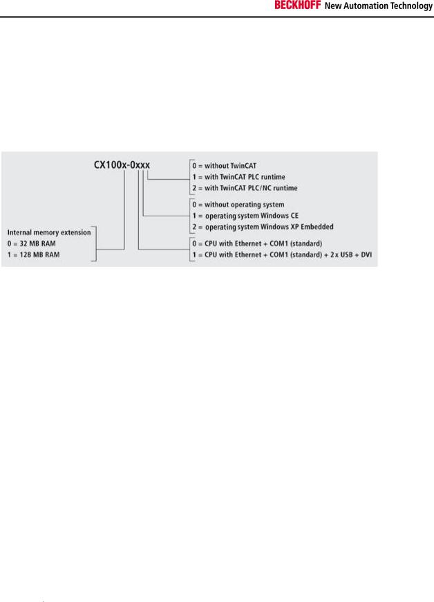
Types
The CPU module can be equipped with different hardware and software options: the internal memory is expandable to 32 MB Flash/128 MB RAM; the operating systems can be Windows CE.NET or Windows XP Embedded. The TwinCAT automation software transforms a CX1000 system into powerful PLC and Motion Control system that can be operated with or without visualisation. Further system interfaces (pre-installed in the factory) or fieldbus connections can be added to the basic CPU module.
Since not all combinations are sensible, the following table contains a breakdown of the permissible combinations.
The CX 1000 modules are available in the following types:
|
|
|
|
|
|
|
|
TwinCAT |
|
|
TwinCAT NC |
|
|
|
|
|
|
|
|
|
|
|
|
||
|
16/32 |
64/128 |
DVI / |
Windows |
Windows |
without |
|
PLC |
|
|
PTP |
|
Modules |
MB |
MB |
USB |
CE.NET |
XPE |
TwinCAT |
|
Runtime |
|
|
Runtime |
|
|
|
|
|
|
|
|
|
|
|
|
|
|
CX1000- |
* |
|
|
* |
|
* |
|
|
|
|
|
|
0010 |
|
|
|
|
|
|
|
|
|
|
|
|
CX1000- |
* |
|
|
* |
|
|
* |
|
|
|
|
|
0011 |
|
|
|
|
|
|
|
|
|
|
|
|
CX1000- |
* |
|
|
* |
|
|
|
|
|
* |
|
|
0012 |
|
|
|
|
|
|
|
|
|
|
|
|
CX1000- |
* |
|
* |
* |
|
* |
|
|
|
|
|
|
0110 |
|
|
|
|
|
|
|
|
|
|
|
|
CX1000- |
* |
|
* |
* |
|
|
* |
|
|
|
|
|
0111 |
|
|
|
|
|
|
|
|
|
|
|
|
CX1000- |
* |
|
* |
* |
|
|
|
|
|
* |
|
|
0112 |
|
|
|
|
|
|
|
|
|
|
|
|
CX1001- |
* |
|
|
|
|
|
|
|
|
|
|
|
0000 |
|
|
|
|
|
|
|
|
|
|
|
|
CX1001- |
|
* |
|
* |
|
* |
|
|
|
|
|
|
0010 |
|
|
|
|
|
|
|
|
|
|
|
|
CX1001- |
|
* |
|
* |
|
|
* |
|
|
|
|
|
0011 |
|
|
|
|
|
|
|
|
|
|
|
|
CX1001- |
|
* |
|
* |
|
|
|
|
|
* |
|
|
0012 |
|
|
|
|
|
|
|
|
|
|
|
|
CX1001- |
|
* |
|
|
* |
* |
|
|
|
|
|
|
0020 |
|
|
|
|
|
|
|
|
|
|
|
|
CX1001- |
|
* |
|
|
* |
|
* |
|
|
|
|
|
0021 |
|
|
|
|
|
|
|
|
|
|
|
|
CX1001- |
|
* |
|
|
* |
|
|
|
|
* |
|
|
0022 |
|
|
|
|
|
|
|
|
|
|
|
|
CX1001- |
|
* |
* |
* |
|
* |
|
|
|
|
|
|
0110 |
|
|
|
|
|
|
|
|
|
|
|
|
CX1001- |
|
* |
* |
* |
|
|
* |
|
|
|
|
|
0111 |
|
|
|
|
|
|
|
|
|
|
|
|
10 Embedded PC

|
|
|
|
|
|
|
|
|
Product Overview |
|
|
|
|
|
|
|
|
|
|
|
|
|
|
|
|
|
|
|
|
|
|
|
|
CX1001- |
|
* |
* |
* |
|
|
|
* |
|
|
0112 |
|
|
|
|
|
|
|
|
|
|
CX1001- |
|
* |
* |
|
* |
* |
|
|
|
|
0120 |
|
|
|
|
|
|
|
|
|
|
CX1001- |
|
* |
* |
|
* |
|
* |
|
|
|
0121 |
|
|
|
|
|
|
|
|
|
|
CX1001- |
|
* |
* |
|
* |
|
|
* |
|
|
0122 |
|
|
|
|
|
|
|
|
|
CX1000 systems with Windows XP Embedded require a Compact Flash card with a minimum capacity of 128 MB.
Note:
A list of the different software images can be found in the CX1000 Software Documentation.
Embedded PC |
11 |
Product Overview
Connections
The basic CPU module is available with different hardware and software options. It is supplied from the power supply unit, so that only the connections are described here.
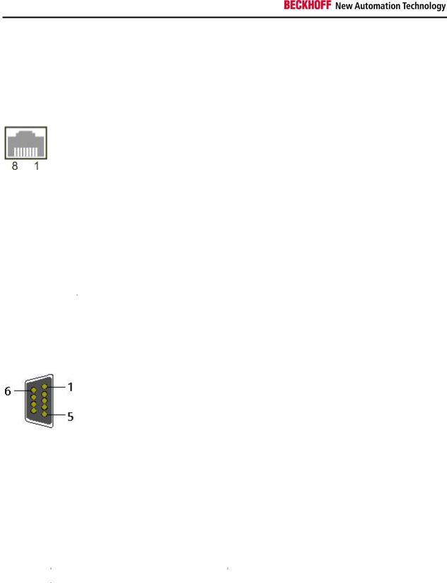
Basic CPU module with Ethernet RJ 45 and COM1 (RS232) interface:
RJ 45 interface (socket):
Assignment of the RJ45 interface:
PIN |
Signal |
|
Description |
1 |
TD + |
|
Transmit + |
|
|
|
|
2 |
TD - |
|
Transmit - |
3 |
RD + |
|
Receive + |
|
|
|
|
4 |
connected |
|
not used |
|
|
|
|
5 |
|
|
|
|
|
|
|
6 |
RD - |
|
Receive - |
|
|
|
|
7 |
connected |
|
not used |
|
|
|
|
8 |
|
|
|
|
|
|
|
TD & RD are exchanged at the hubs or between two PCs.
COM1 interface (connector):
Assignment of the COM1 interface:
|
PIN |
|
|
Signal |
|
|
Type |
|
|
Description |
|
|
|
|
|
|
|
|
|
||||
|
|
|
|
|
|
|
|
|
|
|
|
1 |
|
|
DCD |
|
Signal in |
|
Data Carrier Detect |
||||
|
|
|
|
|
|
|
|
||||
2 |
|
|
RxD |
|
Signal in |
|
Receive Data |
||||
|
|
|
|
|
|
|
|
||||
3 |
|
|
TxD |
|
Signal out |
|
Transmit Data |
||||
4 |
|
|
DTR |
|
Signal out |
|
Data Terminal Ready |
||||
|
|
|
|
|
|
|
|
||||
5 |
|
|
GND |
|
Ground |
|
Ground |
||||
|
|
|
|
|
|
|
|
||||
6 |
|
|
DSR |
|
Signal in |
|
Data Set Ready |
||||
7 |
|
|
RTS |
|
Signal out |
|
Request to Send |
||||
|
|
|
|
|
|
|
|
||||
8 |
|
|
CTS |
|
Signal in |
|
Clear to Send |
||||
|
|
|
|
|
|
|
|
||||
9 |
|
|
RI |
|
Signal in |
|
Ring Indicator |
||||
|
|
|
|
|
|
|
|
|
|
|
|
12 |
Embedded PC |

Product Overview
Basic CPU module with DVI/USB interface:
In addition to the Ethernet and COM interface, this basic module features a DVI-I and two USB interfaces. The pin assignment of the basic CPU module with two USB and a DVI-I interface is explained under the associated system interface CX1000-N001.
Applicable to all basic CPU modules:
LED
The green power LED (PWR) is on if the basic CPU module is connected correctly to a live power supply unit.
Compact Flash slot
Further information can be found under Compact Flash slot.
PC 104 Bus
The PC 104 bus is a standardised bus with 104 ISA signals for compact embedded systems.
Embedded PC |
13 |
 Loading...