


© 1999 aprilia s.p.a. - Noale (VE)
First edition: may 1999
Reprint: november 1999, march 2001
Produced and printed by: 
 editing division
Soave (VERONA) - Italy Tel. +39 - 045 76 11 911 Fax +39 - 045 76 12 241 E-mail: customer@stp.it www.stp.it
On behalf of: aprilia s.p.a.
via G. Galilei, 1 - 30033 Noale (VE) - Italy Tel. +39 - 041 58 29 111
Fax +39 - 041 44 10 54 www.aprilia.com
3!&%49 7!2.).'3
The following precautionary warnings are used throughout this manual in order to convey the following messages:
Safety warning. When you find this asymbol on the vehicle or in the manual, be careful to the potential risk of personal injury. Non-compliance with the indications given in the messages preceded by this symbol may result in grave risks for your and other people’s safety and for the vehicle!
aWARNING
Indicates a potential hazard which may result in serious injury or even death.
aCAUTION
Indicates a potential hazard which may result in minor personal injury or damage to the vehicle.
NOTE The word “NOTE” in this manual precedes important information or instructions.
 4%#(.)#!,
The operations preceded by this
symbol must be repeated also on the opposite side of the vehicle.
If not expressly indicated otherwise, for the reassembly of the units repeat the disassembly operations in reverse order.
The terms “right” and “left” are referred to the rider seated on the vehicle in the normal riding position.
. Any mention to the use of the vehicle with passenger is to be intended as referred only to the countries where this is allowed.
In the text and figures the symbols 31 2 preceded by the symbol of the model (.•+) refer exclusively to the model indicated.
7!2.).'3 02%#!54)/.3 '%.%2!, !$6)#%
Before starting the engine, carefully read this manual and in particular the section “SAFE DRIVE”.
Your and other people’s safety depends not only on your quickness of reflexes and on your agility, but also on what you know about the vehicle, on its efficiency and on your knowledge of the basic information for “SAFE DRIVE”. Therefore, get a thorough knowledge of the vehicle, in such a way as to be able to drive in the traffic safely.
2use and maintenance SR 50 - SR 125 - SR 150
NOTE This manual must be considered as an integral part of the vehicle and must always accompany it, even in case of resale.
aprilia has carried out this manual with the maximum attention, in order to supply the user with correct and updated information. However, since aprilia constantly improves the design of its products, there may be slight discrepancies between the characteristics of your vehicle and those described in this manual.
For any clarification concerning the information contained in this manual, do not hesitate to contact your aprilia Official Dealer.
For control and repair operations not expressly described in this publication, for the purchase of aprilia genuine spare parts, accessories and other products, as well as for specific advice, contact exclusively aprilia Official Dealers and Service Centers, which guarantee prompt and accurate assistance.
Thank you for choosing aprilia. We wish you a nice ride.
All rights as to electronic storage, reproduction and total or partial adaptation, with any means, are reserved for all Countries.
NOTE In some countries the antipollution and noise regulations in force require periodical inspections.
The user of the vehicle in these countries must:
–contact an aprilia Official Dealer to have the non-homologated components replaced with others homologated for use in the country in question;
–carry out the required periodical inspections.
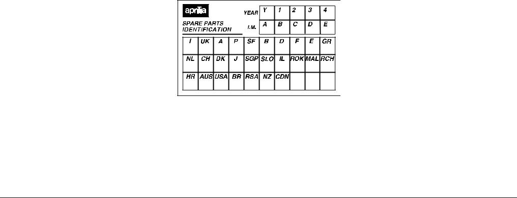
NOTE Soon after purchasing the vehicle, write down the identification data indicated on the SPARE PARTS IDENTIFICATION LABEL in the table here below. The label is stuck on the right beam of the frame; to be able to read it, remove the right inspection cover, see p. 55 (REMOVING THE RIGHT AND LEFT INSPECTION COVERS).
These data indicate:
–YEAR = year of manufacture (Y, 1, 2, ...);
–I.M. = modification code (A, B, C, ...);
–COUNTRY CODES = homologation country (I, UK, A, ...).
and are to be supplied to the aprilia Official Dealer as reference data for the purchase of spare parts or specific accessories of the model you have acquired.
In this manual the various versions are indicated by the following symbols:
x 50 cm# model z 125 cm# model
{ 150 cm# model
eautomatic light switching version (Automatic Switch-on Device)
m optional
q liquid-cooled version t drum brake version o catalytic version
VERSION: |
|
I Italy |
S Singapore |
U United Kingdom |
s Slovenia |
a Austria |
i Israel |
p Portugal |
¬ South Korea |
F Finland |
M Malaysia |
B Belgium |
c Chile |
d Germany |
H Croatia |
f France |
A Australia |
E Spain |
u United States |
|
of America |
G Greece |
Ä Brazil |
O Holland |
R South Africa |
Y Switzerland |
n New Zealand |
D Denmark |
C Canada |
J Japan |
|
use and maintenance SR 50 - SR 125 - SR 150 3

4!",% /& #/.4%.43 |
|
SAFE DRIVE ............................................................... |
5 |
BASIC BASIC SAFETY RULES ............................... |
6 |
CLOTHING ............................................................... |
9 |
ACCESSORIES ...................................................... |
10 |
LOAD ...................................................................... |
10 |
ARRANGEMENT |
|
OF TmHE MAIN ELEMENTS .............................. |
12 |
ARRANGEMENT |
|
OF THE MAIN ELEMENTS •+......................... |
14 |
ARRANGEMENT OF THE CONTROLS / |
|
INSTRUMENTS AND INDICATORS......................... |
16 |
INSTRUMENT AND INDICATOR TABLE............... |
17 |
MAIN INDEPENDENT CONTROLS .................... |
18 |
CONTROLS ON THE LEFT SIDE |
|
OF THE HANDLEBAR............................................ |
18 |
CONTROLS ON THE RIGHT SIDE |
|
OF THE HANDLEBAR............................................ |
19 |
MAIN INDEPENDENT CONTROLS •+............ |
20 |
CONTROLS ON THE LEFT SIDE |
|
OF THE HANDLEBAR............................................ |
20 |
CONTROLS ON THE RIGHT SIDE |
|
OF THE HANDLEBAR............................................ |
21 |
IGNITION SWITCH................................................. |
22 |
STEERING LOCK................................................... |
22 |
AUXILIARY EQUIPMENT ......................................... |
23 |
UNLOCKING / LOCKING THE SADDLE................ |
23 |
CRASH HELMET / GLOVE COMPARTMENT ....... |
23 |
ANTI-THEFT HOOK ............................................... |
23 |
BATTERY / TOOL KIT COMPARTMENT............... |
24 |
BAG HOOK............................................................. |
24 |
REAR MUDGUARD EXTENSION .......................... |
24 |
•+DIRECTION |
|
INDICATOR EXTENSIONS .................................... |
24 |
MAIN COMPONENTS............................................... |
25 |
FUEL....................................................................... |
25 |
LUBRICANTS ......................................................... |
26 |
BRAKE FLUID - recommendations......................... |
27 |
DISC BRAKES........................................................ |
28 |
REAR DRUM BRAKE ............................................. |
29 |
.COOLANT 1................................................ |
30 |
TYRES .................................................................... |
32 |
.AUTOMATIC |
|
LIGHT SWITCHING VERSION _....................... |
33 |
•+AUTOMATIC |
|
LIGHT SWITCHING VERSION _....................... |
33 |
CATALYTIC SILENCER 2.................................. |
34 |
EXHAUST SILENCER ............................................ |
34 |
INSTRUCTIONS FOR USE ....................................... |
35 |
PRELIMINARY CHECKING OPERATIONS ........... |
35 |
STARTING.............................................................. |
36 |
DEPARTURE AND DRIVE ..................................... |
38 |
.RUNNING-IN ................................................... |
40 |
•+RUNNING-IN ............................................ |
40 |
STOPPING ............................................................. |
41 |
PARKING................................................................ |
41 |
POSITIONING THE VEHICLE |
|
ON THE STAND ..................................................... |
42 |
SUGGESTIONS TO PREVENT THEFT ................. |
42 |
MAINTENANCE ........................................................ |
43 |
REGULAR SERVICE |
|
INTERVALS CHART ................................... |
44-45 |
REGULAR SERVICE |
|
INTERVALS CHART •+............................ |
46-47 |
IDENTIFICATION DATA......................................... |
48 |
.AIR CLEANER ................................................. |
49 |
•+AIR CLEANER .......................................... |
50 |
CHECKING THE BRAKE PAD WEAR.................... |
51 |
CHECKING THE SHOE WEAR.............................. |
51 |
CHECKING THE STEERING.................................. |
52 |
CHECKING THE ENGINE FULCRUM AXIS .......... |
52 |
REMOVING |
|
THE COVER SUPPORT ELEMENT....................... |
53 |
REMOVING THE FRONT COVER ......................... |
53 |
REMOVING |
|
THE LOWER HANDLEBAR COVER...................... |
54 |
PARTIAL REMOVAL |
|
OF THE UPPER HANDLEBAR COVER................. |
54 |
REMOVING THE RIGHT |
|
AND LEFT INSPECTION COVERS........................ |
55 |
.INSTALLING |
|
THE REAR MUDGUARD EXTENSION.................. |
56 |
•+REMOVING |
|
THE NUMBER PLATE SUPPORT.......................... |
56 |
•+INSTALLING |
|
THE REAR MUDGUARD EXTENSION.................. |
57 |
•+REMOVING |
|
THE WHOLE DIRECTION INDICATOR ................. |
58 |
•+INSTALLING |
|
THE DIRECTION INDICATOR EXTENSIONS ....... |
58 |
.REMOVING THE LOWER SHIELD COVER ...59 |
|
REMOVING THE FRONT INNER SHIELD............ |
|
60 |
REMOVING THE REAR-VIEW MIRRORS ............ |
|
61 |
CHECKING THE STAND....................................... |
|
61 |
CHECKING THE SWITCHES ................................ |
|
61 |
.IDLING ADJUSTMENT ................................... |
|
62 |
•+IDLING ADJUSTMENT............................ |
|
63 |
ADJUSTING THE ACCELERATOR CONTROL |
.... |
63 |
SPARK PLUG ........................................................ |
|
64 |
BATTERY............................................................... |
|
65 |
LONG INACTIVITY OF THE BATTERY ................ |
|
65 |
CHECKING AND CLEANING THE TERMINALS .. |
66 |
|
REMOVING THE BATTERY.................................. |
|
66 |
INSTALLING THE BATTERY ................................ |
|
67 |
.CHECKING THE ELECTROLYTE LEVEL...... |
|
67 |
.RECHARGING THE BATTERY ...................... |
|
68 |
•+RECHARGING THE BATTERY............... |
|
68 |
CHANGING THE FUSES....................................... |
|
69 |
ADJUSTING |
|
|
THE VERTICAL HEADLIGHT BEAM..................... |
|
70 |
BULBS ................................................................... |
|
70 |
.CHANGING THE HEADLIGHT BULBS .......... |
|
71 |
.CHANGING THE HEADLIGHT BULBS |
|
|
C%K-_............................................. |
|
71 |
•+CHANGING THE HEADLIGHT BULBS ... |
72 |
|
CHANGING THE FRONT |
|
|
DIRECTION INDICATOR BULBS.......................... |
|
73 |
CHANGING THE REAR |
|
|
DIRECTION INDICATOR BULBS.......................... |
|
73 |
CHANGING THE DASHBOARD BULBS ............... |
|
74 |
CHANGING THE REAR LIGHT BULB................... |
|
75 |
CHANGING THE NUMBER PLATE BULB ............ |
|
75 |
TRANSPORT............................................................ |
|
76 |
DRAINING THE FUEL TANK................................. |
|
76 |
CLEANING ............................................................... |
|
77 |
LONG PERIODS OF INACTIVITY ......................... |
|
78 |
TECHNICAL DATA .................................................. |
|
79 |
.LUBRICANT CHART ...................................... |
|
84 |
•+LUBRICANT CHART ............................... |
|
85 |
Importers ........................................................... |
86-87 |
|
WIRING DIAGRAM - SR 50................................... |
|
88 |
WIRING DIAGRAM - SR 50 C%K_....... |
|
90 |
WIRING DIAGRAM - SR 50 -............................ |
|
92 |
WIRING DIAGRAM - SR 125 - SR 150.................. |
|
94 |
WIRING DIAGRAM - SR 125 - SR 150 J........... |
|
96 |
4use and maintenance SR 50 - SR 125 - SR 150
safe drive
"!3)# "!3)# 3!&%49 25,%3 |
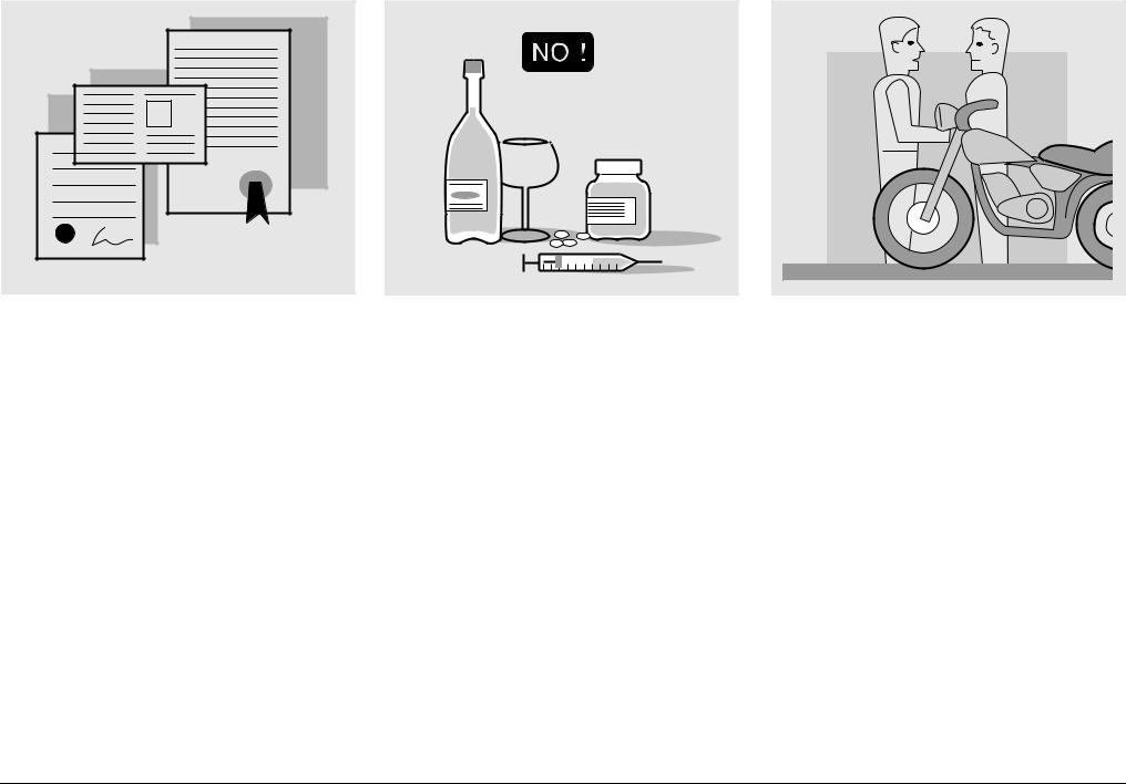
To drive the vehicle it is necessary to be in possession of all the requirements prescribed by law (driving licence, minimum age, psychophysical ability, insurance, state taxes, vehicle registration, number plate, etc.).
Gradually get to know the vehicle by driving it first in areas with low traffic and/or private areas.
The use of medicins, alcohol and drugs or psychotropic substances notably increases the risk of accidents.
Be sure that you are in good psychophysical conditions and fit for driving and pay particular attention to physical weariness and drowsiness.
Most road accidents are caused by the driver’s lack of experience.
NEVER lend the vehicle to beginners and, in any case, make sure that the driver has all the requirements for driving.
6use and maintenance SR 50 - SR 125 - SR 150
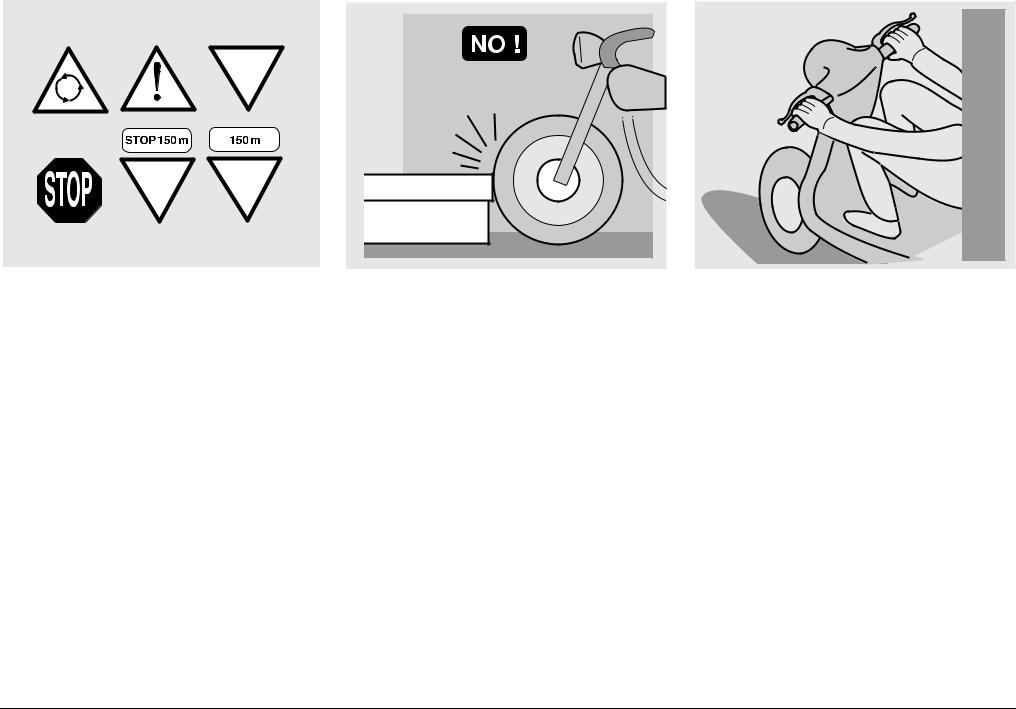
Rigorously observe all road signs and national and local road regulations.
Avoid abrupt movements that can be dangerous for yourself and other people (for example: rearing up on the back wheel, speeding, etc.), and give due consideration to the road surface, visibility and other driving conditions.
Avoid obstacles that could damage the vehicle or make you lose control.
Avoid riding in the slipstream created by preceding vehicles in order to increase your speed.
Always keep both hands on the handlebars and both feet on the footboard (or on the footrests), in the correct driving posture.
Avoid standing up or stretching your limbs while driving.
use and maintenance SR 50 - SR 125 - SR 150 |
7 |
OIL |
COOLER |
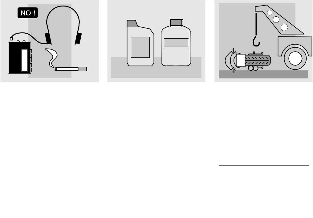
The driver should pay attention and avoid distractions caused by people, things and movements (never smoke, eat, drink, read, etc.) while driving.
Use only the vehicle’s specific fuels and lubricants indicated in the "LUBRICANT CHART"; check all oil, fuel and coolant levels regularly.
If the vehicle has been involved in an accident, make sure that no damage has occurred to the control levers, pipes, wires, braking system and vital parts.
If necessary, have the vehicle inspected by an aprilia Official Dealer, who should carefully check the frame, handlebars, suspensions, safety parts and all the devices that you cannot check by yourself.
Always remember to report any malfunction to the technicians to help them in their work.
Never use the vehicle when the amount of damage it has suffered endangers your safety.
Never change the position, inclination or colour of: number plate, direction indicators, lights and horns.
Any modification of the vehicle will result in the invalidity of the guarantee.
For only vehicles up to 50 cm3 included
Any modification of the engine or of other members which is aimed at increasing the speed or the power of the vehicle is prohibited by the law; in fact, any modification resulting in an increase of the maximum speed or of the engine displacement would change the scooter into a motorcycle,
8use and maintenance SR 50 - SR 125 - SR 150
12 |
A |
5 |
34 |
which implies the following obligations for the owner:
–new homologation;
–new registration;
–appropriate driving license.
Further, said modifications cause the loss of the insurance cover, since insurance policies expressly prohibit to make technical changes aimed at increasing the vehicle performance levels.
For the reasons stated above, the failure to comply with the tampering prohibition is punished by law with appropriate sanctions (including the confiscation of the vehicle), which, according to the case, can be combined with the sanctions provided for not using the crash helmet and/or the number plate, for the violation of fiscal obligations (ownership tax) and with penal sanctions provided for using the vehicle without driving license.
ONLY ORIGINALS
For only vehicles over 50 cm3
Any modification of the vehicle and/or the removal of original components can compromise vehicle performance levels and safety or even make it illegal.
We recommend respecting all regulations and national and local provisions regarding the equipment of the vehicle.
In particular, avoid all modifications that increase the vehicle’s performance levels or alter its original characteristics.
Never race with other vehicles.
Avoid off-road driving.
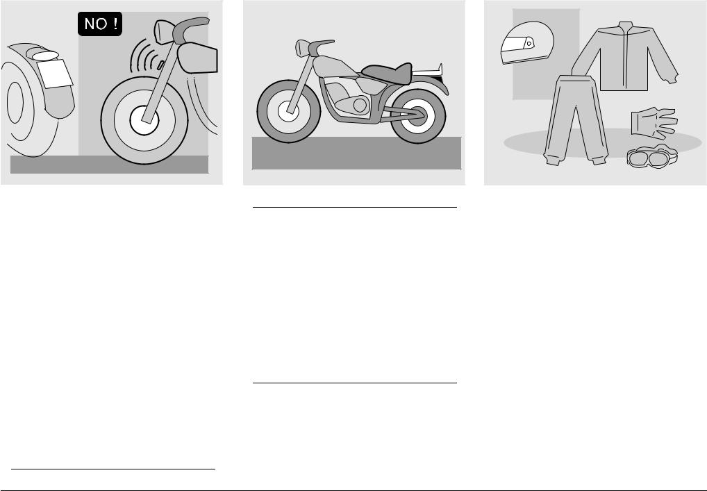
#,/4().' |
Before starting, always wear a correctly fastened crash helmet. Make sure that it is homologated, in good shape, of the right size and that the visor is clean.
Wear protective clothing, preferably in light and/or reflecting colours.
In this way you will make yourself more visible to the other drivers, thus notably reducing the risk of being knocked down, and you will be more protected in case of fall.
This clothing should be very tight-fitting and fastened at the wrists and ankles. Strings, belts and ties should not be hanging loose; prevent these and other objects from interfering with driving by getting entangled with moving parts or driving mechanisms.
use and maintenance SR 50 - SR 125 - SR 150 |
9 |
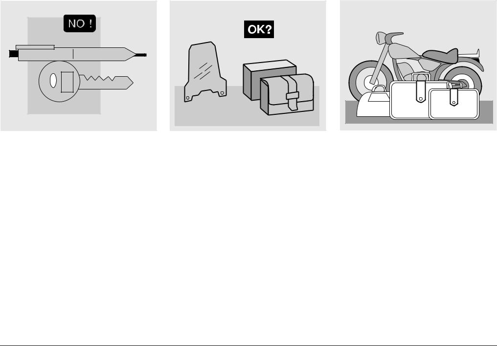
Do not keep objects that can be dangerous in case of fall, for example pointed objects like keys, pens, glass vials etc. in your pockets (the same recommendations also apply to passengers).
!##%33/2)%3
The owner of the vehicle is responsible for the choice, installation and use of any accessory.
Avoid installing accessories that cover horns or lights or that could impair their functions, limit the suspension stroke and the steering angle, hamper the operation of the controls and reduce the distance from the ground and the angle of inclination in turns.
Avoid using accessories that hamper access to the controls, since this can prolong reaction times during an emergency.
Big fairings and windshields installed on the vehicle may produce aerodynamic forces that affect the stability of the vehicle, especially when riding at high speed.
Make sure that the equipment is well fastened to the vehicle and not dangerous during driving. Do not install electrical devices and do not modify those already existing to avoid electrical overloads, because the vehicle could suddenly stop or there could be a dangerous current shortage in the horn and in the lights.
aprilia recommends the use of “aprilia genuine accessories”.
,/!$
Be careful and moderate when loading your luggage. Keep any luggage loaded as close as possible to the center of gravity of the vehicle and distribute the load uniformly on both sides, in order to reduce imbalance to the minimum. Furthermore, make sure that the load is firmly secured to the vehicle, especially during long trips.
10 use and maintenance SR 50 - SR 125 - SR 150
KG! |
Avoid hanging bulky, heavy and/or dangerous objects on the handlebars, mudguards and forks: the vehicle might respond more slowly in turns and its manoeuvrability could be unavoidably impaired.
Do not place bags that are too bulky on the vehicle sides, because they could hit people or obstacles, making you lose control of the vehicle.
Do not carry any bag if it is not tightly secured to the vehicle.
Do not carry bags which protrude too much from the luggage-rack or which cover the lights, horn or indicators.
Do not carry animals or children on the glove compartment or on the luggagerack.
Do not exceed the maximum load allowed for each side-bag.
When the vehicle is overloaded, its stability and its manoeuvrability can be compromised.
use and maintenance SR 50 - SR 125 - SR 150 11
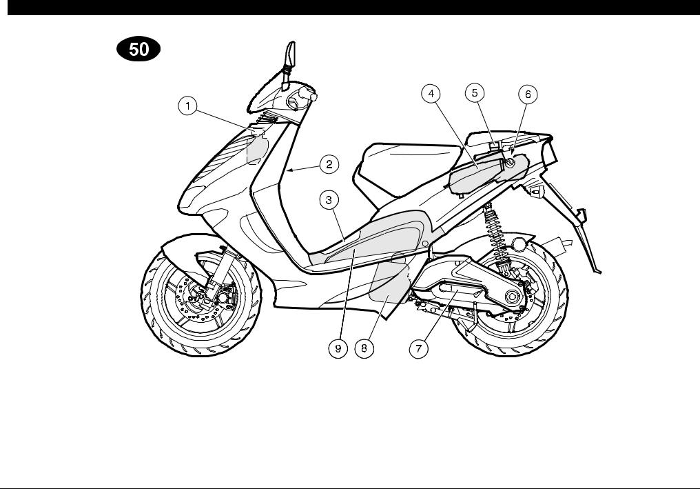
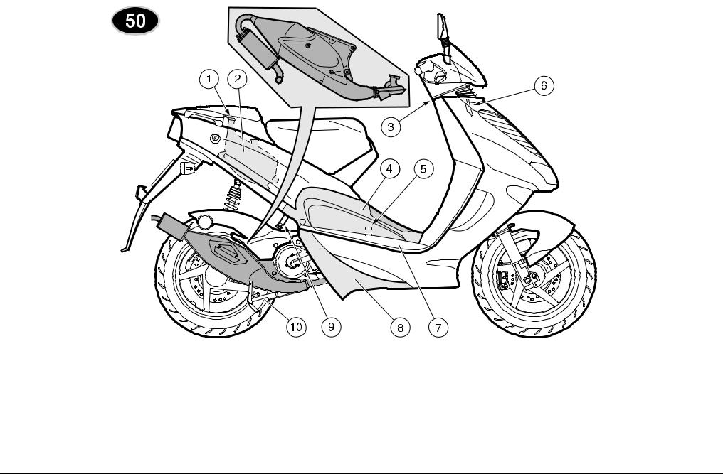
 !22!.'%-%.4 /& 4(% -!). %,%-%.43 .
|
|
|
|
|
+%9 |
|
|
||
1) |
Coolant expansion tank plug 1 |
6) |
Saddle lock |
|
2) |
Bag hook |
7) |
Kick starter |
|
3) |
Battery/tool kit compartment cover |
8) |
Air cleaner |
|
4) |
Fuel tank |
9) |
Left inspection cover |
|
5) |
Fuel tank plug |
|
|
|
12 use and maintenance SR 50 - SR 125 - SR 150
|
|
|
|
|
|
|
|
|
|
|
|
|
|
|
|
|
|
|
|
|
|
|
|
|
|
|
|
|
|
|
|
|
|
|
|
|
|
|
|
|
|
|
|
|
|
|
|
|
|
|
|
|
|
|
|
|
|
|
|
|
|
|
|
|
|
|
|
|
|
|
|
|
|
|
|
|
|
|
|
|
|
|
|
|
|
|
|
|
|
|
|
|
|
|
|
|
|
|
|
|
|
|
|
|
|
|
|
|
|
|
|
|
|
|
|
|
+%9 |
|
|
|
|
|
|
|
|
|
|
||
1) |
2 stroke oil tank plug |
7) |
|
Battery |
||||||||
2) |
2 stroke oil tank |
8) |
|
Lower shield cover |
||||||||
3) |
Ignition switch/steering lock |
|
|
|
9) Anti-theft hook (for the aprilia “Body- |
|||||||
4) |
Right inspection cover |
|
|
|
|
|
|
|
Guard” armored cable &). |
|||
5) |
Fuse carrier |
10) |
|
Centre stand |
||||||||
6) |
Horn |
|
|
|
|
|
|
|
|
|
|
|
use and maintenance SR 50 - SR 125 - SR 150 13
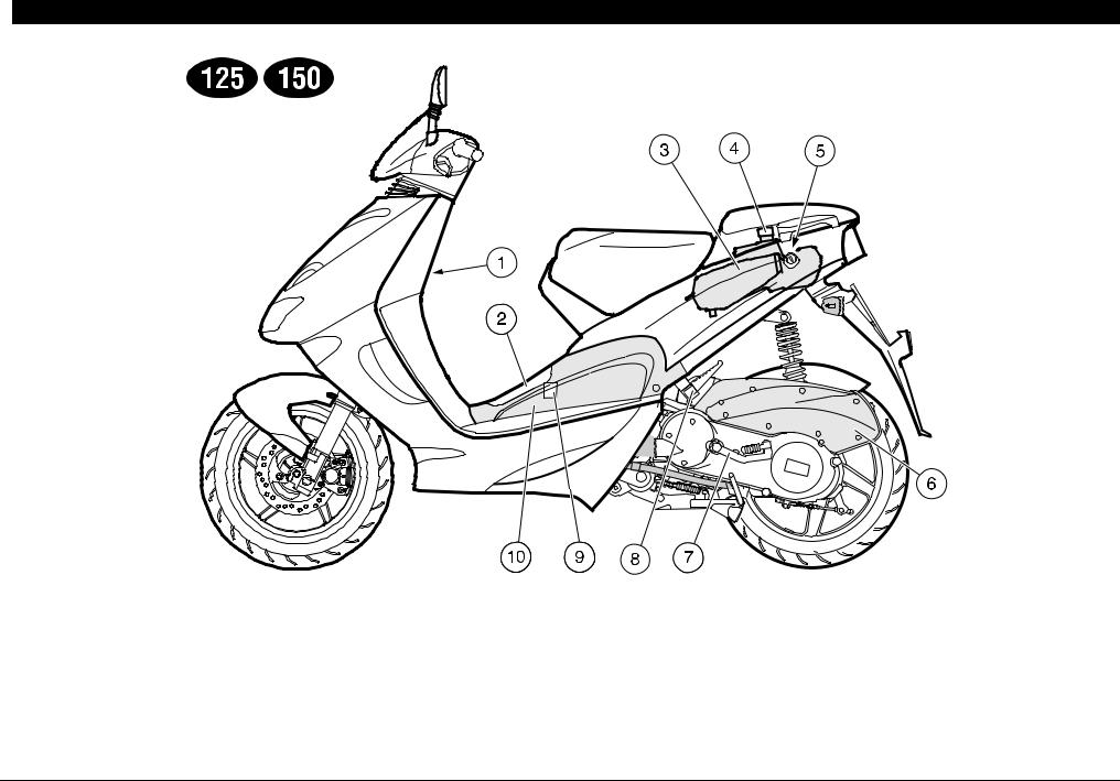
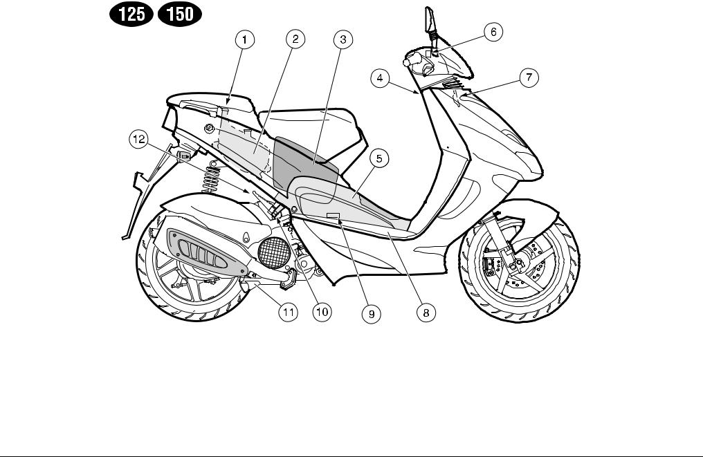
 !22!.'%-%.4 /& 4(% -!). %,%-%.43 • +
|
|
|
|
|
|
|
|
|
|
|
|
|
|
|
|
|
|
|
|
|
|
|
|
|
|
|
|
+%9 |
|
|
|
|
||
1) |
Bag hook |
6) |
Air cleaner |
|||
2) |
Battery/tool kit compartment cover |
7) |
Kick starter |
|||
3) |
Fuel tank |
8) |
Passenger left footrest |
|||
4) |
Fuel tank plug |
9) |
Fuse carrier |
|||
5) |
Saddle lock |
10) |
Left inspection cover |
|||
14 use and maintenance SR 50 - SR 125 - SR 150
|
|
|
|
|
|
|
|
|
|
|
|
|
|
|
|
|
|
|
|
|
|
|
|
|
|
|
|
|
|
|
|
|
|
|
|
|
|
|
|
|
|
|
|
|
|
|
|
|
|
|
|
|
|
|
|
|
|
|
|
|
|
|
|
|
|
|
|
|
|
|
|
|
|
|
|
|
|
|
|
|
|
|
|
|
|
|
|
|
|
|
|
|
|
|
|
|
|
|
|
|
|
|
|
|
|
|
|
|
|
|
|
|
|
|
|
|
|
|
|
|
|
|
|
|
|
|
|
|
|
|
|
|
|
|
|
|
|
|
|
|
|
|
|
|
|
|
|
|
|
|
|
|
|
|
|
|
|
|
|
|
|
|
|
|
|
|
|
|
|
|
|
|
|
|
|
+%9 |
|
|
|
|
|
|
|
|
|
|
|
|
|
||
1) |
2 stroke oil tank plug |
8) |
|
Battery |
|||||||||||
2) |
2 stroke oil tank |
9) |
|
Spark plug |
|||||||||||
3) |
Crash helmet / glove compartment |
10) Anti-theft hook (for the aprilia “Body- |
|||||||||||||
4) |
Ignition switch/steering lock |
|
|
|
|
|
|
Guard” armored cable &). |
|||||||
5) |
Right inspection cover |
11) |
|
Centre stand |
|||||||||||
6) |
Brake fluid reservoir (front brake) |
12) |
|
Passenger right footrest |
|||||||||||
7) |
Horn |
|
|
|
|
|
|
|
|
|
|
|
|||
use and maintenance SR 50 - SR 125 - SR 150 15

!22!.'%-%.4 /& 4(% #/.42/,3 ).3425-%.43 !.$ ).$)#!4/23
|
|
|
|
|
|
|
|
|
|
|
|
|
|
|
|
|
|
|
|
|
|
|
|
|
|
|
|
|
|
|
|
|
|
|
|
|
|
|
|
|
|
|
|
|
|
|
|
|
|
|
|
|
|
|
|
|
|
|
|
|
|
|
|
|
|
|
|
|
|
|
|
|
|
|
|
|
|
|
|
|
|
|
|
|
|
|
|
|
|
|
|
|
|
|
|
|
|
|
|
|
|
|
|
|
|
|
|
|
|
|
|
|
|
|
|
|
|
|
|
|
|
|
|
|
|
|
|
|
|
|
|
|
|
|
|
|
|
|
|
|
|
|
|
|
|
|
|
|
|
|
|
|
|
|
|
|
|
|
|
|
|
|
|
|
|
|
|
|
|
|
|
|
|
|
|
|
|
|
|
|
|
|
|
|
|
|
|
|
|
|
|
|
|
|
|
|
|
|
|
|
|
|
|
|
|
|
|
|
|
|
|
|
|
|
|
|
|
|
|
|
|
|
|
|
|
|
|
|
|
|
|
|
|
|
|
|
|
|
|
|
|
|
|
|
|
|
|
|
|
|
|
|
|
|
|
|
|
|
|
|
|
|
|
|
|
|
|
|
|
|
|
|
|
|
|
|
|
|
|
|
|
|
|
|
|
|
|
|
|
|
|
|
|
|
|
|
|
|
|
|
|
|
|
|
|
|
|
|
|
|
|
|
|
|
|
|
|
|
|
|
|
|
|
|
|
|
|
|
|
|
|
|
|
|
|
|
|
|
|
|
|
|
|
|
|
|
|
|
|
|
|
|
|
|
|
|
|
|
|
|
|
|
|
|
|
|
|
|
|
|
|
|
|
|
|
|
|
|
|
|
|
|
|
|
|
|
|
|
|
|
|
|
|
|
|
|
|
|
|
|
|
|
|
|
|
|
|
|
|
|
|
|
|
|
|
|
|
|
|
|
|
|
|
|
|
|
|
|
|
|
|
|
|
|
|
|
|
|
|
|
|
|
|
|
|
|
|
|
|
|
|
|
|
|
|
|
|
|
|
|
|
|
|
|
|
|
|
|
|
|
|
|
|
|
|
|
|
|
|
|
|
|
|
|
|
|
|
|
|
|
|
|
|
|
|
|
|
|
|
|
|
|
|
|
|
|
|
|
|
|
|
|
|
|
|
|
|
|
|
|
|
|
|
|
|
|
|
|
|
|
|
|
|
|
|
|
|
|
|
|
|
|
|
|
|
|
|
|
|
|
|
|
|
|
|
|
|
|
|
|
|
|
|
|
|
|
|
|
|
|
|
|
|
|
|
|
|
|
|
|
|
|
|
|
|
|
|
|
|
|
|
|
|
|
|
|
|
|
|
|
|
|
|
|
|
|
|
|
|
|
|
|
|
|
|
|
|
|
|
|
|
|
|
|
|
|
|
|
|
|
|
|
|
|
|
|
|
|
|
|
|
|
|
|
|
|
|
|
|
|
|
|
|
|
|
|
|
|
|
|
|
|
|
|
|
|
|
|
|
|
|
|
|
|
|
|
|
|
|
|
|
|
|
|
|
|
|
|
|
|
|
|
|
|
|
|
|
|
|
|
|
|
|
|
|
|
|
|
|
|
|
|
|
|
|
|
|
|
|
|
|
|
|
|
|
|
|
|
|
|
|
|
|
|
|
|
|
|
|
|
|
|
|
|
|
|
|
|
|
|
|
|
|
|
|
|
|
|
|
|
|
|
|
|
|
|
|
|
|
|
|
|
|
|
|
|
|
|
|
|
|
|
|
|
|
|
|
|
|
|
|
|
|
|
|
|
|
|
|
|
|
|
|
|
|
|
|
|
|
|
|
|
|
|
|
|
|
|
|
|
|
|
|
|
|
|
|
|
|
|
|
|
|
|
|
|
|
|
|
|
|
|
|
|
|
|
|
|
|
|
|
|
|
|
+%9 |
|
|
|
|
|
|
|
|
|
|
|
|
|
|
|
|
|
|
|
|
|
|
|
|
|
|
|
|
|
|
|
|
|
|
|
|
|
|
|
|
|
|
||
1) |
Electrical controls on the left side of the handlebar |
10) |
Fuel level indicator (g) |
|||||||||||||||||||||||||||||||||||||||||
2) |
Rear brake lever |
11) |
Speedometer |
|||||||||||||||||||||||||||||||||||||||||
3) |
Left rear-view mirror |
12) |
Total kilometres odometer |
|||||||||||||||||||||||||||||||||||||||||
4) |
Instruments and indicators |
13) |
.Coolant temperature indicator (h) 1 |
|||||||||||||||||||||||||||||||||||||||||
5) |
Right rear-view mirror |
14) |
Green direction indicator warning light (c) |
|||||||||||||||||||||||||||||||||||||||||
6) |
Throttle grip |
15) |
Red 2 stroke oil reserve warning light (j) |
|||||||||||||||||||||||||||||||||||||||||
7) |
Front brake lever |
16) |
.Green low beam warning light (b) |
|||||||||||||||||||||||||||||||||||||||||
8) |
Electrical controls on the right side of the handlebar |
16a) |
.Blue high beam warning light (a) C%K-_ |
|||||||||||||||||||||||||||||||||||||||||
9) |
Ignition switch/steering lock (n - m - s) |
17) |
• +Blue high beam warning light (a) |
|||||||||||||||||||||||||||||||||||||||||
|
|
|
|
|
|
|
|
|
|
|
|
|
|
|
|
|
18) |
Amber low fuel warning light (g) |
||||||||||||||||||||||||||
16 use and maintenance SR 50 - SR 125 - SR 150
).3425-%.4 !.$ ).$)#!4/2 4!",%
Description |
|
Function |
|
|
|
|
|
|
|
|
|
|
|
|
|||||
Direction indicator warning light |
(c) |
It blinks when the direction indicators are on. |
|||||||
|
|
|
|
|
|||||
|
|
It comes on when the ignition switch is in position “n” and the start push button |
|||||||
|
|
“r“ is pressed, thus checking the proper functioning of the bulb. |
|||||||
|
|
If the light does not come on during the starting, provide for replacing the bulb. |
|||||||
2 stroke oil reserve warning light |
(j) |
|
|
If the warning light comes on and does not go out |
|||||
|
aCAUTION |
|
|||||||
|
|
|
|
|
|
|
after the start push button “r” has been released, |
||
|
|
|
|
|
|
|
|||
|
|
or if it comes on during normal functioning, this means that the 2 stroke |
|||||||
|
|
oil reserve is being used; in this case, top up the 2 stroke oil tank, see |
|||||||
|
|
p. 26 (2 STROKE OIL). |
|
|
|
||||
|
|
|
|
|
|||||
Total kilometres odometer |
|
It indicates the total number of kilometres covered. |
|||||||
|
|
|
|
|
|
||||
Speedometer |
|
It indicates the driving speed. |
|
||||||
|
|
|
|
|
|||||
.Low beam warning light |
(b) |
It comes on when the headlight is in low beam position. |
|||||||
|
|
|
|
|
|
|
|
|
|
.High beam warning light |
(a) |
It comes on when the headlight in high beam position. |
|||||||
C%K-_ |
|||||||||
|
|
|
|
|
|||||
• +High beam warning light |
(a) |
It comes on when the headlight in high beam position. |
|||||||
|
|
|
|
|
|||||
Low fuel warning light |
(g) |
It comes on when the quantity of fuel left in the tank is about 2 L. |
|||||||
|
|
|
|
|
|||||
Fuel level indicator |
(g) |
It indicates the approximate fuel level in the tank. |
|||||||
|
|
|
|
|
|||||
|
|
It indicates the approximate temperature of the coolant in the engine. |
|||||||
|
|
When the pointer starts moving beyond the “min” level, the temperature is suffi- |
|||||||
|
|
cient for driving the vehicle. |
|
||||||
.Coolant temperature indicator 1 |
(h) |
The normal running temperature range is indicated by the central area of the |
|||||||
scale. |
|
|
|
|
|
|
|||
|
|
If the pointer reaches the red area, stop the engine and check the coolant level, |
|||||||
|
|
see p. 30 ( |
. |
COOLANT |
1 |
). |
|||
|
|
|
|
||||||
|
|
|
|
|
|
|
If the maximum allowed temperature is exceeded |
||
|
|
|
aCAUTION |
|
|||||
|
|
|
|
(red area “max” of the scale), the engine may be |
|||||
|
|
|
|
|
|
|
|||
|
|
|
|
|
|
|
seriously damaged. |
||
|
|
|
|
|
|
|
|
|
|
|
|
|
|
|
|
|
|
|
|
use and maintenance SR 50 - SR 125 - SR 150 17
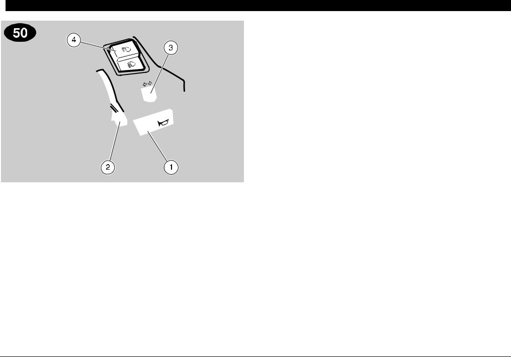
 -!). ).$%0%.$%.4 #/.42/,3 .
#/.42/,3 /. 4(% ,%&4 3)$% /& 4(% (!.$,%"!2
NOTE The electrical parts work only when the ignition switch is in position “n”.
NOTE The lighting system works only when the engine is running.
1) HORN PUSH BUTTON (f)
The horn is activated when the push button is pressed.
2) COLD START LEVER (e)
The starter for the cold start of the engine is operated by rotating the lever downwards.
To disconnect the cold start, bring the lever to its initial position.
3) DIRECTION INDICATOR SWITCH (c)
To indicate the turn to the left, move the switch to the left; to indicate the turn to the right, move the switch to the right.
To turn off the direction indicator, press the switch.
4) DIMMER SWITCH ( a - b)
(in the countries where the engine stop switch is required “m - n”)
When it is in position “b” the parking lights, the dashboard light and the low beam are always on.
When it is in position “a”, the high beam comes on.
NOTE The lights can be switched off only by stopping the engine.
18 use and maintenance SR 50 - SR 125 - SR 150
#/.42/,3 /. 4(% 2)'(4 3)$% /& 4(% (!.$,%"!2
NOTE The electrical parts work only when the ignition switch is in position “n”.
NOTE The lighting system works only when the engine is running.
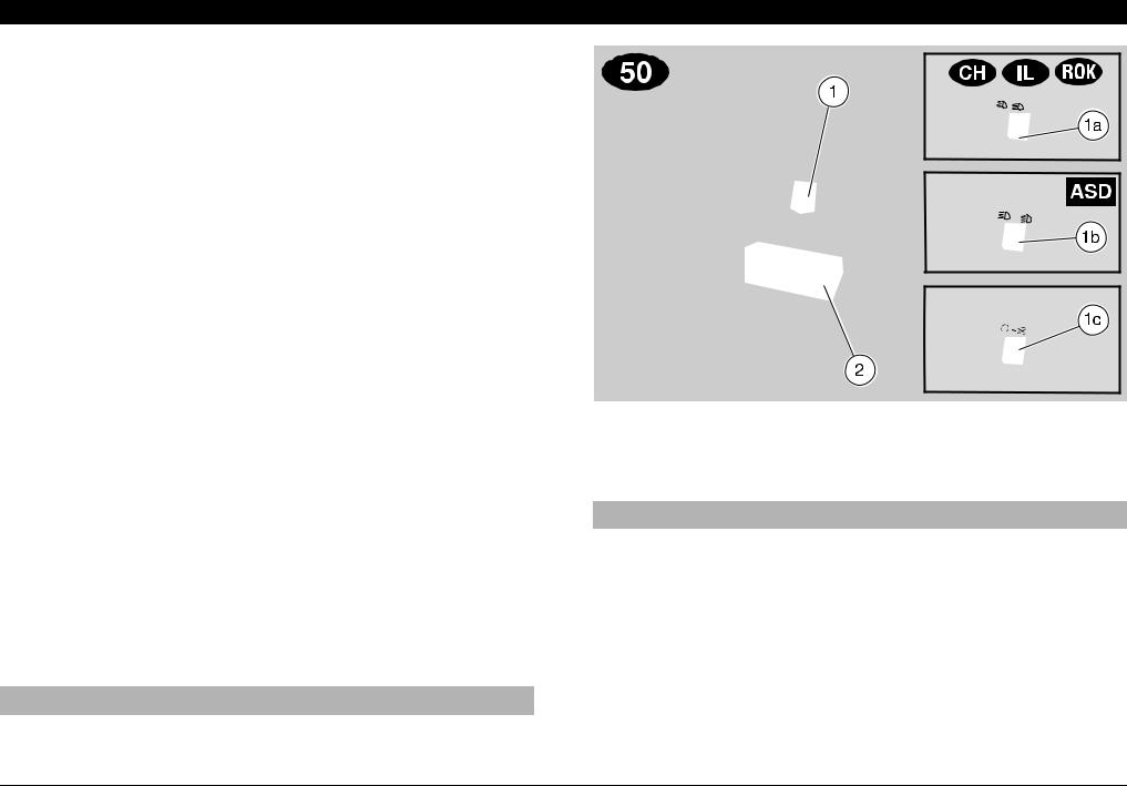
1)LIGHT SWITCH (b - •) (_not provided)
When the light switch is in position “•”, the lights are off; when the switch is in position “b”, the rear parking light and the low beam are on.
1a) LIGHT SWITCH (a - b - •) C%K
When the light switch is in position “•”, the lights are off; when the switch is in position “b” the low beam and the parking lights are on; when it is in position “a” the high beam and the parking lights are on.
1b) DIMMER SWITCH ( a - b) _
(not provided for those countries where the engine stop switch “m - n” is required)
When the dimmer switch is in position “b”, the low beam and the parking lights are on; when it is in position “a”, the high beam and the parking lights are on.
NOTE The lights can be switched off only by stopping the engine.
1c) ENGINE STOP SWITCH (n - m)
(in the countries where required)
aCAUTION
Do not operate the engine stop switch “n - m” in running conditions.
This is a safety or emergency switch. With the switch in position “n”, it is possible to start the engine; the engine can be stopped by moving the switch to position “m”.
aCAUTION
With stopped engine and ignition switch in position “n”, the battery may run down.
When the vehicle has come to a halt, stop the engine, and move the ignition switch to position “m”.
2)START PUSH BUTTON (r)
When the start push button is pressed and one of the brake levers (front or rear) is activated at the same time, the starter makes the engine run.
For the starting procedure, see p. 36 (STARTING).
use and maintenance SR 50 - SR 125 - SR 150 19
 -!). ).$%0%.$%.4 #/.42/,3 • +
#/.42/,3 /. 4(% ,%&4 3)$% /& 4(% (!.$,%"!2
NOTE The electrical parts work only when the ignition switch is in position “n”.
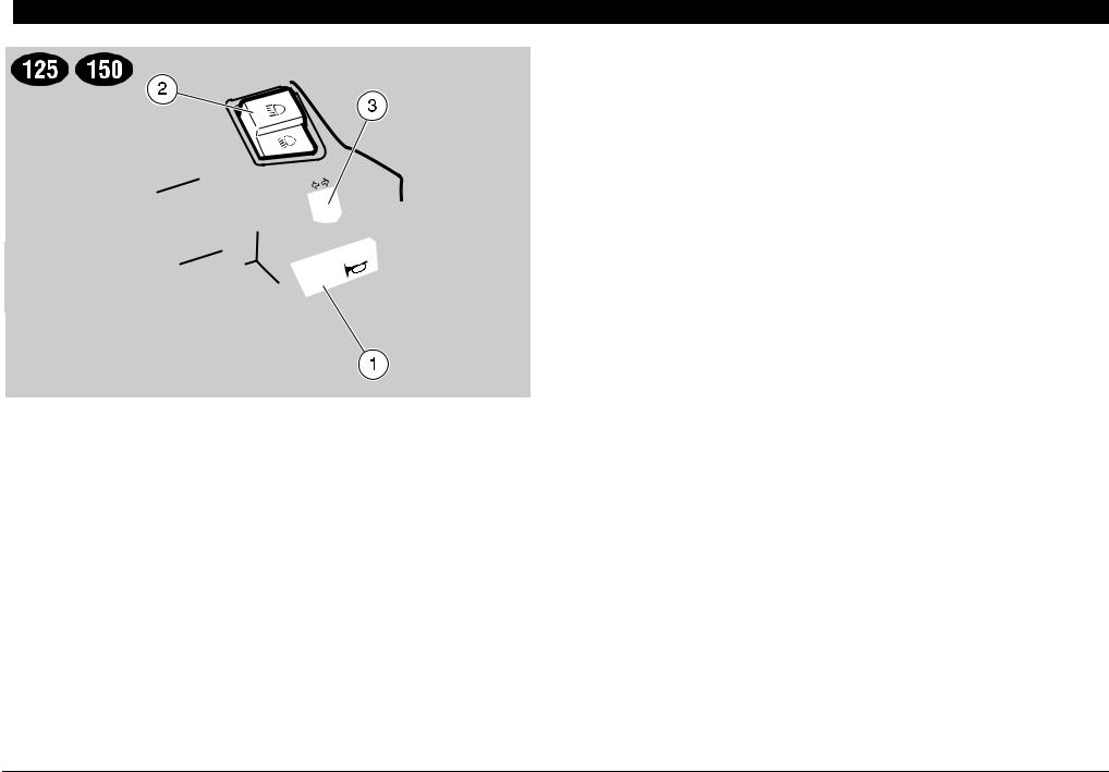
1) HORN PUSH BUTTON (f)
The horn is activated when the push button is pressed.
2) DIMMER SWITCH ( a - b) (_not provided)
When the light switch is in position “o”: if the dimmer switch is in position “a”, the high beam comes on, while if it is in position “b”, the low beam comes on.
3) DIRECTION INDICATOR SWITCH (c)
To indicate the turn to the left, move the switch to the left; to indicate the turn to the right, move the switch to the right.
To turn off the direction indicator, press the switch.
20 use and maintenance SR 50 - SR 125 - SR 150
#/.42/,3 /. 4(% 2)'(4 3)$% /& 4(% (!.$,%"!2
NOTE The electrical parts work only when the ignition switch is in position “n”.
1)LIGHT SWITCH ( o - p- • ) (Jnot provided)
NOTE Before operating the light switch, make sure that the dimmer switch ( a - b ) is in position “b”.
When the light switch is in position “•”, the lights are off; when the switch is in position “p”, the parking lights and the dashboard light are on; when the switch is in position “o”, the parking lights, the dashboard light and the low beam are on. The high beam can be operated by means of the dimmer switch ( a - b).
1a) DIMMER SWITCH ( a - b ) _
When it is in position “b” the parking lights, the dashboard light and the low beam are always on.
When it is in position “a”, the high beam comes on.
2)START PUSH BUTTON (r)
When the start push button is pressed and one of the brake levers (front or rear) is activated at the same time, the starter makes the engine run.
For the starting procedure, see p. 36 (STARTING).
use and maintenance SR 50 - SR 125 - SR 150 21
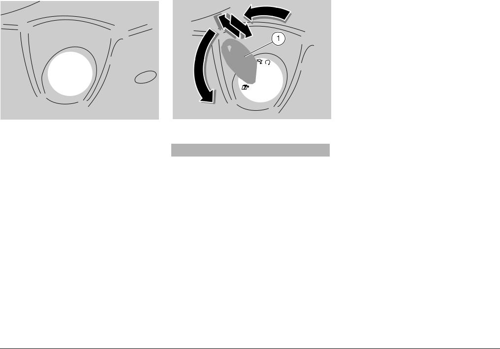
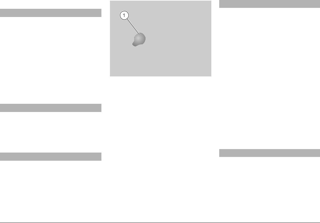
)'.)4)/. 37)4#(
The ignition switch is positioned on the right side, near the steering column.
NOTE The key (1) operates the ignition/steering lock switch, the battery/tool kit compartment lock and the saddle lock.
Two keys are supplied together with the vehicle (one spare key).
NOTE Do not keep the spare key on the vehicle.
34%%2).' ,/#+
aWARNING
Never turn the key to position “s” in running conditions, in order to avoid losing control of the vehicle.
OPERATION
To lock the steering:
Turn the handlebar completely leftwards.
Turn the key (1) to position “m” and press it.
Release the key.
NOTE Turn the key and steer the handlebar at the same time.
Rotate the key (1) anticlockwise (leftwards), steer the handlebar slowly until the key (1) reaches position “s”.
Extract the key.
Position |
Function |
Key |
|
removal |
|||
|
|
||
|
|
|
|
|
The steering |
It is possible |
|
s |
is locked. |
to remove |
|
It is neither |
the key. |
||
Steering |
possible to |
|
|
start the en- |
|
||
lock |
gine, nor to |
|
|
|
switch on the |
|
|
|
lights. |
|
|
|
|
|
|
|
Neither the |
It is possible |
|
m |
engine, nor |
to remove |
|
the lights can |
the key. |
||
|
be switched |
|
|
|
on. |
|
|
|
|
|
|
|
The engine |
It is not pos- |
|
n |
and the lights |
sible to re- |
|
can be |
move the |
||
|
switched on. |
key. |
|
|
|
|
22 use and maintenance SR 50 - SR 125 - SR 150
 !58),)!29 %15)0-%.4
5.,/#+).' ,/#+).' 4(% 3!$$,%
To unlock and lift the saddle:
Position the vehicle on the stand.
Insert the key in the saddle lock (1).
Turn the key clockwise and raise the saddle (2).
NOTE Before lowering and locking the saddle, make sure that you have not left the key in the crash helmet / glove compartment.
To lock the saddle, lower and press it (without exerting too much pressure), thus making the lock snap shut.
aWARNING
Before leaving, make sure that the saddle is properly locked.
#2!3( (%,-%4 ',/6% #/-0!24-%.4
Thanks to the crash helmet/glove compartment, you no longer have to carry the crash helmet or other objects with you every time you park the vehicle. The compartment is positioned under the saddle.
To reach it:
Raise the saddle (2), see beside (UNLOCKING / LOCKING THE SADDLE).
NOTE Position the helmet with the opening facing downwards, as indicated in the figure.
aWARNING
Do not load the crash helmet / glove compartment too much.
Maximum allowed weight: 2.5 kg.
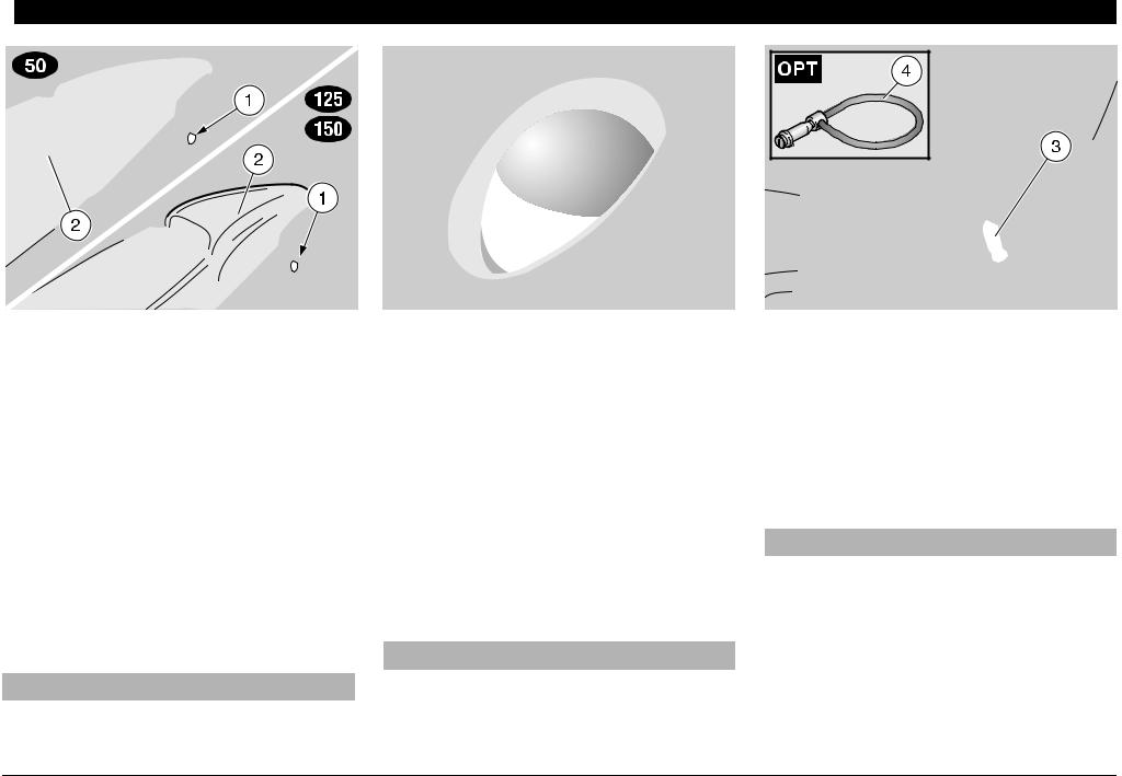
!.4) 4(%&4 (//+
The anti-theft hook (3) is positioned on the right side of the vehicle, near the rider’s footboard.
To prevent the vehicle from being stolen, it is advisable to secure it with the aprilia “Body-Guard” armored cable &(4), available at any aprilia Official Dealer.
aWARNING
Do not use the hook to lift the vehicle or for any purpose other than securing the vehicle once it has been parked.
use and maintenance SR 50 - SR 125 - SR 150 23
"!44%29 4//, +)4 #/-0!24-%.4
This compartment is positioned in the lower part of the vehicle, between the footrests.
To reach it, proceed as follows:
Insert the key (1) in the lock.
Rotate the key (1) clockwise, pull it and remove the cover (2).
The tool kit (3) includes:
–n. 1 tool case
–n. 1 21 mm spark plug socket spanner
–n. 1 socket spanner rod
–n. 1 double-ended, cross-/cut headedscrewdriver type PH size 2
–n. 1 screwdriver handle
–n. 1 .4 mm hexagon spanner
–n. 1 .8/10 mm socket spanner
"!' (//+
aWARNING
Do not hang excessively bulky bags or parcels to the hook, as this may seriously compromise the manoeuvrability of the vehicle or the movement of your feet.
The bag hook (4) is positioned on the front part of the inner shield.
Max. allowed weight: 1.5 kg.
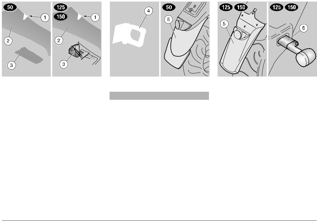
2%!2 -5$'5!2$ %84%.3)/.
The rear mudguard extension (5) is provided as standard equipment and can be installed if the vehicle is used on wet roads, since it reduces the reach of the water spray caused by the rear wheel.
NOTE The rear mudguard extension (5), complete with screws and relevant nuts, is supplied as standard equipment and is
housed in the crash helmet/glove compartment.
For the installation, see p. 56 (.INSTALLING THE REAR MUDGUARD EXTENSION), see p. 57 (• + INSTALLING THE REAR MUDGUARD EXTENSION).
• +$)2%#4)/. ).$)#!4/2
%84%.3)/.3
In the countries where the number plate size is 280x280 mm, it is necessary to install appropriate extensions (6) for the direction indicators.
NOTE The direction indicator extensions (6), complete with nuts and screws, are supplied as standard equipment and are housed in the crash helmet/glove compartment.
For the installation, see p. 58 (• + INSTALLING THE DIRECTION INDICATOR EXTENSIONS).
24 use and maintenance SR 50 - SR 125 - SR 150

 -!). #/-0/.%.43
&5%,
aWARNING
The fuel used for internal combustion engines is extremely inflammable and in particular conditions it can become explosive. It is important to carry out the refuelling and the maintenance operations in a well-ventilated area, with the engine off. Do not smoke while refuelling or near fuel vapours, in any case avoid any contact with naked flames, sparks and any other heat source to prevent the fuel from catching fire or from exploding.
Further, prevent fuel from flowing out of the fuel filler, as it could catch fire when getting in contact with the red-hot surfaces of the engine.
In case some fuel has accidentally been spilt, make sure that the area is completely dry before starting the vehicle.
Since petrol expands under the heat of the sun and due to the effects of sun radiation, never fill the tank to the brim.
Screw the cap carefully after refuelling. Avoid any contact of the fuel with the skin and the inhalation of vapours; do not swallow fuel or pour it from a receptacle into another by means of a tube.
DO NOT DISPOSE OF FUEL IN THE ENVIRONMENT.
KEEP AWAY FROM CHILDREN.
.
Use only premium grade petrol (4 Stars U), in conformity with the DIN 51600 standard, min. O.N. 98 (N.O.R.M.) and 88 (N.O.M.M.).
2Use only unleaded petrol, in conformity with the DIN 51607 standard, min. O.N. 95 (N.O.R.M.) and 85 (N.O.M.M.).
•+
Use only unleaded petrol, in conformity with the DIN 51607 standard, min. O.N. 95 (N.O.R.M.) and 85 (N.O.M.M.).
FUEL TANK CAPACITY (reserve included): 8 L
TANK RESERVE: 2 L
To refuel, proceed as follows:
Position the vehicle on the centre stand.
Lift the saddle, see p. 23 (UNLOCKING / LOCKING THE SADDLE).
Unscrew and remove the fuel tank plug
(1).
Refuel.
aWARNING
After refuelling, put back the cap (1) in the correct position.
Put back the cap (1).
use and maintenance SR 50 - SR 125 - SR 150 25
,5"2)#!.43
aWARNING
Oil can cause serious damage to the skin if handled every day and for long periods.
Wash your hands carefully after using oil.
In case any maintenance operation has to be carried out, it is advisable to use latex gloves.
KEEP AWAY FROM CHILDREN.
DO NOT DISPOSE OF OIL IN THE ENVIRONMENT.
aCAUTION
Proceed with care. Do not spill the oil!
Take care not to smear any component, the area in which you are working and the surrounding area.
Carefully remove any trace of oil.
aCAUTION
In case of leakages or malfunctions, contact an APRILIA Official Dealer.
2 STROKE OIL
Top up the 2 stroke oil tank every 500 km (312 mi).
The vehicle is provided with a separate mixer that makes it possible to mix petrol with oil for the lubrication of the engine, see p. 84 (x LUBRICANT CHART) or p. 85 (z{LUBRICANT CHART).
The reserve is indicated by the coming on of the 2 stroke oil reserve warning light “j” positioned on the dashboard, see p. 16 and 17 (ARRANGEMENT OF THE CONTROLS / INSTRUMENTS AND INDICATORS).
aCAUTION
The use of the vehicle without 2 stroke oil causes serious damages to the engine.
If you run out of oil in the 2 stroke oil tank or if the 2 stroke oil pipe has been
removed, it is necessary to contact an APRILIA Official Dealer, who will provide
for bleeding the system.
This operation is indispensable, since the operation of the engine with air in the 2 stroke oil system may cause serious damages to the engine itself.
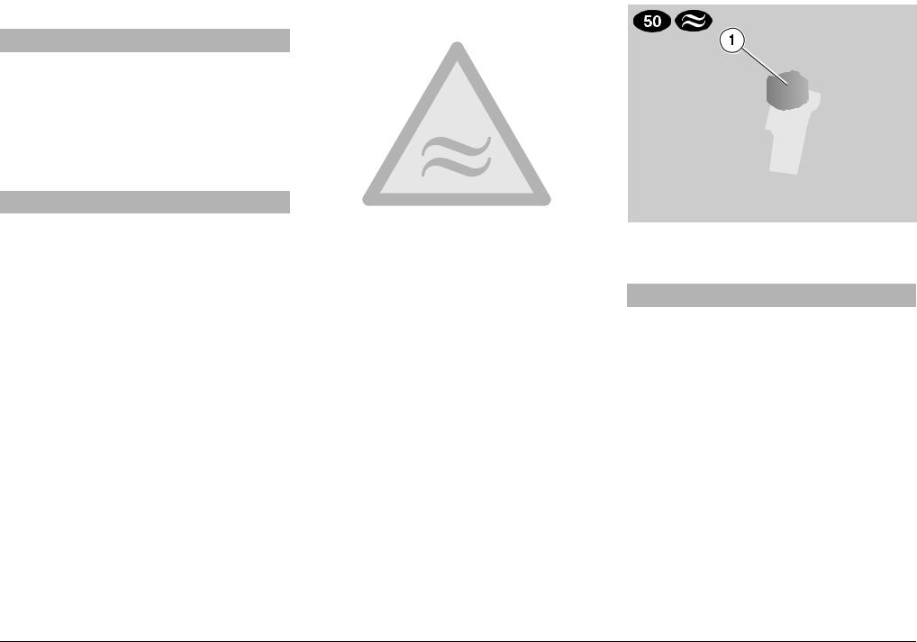
To top up the 2 stroke oil tank, proceed as follows:
Position the vehicle on the centre stand.
Lift the saddle, see p. 23 (UNLOCKING / LOCKING THE SADDLE).
Remove the plug (1).
2 STROKE OIL TANK CAPACITY: 1.6 L
TANK RESERVE: 0.5 L
Top up the 2 stroke oil tank.
aWARNING
After refuelling, put back the cap (1) in the correct position.
Put back the cap (1).
26 use and maintenance SR 50 - SR 125 - SR 150
.TRANSMISSION OIL
Have the transmission oil level checked every 4000 km (2500 mi), or every 12 months.
It is necessary to have the transmission oil changed after the first 500 km (312 mi) and successively every 12000 km (7500 mi), or every 2 years.
To check the oil level and to change the oil, contact an aprilia Official Dealer.
•+TRANSMISSION OIL
Have the transmission oil level checked every 4000 km (2500 mi), or every 12 months.
It is necessary to have the transmission oil changed after the first 1000km (625 mi) and successively every 12000 km (7500 mi), or every 24 months.
To check the oil level and to change the oil, contact an aprilia Official Dealer.
"2!+% &,5)$ RECOMMENDATIONS
aWARNING
Sudden resistance or clearance problems on the brake lever may be due to troubles in the hydraulic system.
For any doubt regarding the perfect functioning of the braking system and in case you are not able to carry out the
usual checking operations, contact your APRILIA Official Dealer.
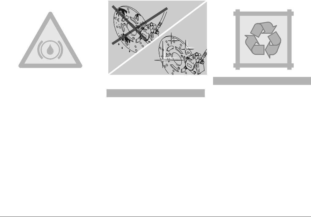
aWARNING
Pay special attention to the brake disc and friction material, making sure that they are neither dirty nor oily, especially after maintenance operations or inspections.
Make sure that the brake pipe is neither twisted nor worn out.
KEEP AWAY FROM CHILDREN.
DO NOT DISPOSE OF THE FLUID IN THE ENVIRONMENT.
use and maintenance SR 50 - SR 125 - SR 150 27
$)3# "2!+%3
aWARNING
The brakes are the parts that most ensure your safety and for this reason they must always be perfectly working; check them before every trip.
A dirty disc soils the pads, with consequent reduction of the braking efficiency. Dirty pads must be replaced, while dirty discs must be cleaned with a highquality degreaser.
The brake fluid must be changed every two years by an APRILIA Official Dealer.
For any doubt regarding the perfect functioning of the braking system and in case you are not able to carry out the
usual checking operations, contact your APRILIA Official Dealer.
This vehicle is provided with hydraulic disc brakes.
NOTE For the version with rear drum brake 3, the following information refers to the front disc brake only.
When the disc pads wear out, the level of the fluid decreases to automatically compensate for their wear.
The brake fluid reservoir (1) is positioned near the front brake lever coupling. Periodically check the brake fluid level in the reservoir (1) and the pad wear, see p. 51 (CHECKING THE BRAKE PAD WEAR).
aWARNING
Do not use the vehicle if the braking system leaks fluid.
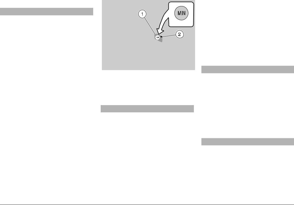
CHECKING
To check the brake fluid level, proceed as follows:
NOTE Position the vehicle on firm and flat ground.
MIN = minimum level.
Position the vehicle on the centre stand.
Rotate the handlebar, so that the fluid contained in the brake reservoir is parallel to the “MIN” mark stamped on the glass gauge (2).
Make sure that the fluid contained in the reservoir exceeds the “MIN” mark stamped on the glass gauge (2).
If the fluid does not reach at least the “MIN” mark:
aCAUTION
When the disc pads wear out, the level of the fluid decreases progressively to compensate for their wear.
Check the brake pad wear, see p. 51 (CHECKING THE BRAKE PAD WEAR) and the disc wear.
If the pads and / or the disc do not need replacing:
Contact an aprilia Official Dealer, who will provide for topping up.
aCAUTION
Check the braking efficiency.
In case of excessive stroke of the brake lever or reduced efficiency of the braking system, contact an APRILIA Official Dealer, since it may be necessary to bleed the system.
28 use and maintenance SR 50 - SR 125 - SR 150
2%!2 $25- "2!+%
aWARNING
The brakes are the parts that most ensure your safety and for this reason they must always be perfectly working.
For any doubt regarding the perfect functioning of the braking system and in case you are not able to carry out the
usual checking opAerations, contact your APRILIA Official Dealer.
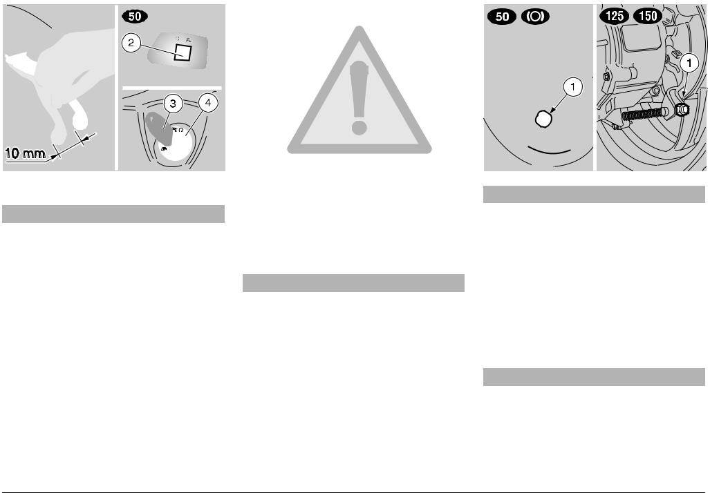
ADJUSTING THE BRAKE
Measure the distance covered by the lever before the brake starts it braking action. The idle stroke at the end of the brake lever must be about 10 mm.
To adjust the clearance, proceed as follows:
Act on the adjuster (1).
Put on the brake repeatedly and make sure that the wheel turns freely after the brake has been released.
Check the braking efficiency.
aWARNING
If the adjuster (1) can be screwed up completely, this means that the brake shoes are worn out.
In this case, see p. 51 (CHECKING THE SHOE WEAR).
NOTE The heating of the brake shoes caused by the braking action may modify the clearance between the friction material and the drum. For this reason, it is advisable to check the clearance even with the shoes at operating temperature.
Carry out a trial run operating the rear brake two or three times.
aWARNING
Carry out this check with the engine at rest.
Stop the vehicle, see p. 41 (STOPPING).
. Move the engine stop switch (2) to position “m” (for the countries where required).
Rotate the key (3) and move the ignition switch (4) to position “m”.
Position the vehicle on the centrestand.
Make sure that the wheel turns freely.
If necessary:
aWARNING
When the engine is hot, be careful not to burn yourself while carrying out the following operations.
Loosen the adjuster (1), making sure that the wheel turns freely.
use and maintenance SR 50 - SR 125 - SR 150 29
.#//,!.4 1
aCAUTION
Do not use the vehicle if the coolant is below the minimum prescribed level “MIN”.
Check the coolant level every 2000 km (1250 mi) and after long trips; have the coolant changed by an aprilia Official Dealer every 2 years.
aWARNING
The coolant is noxious: do not swallow it; if the coolant gets in contact with the skin or the eyes, it can cause serious irritations.
If the coolant gets in contact with your skin or eyes, rinse with plenty of water and consult a doctor. If it is swallowed, induce vomit, rinse mouth and throat with plenty of water and consult a doctor without delay.
DO NOT DISPOSE OF THE FLUID IN THE ENVIRONMENT.
KEEP AWAY FROM CHILDREN.
Be careful not to spill the coolant on the red-hot parts of the engine: it may catch fire and send out invisible flames.
In case maintenance operations are to be performed, it is advisable to use latex gloves.
Have the coolant changed by an APRILIA Official Dealer.
The coolant is made up of 50% water and 50% antifreeze.
This mixture is ideal for most running temperatures and ensures good protection against corrosion.
It is advisable to keep the same mixture also in the hot season, since in this way losses due to evaporation are reduced and it is not necessary to top up very frequently.
The mineral salt deposits left in the radiator by evaporated water are thus reduced and the efficiency of the cooling system remains unchanged.
If the outdoor temperature is below 0°C, check the cooling circuit frequently and if necessary increase the antifreeze concentration (up to maximum 60%).
For the cooling solution use distilled water, in order not to damage the engine.
aWARNING
Do not remove the expansion tank cap
(1) when the engine is hot, since the coolant is under pressure and its temperature is high.
If it gets in contact with the skin or with clothes it may cause severe burns and/or damage.
30 use and maintenance SR 50 - SR 125 - SR 150
 Loading...