


ご覧になればaprilia
APRILIA WOULD LIKE TO THANK YOU
for choosing one of its products. We have drawn up this booklet to provide a comprehensive overview of your vehicle's quality features. Please read it carefully before riding the vehicle for the first time. It contains information, tips and precautions for using your vehicle. It also describes features, details and devices to assure you that you have made the right choice. We believe that if you follow our suggestions, you will soon get to know your new vehicle well and will use it for a long time at full satisfaction. This booklet is an integral part of the vehicle, and should the vehicle be sold, it must be transferred to the new owner.
SPORTCITY CUBE 250-300
Ed. 05 2010
さい。
The instructions in this booklet have been compiled primarily to offer a simple and clear guide to using the vehicle; it also describes routine maintenance procedures and regular checks that should be carried out on the vehicle at an Aprilia Dealer or Authorised Workshop. This booklet also contains instructions for simple repairs. Any operations not specifically described in this booklet require the use of special tools and/or particular technical knowledge; for these operations, please take your vehicle to an Aprilia Dealer or Authorised Workshop.
2

|
Personal safety |
|
Failure to completely observe these instruc |
|
tions will result in serious risk of personal |
|
injury. |
|
Safeguarding the environment |
|
Sections marked with this symbol indicate the |
|
correct use of the vehicle to prevent damaging |
|
the environment. |
|
Vehicle intactness |
|
The incomplete or non-observance of these reg |
|
ulations leads to the risk of serious damage to |
|
the vehicle and sometimes even the invalidity |
|
of the guarantee. |
|
The symbols illustrated above are very impor |
|
tant. They are used to highlight parts of the |
|
booklet that should be read with particular |
|
care. The different symbols are used to make |
|
each topic in the manual simple and quick to |
|
locate. Before starting the engine, read this |
|
booklet carefully, particularly the "SAFE RID |
|
ING" section. Your safety as well as other's |
|
does not only depend on the quickness of your |
|
reflexes and agility, but also on how well you |
|
know your vehicle, the state of maintenance of |
|
the vehicle itself and your knowledge of the |
|
rules for SAFE RIDING. For your safety, get to |
|
know your vehicle well so as to safely ride and |
|
master it given any riding condition. IMPORTANT |
|
This booklet is an integral part of the vehicle, |
|
and must be handed to the new owner in the event |
|
of sale. |
3
4
|
|
|
|
|
|
|
INDEX |
.................................................. |
7 |
GENERAL RULES.............................................. |
7 |
................................ |
8 |
Information to recycle the scooter....................... |
8 |
...................................................... |
11 |
VEHICLE.................................................... |
11 |
................................ |
14 |
Arrangement of the main components....................... |
14 |
.......................................... |
15 |
Dashboard................................................ |
15 |
........................ |
17 |
Analogue instrument panel................................ |
17 |
.................................. |
22 |
Digital lcd display...................................... |
22 |
MODO ............................................. |
23 |
"MODE" button.......................................... |
23 |
............................................ |
23 |
Key switch............................................... |
23 |
........................................ |
24 |
Locking the steering wheel............................. |
24 |
............................ |
25 |
Switch direction indicators.............................. |
25 |
.................................................. |
26 |
Horn button.............................................. |
26 |
.......................................... |
26 |
Light switch............................................. |
26 |
........................................ |
27 |
Start-up button.......................................... |
27 |
............................................ |
27 |
Engine stop button....................................... |
27 |
............................................ |
28 |
Power supply socket...................................... |
28 |
...................................... |
29 |
Opening the saddle..................................... |
29 |
.................................................... |
30 |
Identification........................................... |
30 |
............................ |
32 |
Rear top box opening..................................... |
32 |
.......................................... |
32 |
Bag clip................................................. |
32 |
...................................................... |
35 |
USE........................................................ |
35 |
................................................ |
36 |
Checks................................................... |
36 |
.................................................... |
38 |
Refuelling............................................... |
38 |
...................... |
40 |
Shock absorber adjustment................................ |
40 |
............................................ |
42 |
Starting up the engine................................... |
42 |
............................................ |
50 |
Difficult start up....................................... |
50 |
............................................ |
53 |
Stopping the engine...................................... |
53 |
.......................... |
55 |
Catalytic silencer....................................... |
55 |
................................................ |
56 |
Stand.................................................... |
56 |
.............................. |
57 |
Suggestions to prevent theft............................. |
57 |
................................................ |
58 |
Safe driving............................................. |
58 |
5
.............................................. |
65 |
.................................. |
66 |
............................ |
67 |
.................................. |
69 |
...................................... |
70 |
.................................................. |
72 |
................................ |
74 |
................................ |
79 |
............................ |
79 |
........................................ |
81 |
.................................. |
86 |
.............................................. |
89 |
.................................. |
94 |
.................................... |
96 |
................................................ |
97 |
.................................................. |
101 |
.................................. |
103 |
.................................... |
106 |
............................ |
107 |
.................................... |
110 |
.................................... |
112 |
............................................ |
112 |
.......................... |
113 |
...................................... |
116 |
.................................................... |
118 |
.................................................... |
121 |
...................................................... |
125 |
.............................................. |
131 |
.................................. |
133 |
.............................. |
134 |
........................................ |
141 |
MAINTENANCE................................................ |
65 |
Engine oil level......................................... |
66 |
Engine oil level check................................. |
67 |
Engine oil top-up...................................... |
69 |
Hub oil level............................................ |
70 |
Tyres.................................................... |
72 |
Spark plug dismantlement................................. |
74 |
Removing the air filter.................................. |
79 |
Air filter cleaning...................................... |
79 |
Cooling fluid level...................................... |
81 |
Checking the brake oil level............................. |
86 |
Battery.................................................. |
89 |
Use of a new battery................................... |
94 |
Long periods of inactivity............................... |
96 |
Fuses.................................................... |
97 |
Lamps.................................................... |
101 |
Front light group........................................ |
103 |
Headlight adjustment................................... |
106 |
Front direction indicators............................... |
107 |
Rear optical unit........................................ |
110 |
Number plate light....................................... |
112 |
Idle adjustment.......................................... |
112 |
Front and rear disc brake................................ |
113 |
Periods of inactivity.................................... |
116 |
Cleaning the vehicle..................................... |
118 |
Transport................................................ |
121 |
TECHNICAL DATA............................................. |
125 |
Kit equipment............................................ |
131 |
PROGRAMMED MAINTENANCE..................................... |
133 |
Scheduled maintenance table.............................. |
134 |
SPECIAL FITTINGS........................................... |
141 |
SPECIAL FITTINGS........................................... |
142 |
6

SPORTCITY CUBE 250-300
01
Chap. 01 General rules
7

1 / 1 General rules
|
|
Information to recycle the |
|
||
|
(01_01, 01_02) |
scooter (01_01, 01_02) |
|
|
VEHICLE SCRAPPING |
|
|
If the vehicle must be scrapped, |
|
|
contact your nearest "Vehicles Dis |
|
|
posal Centre". |
|
∙ |
∙ Vehicles Disposal Centres |
|
|
These centres are specifically used |
01_01 |
|
to correctly treat the vehicles |
|
|
scrapping, they are registered by |
|
|
the Japan Mini Vehicles Association |
|
: " " |
as centres for the specific treat |
|
∙ |
ment of scrapping material on a |
|
large scale. These centres show the |
|
|
|
|
|
|
following wording: "Authorised cen |
|
|
tre for vehicles disposal". |
|
" " |
∙ Vehicle recycling cost |
|
|
The proper recycling process of ve |
|
|
hicle to be scrapped has a cost. |
|
|
|
01_02 |
|
If the vehicle is equipped with the |
|
|
seal "Vehicles recycling", the re |
|
cycling fee should not be paid be |
|
|
|
cause the cost is already included |
|
|
in the retail price suggested by the |
|
|
manufacturer. |
|
|
|
|
|
Transportation and collection costs, |
|
∙ " " |
however, are not included. There |
|
fore, the collection costs from the |
|
|
|
|
|
" " |
customer and the transportation |
|
|
costs to the disposal centres or to |
|
|
the designated collection centres |
|
|
are charged to the customer. As re |
|
" " |
|
8
http://www.jarc.or.jp/
03-3598-8075
: 9:30 am 5:00 pm
gards this, request information to the nearest scrapping centre.
∙"Vehicle recycling" seal
This vehicle has the "Vehicle recy cling" seal. When scrapping, it is necessary to check this seal. Never delete it from the vehicle body. The seal cannot be reassigned or sold separately after purchase, even if damaged.
∙Position of the recycling seal
It is usually located close to the chassis number or under the seat.
∙Questions regarding the ve hicle scrapping
Contact your nearest vehicle dis posal centre or the following or ganisations.
Japan Automobile Recycling Promotion
Centre
Home page: http://www.jarc.or.jp/
Japan Automobile Recycling Promotion Centre call centre for vehicles re cycling
Telephone: 03-3598-8075
Time: From 9:30 am to 5:00 pm (Except holidays, weekends and the first and last day of the year.)
rules General 1 / 1
9
1 / 1 General rules
10
SPORTCITY CUBE 250-300
02
Chap. 02 Vehicle
11

2 / 2 Vehicle
02_01
12
Vehicle 2 / 2
02_02
13
2 / 2 Vehicle
|
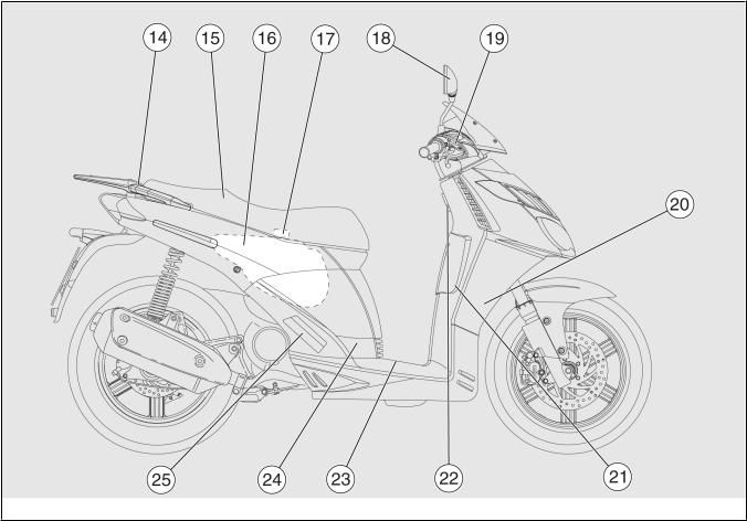
Arrangement of the main |
||||
(02_02) |
components (02_02) |
||||
|
KEY: |
|
|||
1. |
|
1. |
Expansion tank |
||
2. |
|
|
2. |
Coolant expansion tank cap |
|
|
3. |
Rear brake fluid reservoir |
|||
|
|
|
|||
3. |
|
4. |
Left rear-view mirror |
||
|
|
|
|||
4. |
|
5. |
Bag hook |
||
|
|
|
|||
5. |
|
6. |
Air filter |
||
|
|
|
|||
6. |
|
7. |
Centre stand |
||
|
|
|
|||
7. |
|
8. |
Engine oil refill cap |
||
|
|
|
|||
8. |
|
9. |
Passenger left footrest |
||
|
|
|
|||
9. |
|
10. |
Battery |
||
|
|
|
|||
10. |
|
11. |
Fuse box |
||
|
|
|
|||
11. |
|
12. |
Chassis number |
||
|
|
|
|||
12. |
|
13. |
Front case |
||
|
|
|
|||
13. |
|
14. |
Passenger grab handle |
||
|
|
|
|||
14. |
|
15. |
Saddle |
||
|
|
|
|||
15. |
|
16. |
Fuel tank |
||
|
|
|
|||
16. |
|
17. |
Fuel tank cap |
||
|
|
|
|||
17. |
|
18. |
Right rear-view mirror |
||
|
|
|
|||
18. |
|
19. |
Front brake fluid reservoir |
||
|
|
|
|||
19. |
|
20. |
Horn |
||
|
|
|
|||
20. |
|
21. |
Glove-box |
||
|
|
|
|||
14
21. |
|
22. |
Ignition switch /steering lock |
22. |
|
23. |
Battery compartment cover |
|
24. |
Spark plug |
|
|
|
||
23. |
|
25. |
Right passenger footrest |
|
|
||
(02_03) |
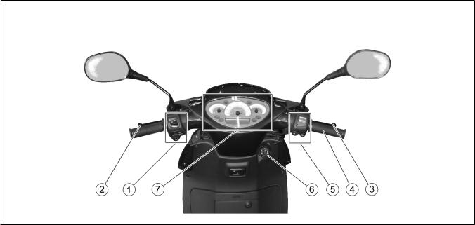
Dashboard (02_03) |
||
|
KEY |
||
1. |
|
1. |
Electrical controls on the left- |
|
hand side of the handlebars |
||
2. |
|
2. |
Rear brake lever |
3. |
|
3. |
Front brake lever |
4. |
|
4. |
Throttle grip |
5. |
|
5. |
Electrical controls on the right- |
|
hand side of the handlebars |
||
6. |
|
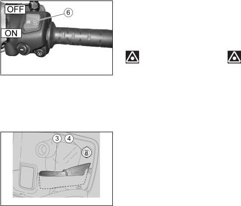
6 Ignition / steering lock switch |
|
ON - OFF - LOCK |
(ON - OFF - LOCK) |
||
7. |
|
7. |
Instruments and gauges |
Vehicle 2 / 2
15
02_03
2 / 2 Vehicle
16
Vehicle 2 / 2
|
|
|
02_04 |
|
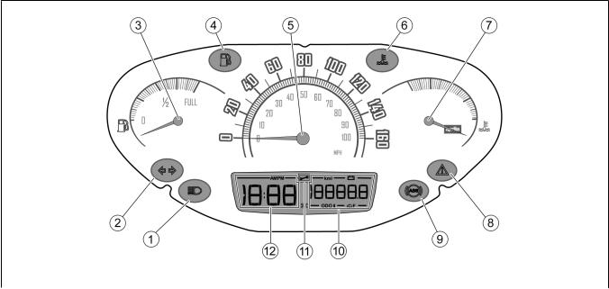
Analogue instrument panel |
||
(02_04) |
(02_04) |
||
|
KEY |
|
|
1. |
|
1. |
High-beam warning light, blue |
2. |
|
2. |
Turn indicator warning light, |
|
green |
||
3. |
|
3. |
Fuel gauge |
4. |
|
4. |
Low fuel warning light, orange |
17

2 / 2 Vehicle
9.ABS ABS
10. メーター(ODO 2ODO I - ODO II
«ON» 3
«1»
5.Speedometer
6.Coolant high temperature warning light
7.Coolant temperature indicator
8.Engine oil pressure warning light / electronic injection control warning light, red
9.ABS warning light (Active only in models with ABS)
10.Multifunction indicator: total odometer (ODO) / two trip odometers (ODO I - ODO II) / battery voltage
11.Not active warning light
12.Digital clock
INSTRUMENT AND GAUGE DESCRIPTION
NOTE
WITH THE KEY SET TO «ON», ALL THE PRE-INSTALLED WARNING LIGHTS, IN STRUMENT PANEL LIGHTING AND ALL THE INDICATORS IN DIGITAL DISPLAY TURN ON FOR THE FIRST THREE SECONDS FOR AN INITIAL INSTRUMENT CHECK.
High-beam warning light «1»
Turns on when the front headlamp high-beam bulb is activated or when
18
|
the high-beam light is flashed |
|
(PASSING). |
«2» |
Turn indicator warning light «2» |
|
Flashes when in right or left turn |
|
ing mode. |
|
If the turn indicator breaks down, |
2 |
the warning light flashing frequency |
|
doubles. Replace light bulb if this |
|
occurs. |
«3» |
Fuel gauge «3» |
|
Shows the approximate fuel level in |
|
the tank. |
«4» |
Low fuel warning light «4» |
1.5 |
Turns on when there is a 1.5-litre |
|
fuel reserve in the tank. |
|
If this occurs, refill the tank as |
|
soon as possible. |
«5» |
Speedometer «5» |
|
Shows riding speed. |
Vehicle 2 / 2
19

2 / 2 Vehicle
«6» |
Coolant high temperature warning |
||
|
light «6» |
|
|
|
Turns on when the coolant tempera |
||
|
ture indicator reaches very high |
||
|
values. Stop the engine at once and |
||
|
|
check the coolant level. |
|
«7» |
Coolant temperature gauge «7» |
|
|
|
Shows the approximate temperature of |
||
|
the coolant in the engine. The nor |
||
|
mal operating temperature is reached |
||
|
when the needle is at central area of |
||
|
the scale. If it is not at the cen |
||
|
tral area, do not over demand the |
||
|
scooter. If the needle reaches |
the |
|
|
|
last segment, stop the engine |
and |
|
|
||
|
check the coolant level. |
|
|
|
|
|
|
|
|
|
|
|
|
CAUTION |
|
|
|
|
|
|
|
|
|
|
IF THE TEMPERATURE EXCEEDS THE MAX |
||
|
|
IMUM ALLOWED FOR A LONG TIME, THE |
|
|
|
ENGINE CAN BE SERIOUSLY DAMAGED. |
|
|
Engine oil pressure warning light / |
||
«8» |
Red electronic injection check |
||
|
warning light «8» |
|
|
|
Displayed to indicate low engine oil |
||
|
pressure or a failure in the elec |
||
|
|
tronic fuel injection system. |
If |
20
aprilia
サーまたは接続が故障していることが考 えられます。
ABS «9»
ABS
«10»
ODO 2ODO I -ODO II
«11»
«12»
this occurs, stop the engine at once and contact an Official aprilia Dealer.
With engine off, the warning light is always on. If it turns off, there is a failure in the sensor or the connections.
The warning light must go off after the engine starts.
ABS warning light «9»
Active only for models with ABS.
Multifunction indicator «10»
Displays the total kilometres trav elled (ODO), the two trip odometers (ODO I -ODO II) or battery tension.
Warning light «11»
It turns on but it is not active.
Digital clock «12»
Shows current hours and minutes.
Vehicle 2 / 2
21

2 / 2 Vehicle
02_05
02_06
(02_05)
ODO«1» MODE«2» 3
MODE «2»
MODE «2» 3MODE « 2»
MODE «2» 3
3
Digital lcd display (02_05)
Clock adjustment
NOTE
FOR SAFETY REASONS, ADJUST THE CLOCK ONLY WHEN YOUR VEHICLE IS STOPPED.
When the total odometer (ODO) is shown on the multifunction display «1», press the MODE button «2» for more than three seconds. The colon dividing hours-minutes starts flashing.
Each time the MODE button «2» is pressed, the hour value is increased for adjustment.
Pressing the MODE button «2» again longer than three seconds activates the minutes adjustment. The value displayed increases each time the MODE button «2» is pressed.
Press the MODE button «2» longer than three seconds to go back to the hour adjustment.
22
If no button is pressed within three seconds, the displays automatically exits the clock adjustment function.
MODO |
“MODE” button |
«MODE» ODO I ODO II
"ON"
Press the «MODE» button, ODO I, ODO II and the battery voltage are dis played successively.
NOTE
ELECTRICAL COMPONENTS FUNCTION ONLY WHEN THE IGNITION KEY IS SET TO "ON"
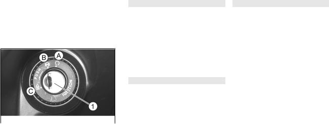
(02_07, 02_08) Key switch (02_07, 02_08)
«1» The ignition switch «1» is locatedon the right-hand side, near the
headstock.
|
|
«2» |
NOTE |
|
|
|
|
|
|
|
|
||
|
|
|
KEY«2» |
ACTIVATES |
THE IGNITION |
|
|
|
|
SWITCH/ STEERING LOCK, THE SADDLE |
|||
|
|
2 1 |
LOCK AND THE GLOVE-BOX LATCH. TWO |
|||
02_07 |
|
|
KEYS ARE |
SUPPLIED |
WITH THE VEHICLE |
|
|
|
|
(ONE IS A SPARE KEY). |
|||
|
|
|
|
|||
|
|
|
|
|
|
|
|
|
|
NOTE |
|
|
|
|
|
KEEP THE SPARE KEY IN DIFFERENT |
||||
|
|
|
||||
|
|
|
|
PLACE, NOT WITH THE VEHICLE. |
||
Vehicle 2 / 2
23
2 / 2 Vehicle
02_08
ON «A»
OFF «B»
LOCK «C»
SWITCH POSITIONS
ON «A»: The engine and lights can be set to work. The key cannot be ex tracted.
OFF «B»: The engine and lights can not be set to work. The key may be removed.
LOCK «C»: The steering is locked. It is not possible to start the engine or switch on the lights. The key can be extracted.
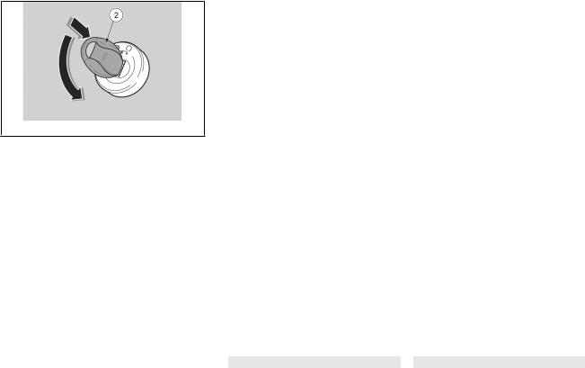
|
Locking the steering wheel |
«LOCK»
CAUTION
AVOIDING LOSING CONTROL OF THE VE HICLE - NEVER TURN THE KEY TO «LOCK» WHILE RIDING.
24
∙«2» «OFF»
∙«2» «2» « LOCK»
To lock the steering:
∙Turn the handlebar fully leftwards.
∙Turn and set the key «2» to «OFF»
NOTE
TURN THE KEY AND MOVE THE HANDLEBAR AT THE SAME TIME.
∙Press and turn the key «2» anticlockwise (to the left), move the handlebar slowly until the key «2» is set to «LOCK».
∙Extract the key.
|
|
|
Switch direction indicators |
||
|
|||||
|
(02_09) |
|
(02_09) |
||
|
|
«3» |
Move the switch «3» to the left, to |
||
|
|
|
indicate a left turn; move the |
||
|
|
« 3» |
switch «3» to the right, to indicate |
||
|
|
|
a right turn. Press the central part |
||
|
|
3 |
of the switch 3 to deactivate the |
||
|
|
|
|
turn indicator. |
|
|
|
|
|
||
|
|
|
|
|
|
|
|
"ON" |
|
NOTE |
|
02_09 |
|
|
|
||
|
|
ELECTRICAL COMPONENTS FUNCTION ONLY |
|||
|
|
||||
WHEN THE IGNITION KEY IS SET TO "ON"
Vehicle 2 / 2
25
2 / 2 Vehicle
(02_10) |
Horn button (02_10) |
||
«2» To action the horn, |
press button |
||
|
|
«2». |
|
|
|
|
|
|
|
|
|
"ON" |
NOTE |
|
|
|
|
||
|
ELECTRICAL COMPONENTS |
FUNCTION ONLY |
|
|
|
WHEN THE IGNITION KEY IS SET TO "ON" |
|
02_10
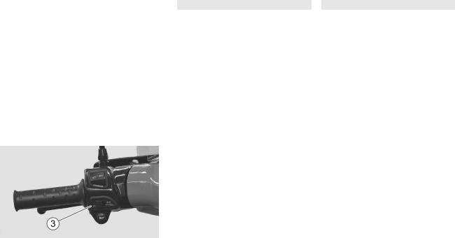
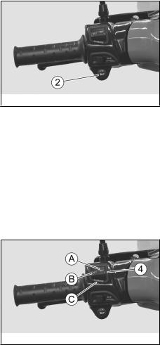
(02_11) |
Light switch (02_11) |
|
«4» «A» |
If the light switch «4» is set to |
|
|
«A», the high-beam light is activa |
|
« B» |
ted; if it is set to «B», the low- |
|
|
beam light is activated. |
|
|
|
|
|
|
NOTE |
"ON" |
ELECTRICAL COMPONENTS FUNCTION ONLY |
|
|
WHEN THE IGNITION KEY IS SET TO "ON" |
|
«C» |
PASSING button «C» |
|
|
Press the PASSING button and the |
|
|
high-beam light is flashed. |
|
|
|
|
|
|
NOTE |
«C» |
RELEASING THE BUTTON «C» DEACTIVATES |
|
|
THE HIGH-BEAM FLASH. |
|
02_11
26
|
|
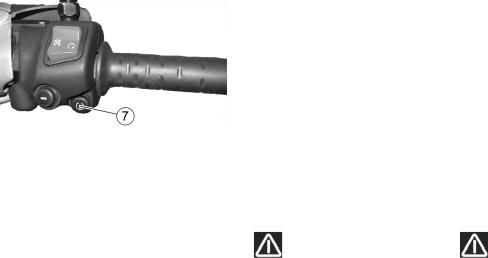
(02_12) |
Start-up button (02_12) |
|
|
||||
|
|
"7" |
By pressing the starter button "7", |
|
|
|
|
the starter motor makes the engine |
|
|
|
|
rotate. |
|
|
|
|
|
|
|
|
|
|
NOTE |
|
|
"ON" |
ELECTRICAL COMPONENTS FUNCTION ONLY |
|
|
|
|
WHEN THE IGNITION KEY IS SET TO "ON" |
|
02_12 |
|
|
|
|
(02_13) |
Engine stop button (02_13) |
|
|
|
|
|
|
CAUTION |
|
DO NOT ACTION THE ENGINE STOP SWITCH |
|
«6» |
«6» WHILE RIDING THE VEHICLE. |
|
|
|
|
|
|
NOTE |
"ON" |
ELECTRICAL COMPONENTS FUNCTION ONLY |
|
|
WHEN THE IGNITION KEY IS SET TO "ON" |
|
Vehicle 2 / 2
27
2 / 2 Vehicle
02_13
02_14
«6» |
The engine stop switch «6» functions |
|
|
as a safety and emergency switch. |
|
«6» «ON» |
When the switch «6» set to «ON» the |
|
«OFF» |
engine can be started; when it is set |
|
|
to «OFF», the engine stops. |
|
|
|
|
|
|
CAUTION |
|
WITH THE ENGINE OFF AND THE IGNITION |
|
«ON» |
SWITCH SET TO «ON» THE BATTERY MAY |
|
|
GET DISCHARGED. WITH THE ENGINE OFF |
|
|
AND AFTER IT STOPS TURN THE IGNITION |
|
«OFF» |
SWITCH TO «OFF». |
|
|
|
|
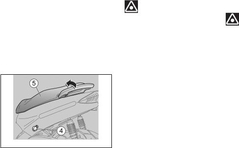
(02_14) |
Power supply socket (02_14) |
∙ |
∙ There is a 12V plug socket |
12V «4» |
«4» inside the helmet com |
|
partment. |
28
∙ 180W |
|
∙ This socket can be used to |
|
|
|
power equipment with a max |
|
|
|
imum power of 180 W (mobile |
|
|
|
telephones, hand lamp, |
|
|
|||
|
etc.). |
||
|
|
||
|
|
||
|
|
CAUTION |
|
USING THIS SOCKET FOR A LONG PERIOD CAN RESULT IN A FULLY DISCHARGED BATTERY.
02_15
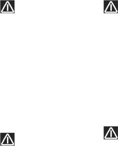
(02_15) |
Opening the saddle (02_15) |
|
|
To unlock the saddle: |
|
∙ |
|
∙ Rest the vehicle on its |
|
|
centre stand. |
∙ |
|
∙ Insert the key in the saddle |
|
|
opening lock. |
∙ |
«4» |
∙ Turn the key «4» anticlock |
|
|
wise. |
Vehicle 2 / 2
29
2 / 2 Vehicle
∙ |
«5» |
∙ Lift the saddle «5». |
||
∙ |
|
∙ To lock the saddle, lower |
||
|
|
and press it (without forc |
||
|
|
ing it) to trip the lock. |
||
|
|
|
|
|
|
|
|
CAUTION |
|
|
BEFORE RIDING, MAKE SURE THAT THE |
|||
|
SADDLE IS CORRECTLY LOCKED INTO PO |
|||
|
|
|
SITION. |
|
(02_16, 02_17) |
Identification (02_16, 02_17) |
|||
|
Write down the chassis and engine |
|||
|
numbers in the specific space in |
|||
|
this manual. |
|||
|
The chassis number can be used to |
|||
|
order spare parts. |
|||
|
|
|
|
|
|
|
|
NOTE |
|
|
|
|
|
|
|
|
|
ALTERING IDENTIFICATION NUMBERS CAN |
|
|
BE SERIOUSLY PUNISHED BY LAW, PAR |
|||
|
TICULARLY |
MODIFYING THE CHASSIS |
||
|
NUMBER WILL |
IMMEDIATELY INVALIDATE |
||
|
THE WARRANTY. |
|||
30
 Loading...