


The illustrations show SC-PM33DB
Before connecting, operating or adjusting this product, please read the instructions completely.
Please keep this manual for future reference.
Note:
“EB” on the packaging indicates the United Kingdom.
Operations in these instructions are described using remote control, but you can do the operations with the main unit if the controls are the same.
Unless otherwise indicated,illustrations in the operating instructions are of SC-PM33DB.
Your unit may not look exactly as illustrated.
Table of contents |
|
Caution for AC Mains Lead................... |
3 |
Placement of speakers.......................... |
3 |
Getting started ....................................... |
4 |
Overview of controls ............................. |
7 |
Discs....................................................... |
9 |
Cassette tape ( PM33DB only) ................. |
11 |
Radio....................................................... |
12 |
DAB......................................................... |
13 |
Timer....................................................... |
17 |
Sound adjustment ................................. |
19 |
External unit........................................... |
20 |
Troubleshooting guide.......................... |
21 |
Specifications ........................................ |
22 |
Safety precautions ................................ |
23 |
Maintenance........................................... |
23 |
Operating Instructions
CD Stereo System
Model No. SC-PM33DB
SC-PM32DB
SUPPLIED ACCESSORIES
Please check and identify the supplied accessories.
Use numbers indicated in parentheses when asking for replacement parts. (As of February 2006).
1 x Remote control 1 x AC mains lead
|
PM33DB |
|
|
(K2CT3CA00004) |
(N2QAYB000003) |
|
|
||
|
|
|
|
|
|
PM32DB |
|
|
|
(N2QAYB000004) |
|
|
||
|
|
|
||
1 x FM indoor antenna |
|
1 x DAB “T” antenna |
||
|
|
|
|
|
(RSA0007-L) 

 (N1EADY000001)
1 x Antenna plug 1 x AM loop antenna adaptor
(K1YZ02000013)  (N1DAAAA00001)
2 x Remote control batteries
|
|
|
|
|
|
|
|
|
|
|
|
|
|
|
|
|
|
|
|
|
|
|
|
|
|
|
|
|
|
|
|
|
|
|
|
|
|
|
|
|
|
|
|
|
|
|
|
|
|
|
|
|
|
|
|
|
|
|
|
|
|
|
|
|
EB |
|
|
|
|
|
|
|
|
|
RQTV0123-B |
||

Dear customer
Thank you for purchasing this product.
For optimum performance and safety, please read these instructions carefully.
These operating instructions are applicable to the following system.
|
System |
SC-PM33DB |
SC-PM32DB |
||
|
|
|
|
|
|
|
Main unit |
SA-PM33DB |
SA-PM32DB |
||
|
|
|
|
|
|
|
Speakers |
SB-PM33DB |
SB-PM3 |
||
|
|
|
|
|
|
|
|
|
|
|
|
|
|
|
|
|
|
|
|
|
|
|
|
|
|
|
|
|
|
|
|
|
|
|
|
|
|
|
|
|
|
|
|
|
|
|
|
|
|
|
|
|
|
Side of product
Inside of product
This product may receive radio interference caused by mobile telephones during use. If such interference is apparent, please increase separation between the product and the mobile telephone.
The socket outlet shall be installed near the equipment and easily accessible or the mains plug or an appliance coupler shall remain readily operable.
THIS UNIT IS INTENDED FOR USE IN MODERATE CLIMATES.
RQTV0123
– If you see this symbol –
Information on Disposal for Users of Waste Electrical & Electronic Equipment (private households)
This symbol on the products and/or accompanying documents means that used electrical and electronic products should not be mixed with general household waste.
For proper treatment, recovery and recycling, please take these products to designated collection points, where they will be accepted on a free of charge basis. Alternatively, in some countries you may be able to return your products to your local retailer upon the purchase of an equivalent new product.
Disposing of this product correctly will help to save valuable resources and prevent any potential negative effects on human health and the environment which could otherwise arise from inappropriate waste handling. Please contact your local authority for further details of your nearest designated collection point.
Penalties may be applicable for incorrect disposal of this waste, in accordance with national legislation.
For business users in the European Union
If you wish to discard electrical and electronic equipment, please contact your dealer or supplier for further information.
Information on Disposal in other Countries outside the European Union
This symbol is only valid in the European Union.
If you wish to discard this product, please contact your local authorities or dealer and ask for the correct method of disposal.
■ Sales and Support Information
(For the United Kingdom and Republic of Ireland)
Customer Care Centre
•For UK customers: 08705 357357
•For Republic of Ireland customers: 01 289 8333
•Visit our website for product information
•E-mail: customer.care@panasonic.co.uk
Direct Sales at Panasonic UK
•Order accessory and consumable items for your product with ease and confi dence by phoning our Customer Care Centre Monday-Friday 9:00am-5:30pm. (Excluding public holidays)
•Or go on line through our Internet Accessory ordering application at www.panasonic.co.uk
•Most major credit and debit cards accepted.
•All enquiries transactions and distribution facilities are provided directly by Panasonic UK Ltd.
•It couldn’t be simpler!
•Also available through our Internet is direct shopping for a wide range of fi nished products, take a browse on our website for further details.
Interested in purchasing an extended guarantee? Please call 0870 240 6284 or visit our website www.panasonic.co.uk/guarantee.
2
Caution for AC Mains Lead
(For United Kingdom)
(“EB” area code model only)
For your safety, please read the following text carefully.
This appliance is supplied with a moulded three pin mains plug for your safety and convenience.
A 5-ampere fuse is fi tted in this plug.
Should the fuse need to be replaced please ensure that the replacement fuse has a rating of 5-ampere and that it is approved by ASTA or BSI to BS1362.
Check for the ASTA mark m or the BSI mark o on the body of the fuse.
If the plug contains a removable fuse cover you must ensure that it is refi tted when the fuse is replaced.
If you lose the fuse cover the plug must not be used until a replacement cover is obtained.
A replacement fuse cover can be purchased from your local dealer.
CAUTION!
IF THE FITTED MOULDED PLUG IS UNSUITABLE FOR THE SOCKET OUTLET IN YOUR HOME THEN THE FUSE SHOULD BE REMOVED AND THE PLUG CUT OFF AND DISPOSED OF SAFELY.
THERE IS A DANGER OF SEVERE ELECTRICAL SHOCK IF THE CUT OFF PLUG IS INSERTED INTO ANY 13-AMPERE SOCKET.
If a new plug is to be fi tted please observe the wiring code as stated below.
If in any doubt please consult a qualifi ed electrician.
IMPORTANT
The wires in this mains lead are coloured in accordance with the following code:
Blue: Neutral, Brown: Live.
As these colours may not correspond with the coloured markings identifying the terminals in your plug, proceed as follows:
The wire which is coloured Blue must be connected to the terminal which is marked with the letter N or coloured Black or Blue.
The wire which is coloured Brown must be connected to the terminal which is marked with the letter L or coloured Brown or Red.
WARNING: DO NOT CONNECT EITHER WIRE TO THE EARTH TERMINAL WHICH IS MARKED WITH THE LETTER E, BY THE EARTH SYMBOL nOR COLOURED
GREEN OR GREEN/YELLOW.
THIS PLUG IS NOT WATERPROOF—KEEP DRY.
Before use
Remove the connector cover.
How to replace the fuse
The location of the fuse differ according to the type of AC mains plug (figures A and B). Confirm the AC mains plug fitted and follow the instructions below.
Illustrations may differ from actual AC mains plug.
1. Open the fuse cover with a screwdriver.
Figure A |
Figure B |
Fuse cover
2. Replace the fuse and close or attach the fuse cover.
Figure A |
Figure B |
Fuse |
Fuse |
(5 ampere) |
|
(5 ampere) |
|
Placement of speakers
Speakers are designed identically so that no left or right channel orientation is necessary.
Use only the supplied speakers.
The combination of the main unit and speakers provide the best sound. Using other speakers can damage the unit and sound quality will be negatively affected.
Note
•Keep your speakers at least 10 mm away from the system for proper ventilation.
•These speakers do not have magnetic shielding. Do not place them near televisions, personal computers or other devices easily infl uenced by magnetism.
•You cannot take the front net off the speakers.
Caution
•Use the speakers only with the recommended system. Failure to do so can damage the amplifier and speakers, and can cause fire. Consult a qualified service person if damage occurs or if a sudden change in performance is apparent.
•Do not attach these speakers to walls or ceilings.
RQTV0123
3

Getting started
Step 1 - Making the connections
Connect the AC mains lead only after all other connections have been made.
1 Connect the AM loop antenna.
AM loop antenna
Stand the antenna up on its base. Keep the loose antenna cord away from other wires and cords.
2 Connect the FM indoor antenna.
Adhesive
 tape
tape
FM indoor
 antenna
Tape the antenna to a wall or column, in a position with least amount of interference.
RQTV0123
4

3 DAB “T” antenna
The cross bar of the T should be kept fi rmly stretched.
Find a position with good reception.
There is a function on the unit to check signal quality.
Be sure to fully tighten the screw.
Adhesive tape
For best reception
A DAB outdoor antenna is recommended (refer to page 6).
Even when the connector is perfectly inserted, depending on the type of inlet used, the front part of the connector may jut out as shown in the drawing. However there is no problem using the unit.
5 Connect the speaker cables.
Black (·)
Red (ª) Red (ª)
Black (·)
RQTV0123
Incorrect connection can damage the unit.
5

Getting started (continued)
Optional antenna connections
FM outdoor antenna |
AM outdoor antenna |
DAB outdoor antenna |
|
|||||||||||||||||||||
|
|
|
|
FM outdoor antenna |
|
|
|
|
|
|
|
AM outdoor antenna |
DAB outdoor antenna |
|
||||||||||
|
|
|
|
|
|
|
|
|
|
|
|
|
|
|
(not included) |
(not included) |
|
|||||||
|
|
|
|
(not included) |
|
|
|
|
|
|
|
|
|
|
|
|
|
|
|
|
|
|
||
|
|
|
|
|
|
|
|
|
|
|
|
|
|
|
|
|
|
|
|
|
|
|||
|
|
|
|
|
|
|
|
|
|
|
|
|
|
|
|
|
|
|
|
|
|
|
|
|
|
|
|
|
|
|
|
|
|
|
|
|
|
|
|
|
|
|
|
|
|
|
|
|
|
|
|
|
|
|
|
|
|
|
|
|
|
|
|
|
|
|
|
|
|
|
|
|
|
|
|
|
|
|
|
|
|
|
|
|
|
|
|
|
|
|
|
|
|
|
|
|
|
|
|
|
|
|
|
|
|
|
|
|
|
|
|
|
|
|
|
|
|
|
|
|
|
|
|
|
|
|
|
|
|
|
|
|
|
|
|
|
|
|
|
|
|
|
|
|
|
|
|
|
|
|
|
|
|
|
|
|
|
|
|
|
|
|
|
|
|
|
|
|
|
|
|
|
|
|
|
AM loop antenna |
|
75 Ω coaxial cable |
(included) |
|
Be sure to fully |
||
(not included) |
||
tighten the screw. |
||
|
•Never use an outdoor antenna during a lightning storm.
•You can connect the FM outdoor antenna for better reception. Please consult your dealer for installation.
•Disconnect the FM indoor antenna if an FM outdoor antenna is installed.
•Connect the AM outdoor antenna without removing the AM loop antenna. Run 5 to 12 m of vinyl-covered wire horizontally along a window or other convenient location.
Step 2 - Inserting batteries into the remote control
■ Batteries
• Insert so the poles (+ and –) match those in the remote control.
• Remove if the remote control is not going to be used for a long period of time. Store in a cool, dark place.
• Do not use rechargeable type batteries.
• Mishandling of batteries in the remote control can cause electrolyte leakage, which may cause a fi re.
Do not:
•mix old and new batteries;
•use different types of batteries at the same time;
•heat or expose to fl ame;
• take apart or short-circuit;
• attempt to recharge alkaline or manganese batteries;
• use batteries if their covering has been peeled off.
■Use
Aim at the remote control sensor, avoiding obstacles, at a maximum range of 7 m directly in front of the unit.
Refer to page 7 for remote control signal sensor position.
Step 3 - DEMO function
0- $"
0- $"
RQTV0123
When the unit is fi rst plugged in, a demonstration of its functions may be shown on the display.
If the demo setting is off, you can show a demonstration by selecting “DEMO ON”.
Press and hold [7, -DEMO].
The display changes each time the button is held down.
$%-/ /&& $%-/ /.
While in standby mode, select “DEMO OFF” to reduce power consumption.
6

Overview of controls
Main unit
Refer to the numbers in parentheses for page reference.
PM33DB
Top of unit
Headphone jack (PHONES)
Avoid listening for prolonged periods of time to prevent hearing damage.
Plug type: 3.5 mm stereo
(not included)
Cassette lid
Cassette lid open (11)
AC supply indicator (AC IN) |
|
|
This indicator lights when the unit |
Display panel |
|
is connected to the AC mains |
||
|
||
supply. |
5 Bass/Treble selection (19) |
|
1 Standby/on switch (y/l) |
Remote control sensor |
|
(9, 18) |
||
Recording start/pause (11, 20) |
||
Press to switch the unit from on |
||
to standby mode or vice versa. |
|
|
In standby mode, the unit is still |
6 Disc skip/search, tape |
|
consuming a small amount of |
||
power. |
fast-forward/rewind, tune/ |
|
Music port jack (20) |
preset channel selection, |
|
2 Disc play/pause (9, 10, 11) |
time adjustment, bass/treble |
|
adjustment (9, 10, 11, 12, 14, |
||
|
15, 17, 18, 19) |
|
Stop/Demo (6, 9, 10, 11) |
7 Volume control |
|
8 Tape play (11) |
||
|
||
3Tuner/Band/DAB selection |
Disc tray open/close (9, 11) |
|
(12, 14) |
|
|
|
Disc tray |
|
4 Music port selection (20) |
|
|
PM32DB |
|
|
1 Standby/on switch (y/l) |
5 Bass/Treble selection (19) |
|
|
||
(9, 18) |
|
Press to switch the unit from on |
6 Disc skip/search, tune/ |
|
to standby mode or vice versa. |
||
preset channel selection, |
||
In standby mode, the unit is still |
||
time adjustment, bass/treble |
||
consuming a small amount of |
||
power. |
adjustment (9, 10, 12, 14, 15, |
|
Music port jack (20) |
17, 18, 19) |
|
2 Disc play/pause |
7 Volume control |
|
|
||
(9, 10) |
|
|
4 Music port selection (20) |
3 Tuner/Band/DAB selection |
|
|
(12, 14) |
|
Stop/Demo (6, 9, 10) |
|
RQTV0123
7
RQTV0123
8
Overview of controls (continued)
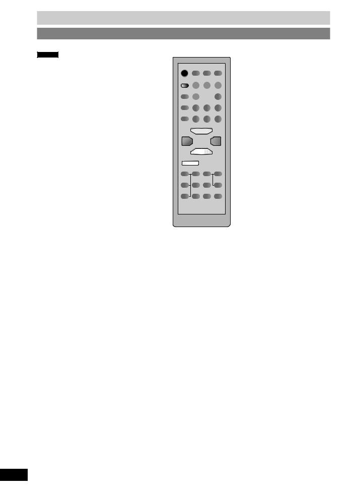
Remote control
Buttons such as 1 function the same as the controls on the main unit.
PM33DB
1
Sleep timer/ -Auto off (17)
Program (10, 12, 14)
Play mode (9, 11, 12, 14, 15)
Repeat (10)
Display (9, 15)
Clear, Stop (9, 10, 11)
CLEAR
3
8
7
Album, DAB menu selection (9, 10, 15, 16)
Enter (10, 15, 16)
Surround (19)
DAB menu (15, 16)
DAB secondary (15)
PM32DB
1
Sleep timer/ -Auto off (17)
Program (10, 12, 14)
Play mode (9, 12, 14, 15)
Repeat (10)
Display (9, 15)
 CLEAR
CLEAR
4
3
7
Album, DAB menu selection (9, 10, 15, 16)
Enter (10, 15, 16)
Surround (19)
DAB menu (15, 16)
DAB secondary (15)
Clock/Timer (17, 18)
Play timer/Record timer (18)
Numeric (9, 10, 12, 14, 15)
Delete (10)
2
4
6
5
Preset EQ (19)
Muting
Dimmer
Clock/Timer (17, 18)
Play timer (18)
Numeric (9, 10, 12, 14, 15)
Delete (10)
2
Clear, Stop (9, 10)
6
5
Preset EQ (19)
Muting
Dimmer
This function allows you to |
Dims the display panel. |
Long press of [DISPLAY] key |
|
turn off the unit in disc or tape |
|
will switch to fast text scrolling. |
|
mode only after left unused for |
|
This function allows you to |
|
10 minutes. |
|
||
|
scroll the display setting faster |
||
|
Mutes the sound. |
||
The setting is maintained even |
than current setting. |
||
|
|||
|
|
||
if the unit is turned off. |
|
|
|
• Press and hold untill the “AUTO OFF” |
• Press the button to activate. |
• Long press again to turn OFF fast text |
|
indicated. |
• Press again to cancel. |
scrolling. |
|
• Press and hold again to cancel. |
|
|
 Loading...