Motorola MC10H605FN, MC10H605FNR2, MC100H605FN, MC100H605FNR2 Datasheet

MOTOROLA
SEMICONDUCTOR TECHNICAL DATA
Registered Hex ECL/TTL
Translator
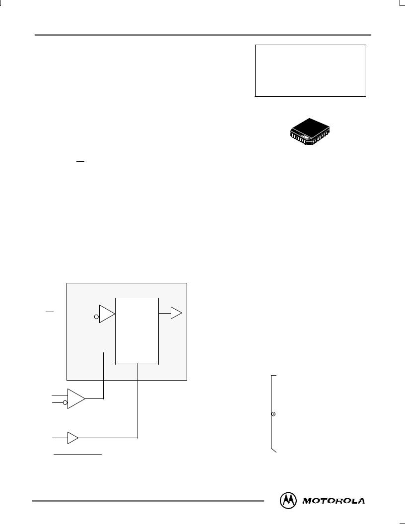
The MC10/100H605 is a 6±bit, registered, dual supply ECL to TTL translator. The device features differential ECL inputs for both data and clock. The TTL outputs feature balanced 24mA sink/source capabilities for driving transmission lines.
With its differential ECL inputs and TTL outputs the H605 device is ideally suited for the receive function of a HPPI bus type board±to±board interface application. The on chip registers simplify the task of synchronizing the data between the two boards.
A VBB reference voltage is supplied for use with single±ended data or clock. For single±ended applications the VBB output should be connected to the ªbarº inputs (Dnor CLK) and bypassed to ground via a 0.01μF capacitor. To minimize the skew of the device differential clocks should be used.
The ECL level Master Reset pin is asynchronous and common to all flip±flops. A ªHIGHº on the Master Reset forces the Q outputs ªLOWº.
The device is available in either ECL standard: the 10H device is compatible with MECL 10H logic levels while the 100H device is compatible with 100K logic levels.
•Differential ECL Data and Clock Inputs
•24mA Sink, 24mA Source TTL Outputs
•Dual Power Supply
•Multiple Power and Ground Pins to Minimize Noise
•2.0ns Part±to±Part Skew
|
|
|
|
LOGIC SYMBOL |
|
|
|
||||
|
|
|
|
1 OF 6 BITS |
|
|
|
|
|
||
Dn |
|
|
|
|
|
|
|
|
|
|
Qn |
|
|
|
|
D |
|
Q |
|
|
|||
|
|
|
|
|
|
||||||
Dn |
|
|
|
|
|
|
|||||
|
|
|
|
|
|
|
|
|
|
||
 CLK
CLK
R
CLK
CLK
MR
VBB 
MECL 10H is a trademark of Motorola, Inc.
MC10H605
MC100H605
|
|
|
|
|
|
|
|
FN SUFFIX |
|
||
|
|
|
|
|
|
PLASTIC PACKAGE |
|
||||
|
|
|
|
|
|
|
|
CASE 776±02 |
|
||
|
|
|
|
|
|
||||||
PIN NAMES |
|
|
|
|
|||||||
|
|
|
|
|
|
|
|
|
|
|
|
|
|
PIN |
|
|
|
|
FUNCTION |
|
|||
|
|
|
|
|
|
|
|
|
|
|
|
|
D0±D5 |
|
|
|
True ECL Data Inputs |
||||||
|
|
|
|
|
|
|
|
Inverted ECL Data Inputs |
|||
|
D0±D5 |
|
|
|
|||||||
|
|
|
|
|
|
Differential ECL Clock Input |
|||||
|
CLK, CLK |
|
|||||||||
|
MR |
|
|
|
ECL Master Reset Input |
||||||
|
Q0±Q5 |
|
|
|
TTL Outputs |
|
|||||
|
VCCE |
|
|
|
ECL VCC |
|
|||||
|
VCCT |
|
|
|
TTL VCC |
|
|||||
|
GND |
|
|
|
TTL Ground |
|
|||||
|
VEE |
|
|
|
ECL VEE |
|
|||||
TRUTH TABLE |
|
||||||||||
|
|
|
|
|
|
|
|
||||
|
Dn |
|
MR |
|
TCLK/CLK |
|
Qn+1 |
||||
|
|
|
|
|
|
|
|
|
|||
|
L |
|
|
L |
|
Z |
|
L |
|||
|
H |
|
|
L |
|
Z |
|
H |
|||
|
X |
|
|
H |
|
X |
|
L |
|||
|
|
|
|
|
|
|
|
|
|
|
|
Z = LOW to HIGH Transition
Pinout: 28±Lead PLCC (Top View)
|
|
|
|
|
|
Q3 VCCT Q4 GND |
Q5 VCCT MR |
|
|
|
|
|||||||||||||
|
|
|
|
|
|
|
|
|
|
|
|
|
|
|
|
|
|
|
|
|
|
|
|
|
|
|
|
|
|
|
25 |
24 |
23 |
|
22 |
|
21 |
20 |
|
19 |
|
|
|
|
|
||||
|
Q2 |
|
|
|
|
|
|
|
|
|
|
|
|
|
|
|
|
18 |
|
|
D5 |
|||
|
26 |
|
|
|
|
|
|
|
|
|
|
|
|
|
|
|||||||||
|
Q1 |
|
|
|
|
|
|
|
|
|
|
|
|
|
|
|
17 |
|
|
D5 |
||||
|
27 |
|
|
|
|
|
|
|
|
|
|
|
|
|
|
|
||||||||
|
Q0 |
|
|
|
|
|
|
|
|
|
|
|
|
|
|
|
|
|
|
|
|
|||
|
|
|
|
|
|
|
|
|
|
|
|
|
|
|
|
|
16 |
|
|
D4 |
||||
28 |
|
|
|
|
|
|
|
|
|
|
|
|
|
|
|
|||||||||
GND |
|
|
|
|
|
|
|
|
|
|
|
|
|
|
|
|
15 |
|
|
D4 |
||||
|
|
|
|
|
|
|
|
|
|
|
|
|
|
|
|
|
||||||||
|
CLK |
|
2 |
|
|
|
|
|
|
|
|
|
|
|
|
|
14 |
|
|
VCCE |
||||
|
|
|
|
|
|
|
|
|
|
|
|
|
|
|
|
|
||||||||
|
|
|
|
|
|
|
|
|
|
|
|
|
|
|
|
|
|
|
||||||
|
|
|
|
|
|
|
|
|
|
|
|
|
|
|
|
|
|
|
|
|
|
|
|
|
|
CLK |
|
|
|
|
|
|
|
|
|
|
|
|
|
|
|
|
13 |
|
|
D3 |
|||
|
|
3 |
|
|
|
|
|
|
|
|
|
|
|
|
|
|
||||||||
VBB |
|
|
|
|
|
|
|
|
|
|
|
|
|
|
|
12 |
|
|
D3 |
|||||
|
4 |
|
|
|
|
|
|
|
|
|
|
|
|
|
|
|||||||||
|
|
|
5 |
6 |
7 |
|
8 |
|
9 |
10 |
|
11 |
|
|
|
|
|
|||||||
|
|
|
|
|
|
|
|
|
|
|
|
|
|
|
|
|
|
|
|
|
|
|
|
|
|
|
|
|
|
|
|
|
|
|
|
|
|
|
|
|
|
|
|
|
|||||
|
|
|
|
|
|
|
D0 |
D0 |
VEE |
D1 |
D1 |
D2 |
D2 |
|
|
|
|
|||||||
9/96
Motorola, Inc. 1996 |
2±306 |
REV 3 |

MC10H605 MC100H605
10H ECL DC CHARACTERISTICS (VCCT = +5.0V ±5%; VEE = ±5.20V ±5%)
|
|
|
|
0°C |
|
|
25°C |
|
|
85°C |
|
|
|
|
|
|
|
|
|
|
|
|
|
|
|
|
|
Symbol |
Characteristic |
Min |
Typ |
Max |
Min |
Typ |
Max |
Min |
Typ |
Max |
Unit |
Condition |
|
|
|
|
|
|
|
|
|
|
|
|
|
|
|
IEE |
Supply Current |
|
|
63 |
75 |
|
63 |
75 |
|
61 |
75 |
mA |
|
IIH |
Input HIgh Current |
|
|
|
225 |
|
|
145 |
|
|
145 |
μA |
|
IIL |
Input Low Current |
|
0.5 |
|
|
0.5 |
|
|
0.5 |
|
|
μA |
|
VIH |
Input High Voltage |
|
±1170 |
|
±840 |
±1130 |
|
±810 |
±1060 |
|
±720 |
mV |
|
VIL |
Input Low Voltage |
|
±1950 |
|
±1480 |
±1950 |
|
±1480 |
±1950 |
|
±1480 |
mV |
|
VBB |
Output Bias Voltage |
±1400 |
|
±1280 |
±1370 |
|
±1270 |
±1330 |
|
±1210 |
mV |
|
|
VDiff |
Input Differential Voltage |
150 |
|
|
150 |
|
|
150 |
|
|
mV |
|
|
Vmax |
Input Common |
Mode |
|
|
0 |
|
|
0 |
|
|
0 |
mV |
|
CMRR |
Reject Range |
|
|
|
|
|
|
|
|
|
|
|
|
|
|
|
|
|
|
|
|
|
|
|
|
|
|
Vmin |
Input Common |
Mode |
±2800 |
|
|
±2800 |
|
|
±2800 |
|
|
mV |
VEE = ±4.94 |
CMRR |
Reject Range |
|
±3000 |
|
|
±3000 |
|
|
±3000 |
|
|
|
VEE = ±5.20 |
|
|
|
±3300 |
|
|
±3300 |
|
|
±3300 |
|
|
|
VEE = ±5.46 |
100H ECL DC CHARACTERISTICS (VCCT = +5.0V ±5%; VEE = ±4.5V ±0.3V)
|
|
|
|
0°C |
|
|
25°C |
|
|
85°C |
|
|
|
|
|
|
|
|
|
|
|
|
|
|
|
|
|
Symbol |
Characteristic |
Min |
Typ |
Max |
Min |
Typ |
Max |
Min |
Typ |
Max |
Unit |
Condition |
|
|
|
|
|
|
|
|
|
|
|
|
|
|
|
IEE |
Supply Current |
|
|
65 |
75 |
|
65 |
75 |
|
70 |
85 |
mA |
|
IIH |
Input HIgh Current |
|
|
|
225 |
|
|
145 |
|
|
145 |
μA |
|
IIL |
Input Low Current |
|
0.5 |
|
|
0.5 |
|
|
0.5 |
|
|
μA |
|
VIH |
Input High Voltage |
|
±1165 |
|
±880 |
±1165 |
|
±880 |
±1165 |
|
±880 |
mV |
|
VIL |
Input Low Voltage |
|
±1810 |
|
±1475 |
±1810 |
|
±1475 |
±1810 |
|
±1475 |
mV |
|
VBB |
Output Bias Voltage |
±1400 |
|
±1280 |
±1400 |
|
±1280 |
±1400 |
|
±1200 |
mV |
|
|
VDiff |
Input Differential Voltage |
150 |
|
|
150 |
|
|
150 |
|
|
mV |
|
|
Vmax |
Input Common |
Mode |
|
|
0 |
|
|
0 |
|
|
0 |
mV |
|
CMRR |
Reject Range |
|
|
|
|
|
|
|
|
|
|
|
|
|
|
|
|
|
|
|
|
|
|
|
|
|
|
Vmin |
Input Common |
Mode |
±2000 |
|
|
±2000 |
|
|
±2000 |
|
|
mV |
VEE = ±4.20 |
CMRR |
Reject Range |
|
±2200 |
|
|
±2200 |
|
|
±2200 |
|
|
|
VEE = ±4.50 |
|
|
|
±2400 |
|
|
±2400 |
|
|
±2400 |
|
|
|
VEE = ±4.80 |
* NOTE: DO NOT short the ECL inputs to the TTL VCC.
MECL Data |
2±307 |
MOTOROLA |
DL122 Ð Rev 6 |
|
|
 Loading...